0mm(135mm,-18mm)![[Uncaptioned image]](/html/1305.5766/assets/x1.png)
CLIC Linear Collider Studies
Input to the Snowmass process 2013
May 24, 2013
This paper addresses the issues in question for Energy Frontier Lepton and Gamma Colliders by the Frontier Capabilities group of the Snowmass 2013 process and is structured accordingly. It will be accompanied by a paper describing the Detector and Physics studies for the CLIC project [c:snowmasspd] currently in preparation for submission to the Energy Frontier group.
Corresponding editors: Dominik Dannheim, Philippe Lebrun, Lucie Linssen,
Daniel Schulte, Steinar Stapnes.
1 Introduction
The Compact Linear Collider (CLIC) is a TeV scale high-luminosity linear collider under development. It is based on a novel two-beam acceleration technique providing acceleration gradients at the level of 100 MV/m. Recent implementation studies for CLIC have converged towards a staged approach offering a unique physics programme spanning several decades. In this scheme CLIC would provide high-luminosity collisions from a few hundred GeV to 3 TeV. The first stage, at or above the 350 GeV top pair production threshold, gives access to precision Higgs physics through the Higgsstrahlung and WW fusion production processes, providing absolute values of Higgs couplings to both fermions and bosons. This stage also addresses precision top physics. The second stage, around 1.5 TeV, opens the energy frontier, allowing for the discovery of new physics phenomena. This stage also gives access to additional Higgs properties, such as the top-Yukawa coupling, the Higgs potential and rare Higgs decay branching ratios. The ultimate CLIC energy of 3 TeV enlarges the CLIC physics potential even further covering the complete scope for precision Standard Model physics, direct searches for pair-production of new particles with masses up to 1.5 TeV and optimal sensitivity to new physics and much higher masses through precision measurements. A staged implementation of CLIC along the lines described would open the door to an impressive long-term and timely physics programme at the energy frontier, beyond the LHC programme. This machine is therefore considered an important option for a post-LHC facility at CERN.
The feasibility studies for the CLIC accelerator have over the last years systematically and successfully addressed the main technical challenges of the accelerator project. Similarly, detailed detector and physics studies confirm the ability to perform high-precision measurements at CLIC.
For more detailed descriptions we refer to the following documents:
-
•
CLIC Linear Collider Studies, eds. D. Dannheim et al., submitted to the update process of the European Strategy for Particle Physics, July 2012 [CLIC_Strategy_Input];
-
•
The Physics Case for an Linear Collider, eds. J. Brau et al., submitted to the update process of the European Strategy for Particle Physics, July 2012 [LC_Phys_Case_Strategy_Input];
-
•
A Multi-TeV Linear Collider based on CLIC Technology, CLIC Conceptual Design Report, 2012, eds. M. Aicheler et al. [CLICCDR_vol1];
-
•
Physics and Detectors at CLIC, CLIC Conceptual Design Report, eds. L. Linssen et al. [CLICCDR_vol2];
-
•
The CLIC Programme: towards a staged Linear Collider exploring the Terascale, CLIC Conceptual Design Report, 2012, eds. P. Lebrun et al. [CLICCDR_vol3].
The above CLIC CDR reports are supported by more than 1300 signatories111https://edms.cern.ch/document/1183227/ from the world-wide particle physics community.
2 CLIC parameters and layout for a 3-stage implementation
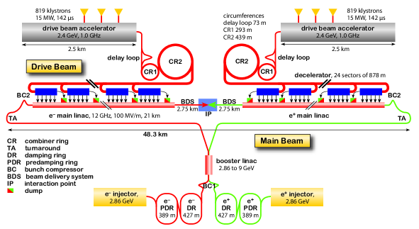
The CLIC layout at 3 TeV is shown in Figure 1, and the key parameters are given in Tables 1 and 2. The conceptual design is detailed in [CLICCDR_vol1] and [CLICCDR_vol3]. The CLIC accelerator can be built in energy stages, re-using the existing equipment for each new stage. At each energy stage the centre-of-mass energy can be tuned to lower values within a range of a factor three and with limited loss on luminosity performance. Two example scenarios of energy staging are given in [CLICCDR_vol3] with stages of , and , see Table 1 for scenario A and Table 2 for scenario B. In both scenarios the first and second stage use only a single drive-beam generation complex to feed both linacs, while in stage 3 each linac is fed by a separate complex.
| Parameter | Symbol | Unit | Stage 1 | Stage 2 | Stage 3 |
| Centre-of-mass energy | GeV | 500 | 1400 | 3000 | |
| Repetition frequency | Hz | 50 | 50 | 50 | |
| Number of bunches per train | 354 | 312 | 312 | ||
| Bunch separation | ns | 0.5 | 0.5 | 0.5 | |
| Accelerating gradient | MV/m | 80 | 80/100 | 100 | |
| Total luminosity | 2.3 | 3.2 | 5.9 | ||
| Luminosity above 99% of | 1.4 | 1.3 | 2 | ||
| Main tunnel length | km | 13.2 | 27.2 | 48.3 | |
| Charge per bunch | 6.8 | 3.7 | 3.7 | ||
| Bunch length | 72 | 44 | 44 | ||
| IP beam size | nm | 200/2.6 | 60/1.5 | 40/1 | |
| Normalized emittance (end of linac) | nm | 2350/20 | 660/20 | 660/20 | |
| Normalized emittance (IP) | nm | 2400/25 | — | — | |
| Estimated power consumption | MW | 272 | 364 | 589 |
| Parameter | Symbol | Unit | Stage 1 | Stage 2 | Stage 3 |
| Centre-of-mass energy | GeV | 500 | 1500 | 3000 | |
| Repetition frequency | Hz | 50 | 50 | 50 | |
| Number of bunches per train | 312 | 312 | 312 | ||
| Bunch separation | ns | 0.5 | 0.5 | 0.5 | |
| Accelerating gradient | MV/m | 100 | 100 | 100 | |
| Total luminosity | 1.3 | 3.7 | 5.9 | ||
| Luminosity above 99% of | 0.7 | 1.4 | 2 | ||
| Main tunnel length | km | 11.4 | 27.2 | 48.3 | |
| Charge per bunch | 3.7 | 3.7 | 3.7 | ||
| Bunch length | 44 | 44 | 44 | ||
| IP beam size | nm | 100/2.6 | 60/1.5 | 40/1 | |
| Normalized emittance (end of linac) | nm | — | 660/20 | 660/20 | |
| Normalized emittance | nm | 660/25 | — | — | |
| Estimated power consumption | MW | 235 | 364 | 589 |
Staging scenario A aims at achieving high luminosity at 500 GeV collision energy with increased beam current. This requires larger apertures in the accelerating structures which therefore operate at a lower gradient. The re-use of these structures in the second stage limits the achievable collision energy to 1.4 TeV. Staging scenario B aims at reducing the cost of the 500 GeV stage using full-gradient accelerating structures at nominal beam current, resulting in lower instantaneous luminosity. The re-use of these structures allows reaching 1.5 TeV collision energy in the second stage.
The recent LHC Higgs discovery makes an initial energy stage at 375 GeV instead of 500 GeV attractive, but final choices depend on future LHC findings. While the CDR design has been optimized for the 3 TeV stage only, the accelerator design is now being re-optimized also at the initial stages and using the improved understanding of the cost and power consumption obtained during the preparation of the CDR. In case of growing interest in a lower energy Higgs factory, studies of a klystron-based initial stage with a faster implementation could become part of this evaluation.
3 Main technical challenges and demonstrators
The CLIC design is based on three key technologies, which have been addressed experimentally:
-
•
The use of normal-conducting accelerating structures in the main linac with a gradient of , in order to limit the length of the machine. The RF frequency of and detailed parameters of the structure have been derived from an overall cost optimisation at 3 TeV. Experiments at KEK, SLAC and CERN verified the structure design and established its gradient and breakdown-rate performance.
-
•
The use of drive beams that run parallel to the colliding beams through a sequence of power extraction and transfer structures, where they produce the short, high-power RF pulses that are transferred into the accelerating structures. These drive beams are generated in a central complex. The drive-beam generation and use has been demonstrated in a dedicated test facility (CTF3) that has been constructed and operated for many years at CERN by the CLIC/CTF3 collaboration.
-
•
The high luminosity that is achieved by the very small beam emittances, which are generated in the damping rings and maintained during the transport to the collision point. These emittances are ensured by appropriate design of the beam lines and tuning techniques, as well as by a precision pre-alignment system and an active stabilisation system that decouples the magnets from the ground motion. Prototypes of both systems have demonstrated performance close to or better than the specifications.
Related system parameters have been benchmarked in CTF3, in advanced light sources, in the ATF(2) and CesrTA, and in other setups. In addition, a broad technical development programme has successfully addressed many critical components. Among them are those of the main linac, which are most important for the cost, and their integration into modules. The drive-beam components have largely been addressed in CTF3. Other performance-critical components have been developed and tested, e.g., the final focus magnets, which will be located in the detector and need to provide a very high field, and high-field damping ring wigglers, which rapidly reduce the beam emittances. Design studies foresee 80% polarisation of the electrons at collision, and the layout is compatible with addition of a polarized positron source. The successful validation of the key technologies and of the critical components establish confidence that the CLIC performance goals can be met.
4 Machine footprint, power and cost
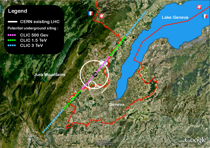
Detailed site studies show that CLIC can be implemented underground near CERN, with the central main and drive beam complex on the CERN domain, as shown in Figure 2. The site specifications do not constrain the implementation to this location.
The current CLIC parameters are the result of a global cost optimisation at , see Chapter 2.1 in [CLICCDR_vol1]. However, the technology can be used effectively over a wide range of centre-of-mass energies as explained above, and the design re-optimized for different objectives if desired.
The nominal electrical power consumption of all accelerator systems and services, including the experimental area and the detectors and taking into account network losses for transformation and distribution on site, is given in Table 3 for staging scenarios A and B. The table also shows residual power consumption without beams for two modes corresponding to short ("waiting for beam") and long ("shutdown") beam interruptions. The large variations and volatility of power consumption will allow CLIC to be operated as a peak-shaving facility, matching the daily and seasonal fluctuations in power demand on the network. Several paths aiming at reducing power consumption or improving the energy footprint of the machine have been identified and are under investigation, e.g., reduction of design current density in magnet windings and cables, replacement of normal-conducting by permanent or super-ferric magnets, development of high-efficiency klystrons and modulators, recovery and valorisation of waste heat. Furthermore, the on-going work to optimize the energy stages of CLIC will include power reduction as a key parameter.
| Staging scenario | [TeV] | |||
|---|---|---|---|---|
| 0.5 | 272 | 168 | 37 | |
| A | 1.4 | 364 | 190 | 42 |
| 3.0 | 589 | 268 | 58 | |
| 0.5 | 235 | 167 | 35 | |
| B | 1.5 | 364 | 190 | 42 |
| 3.0 | 589 | 268 | 58 |
| Staging scenario | Value [MCHF] | Labour [FTE years] |
|---|---|---|
| A | 15700 | |
| B | 14100 |
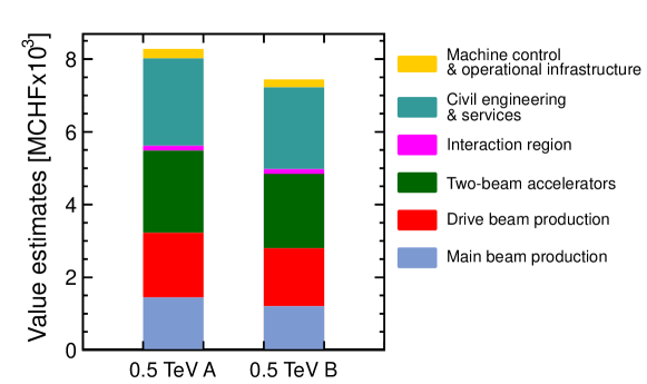
The cost estimates follow the “value” and “explicit labour” methodology used for the ILC Reference Design report [ILC_RDR_vol3]. They are based on the work breakdown structures established for the different stages of the two scenarios, and on unit costs obtained for other similar supplies or scaled from them, and from specific industrial studies. Uncertainties include technical and procurement risks, the latter being estimated from a statistical analysis of procurement for the LHC. The value estimates are expressed in Swiss francs (CHF) of December 2010 and can thus be escalated using relevant Swiss official indices. Explicit labour is estimated globally by scaling from LHC experience. The results are given in Table 4. The cost structure of the accelerators at 500 GeV collision energy for staging scenarios A and B is illustrated in Figure 3. The incremental value from the first to the second stage is about 4 MCHF/GeV (scenario B). Potential savings have been identified for a number of components and technical systems, amounting to about 10% of the total value. Examples of such savings are the substitution of the hexapods for the stabilisation of the main-beam quadrupoles with beam steering, the doubling in length of the support girders for the two-beam accelerator modules, or the alternative of using assembled quadrants instead of stacked disks for construction of the accelerating structures. Moreover, significant additional savings are expected from re-optimizing the design of the chosen energy stages.
5 Preparation timeline, project development and construction schedules
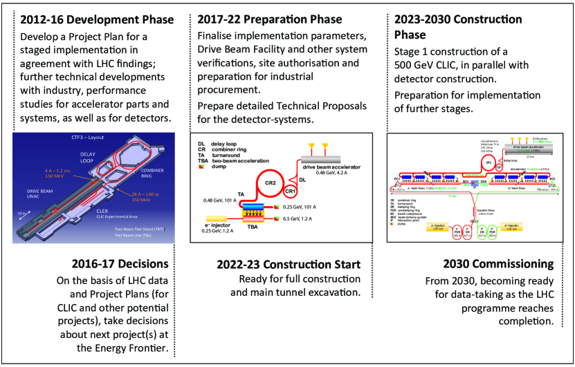
A development programme for the CLIC project has been established and is being carried out concurrently with LHC operation at 8 TeV and later full energy, covering the period until 2016-17. By that time both the LHC physics results and technical developments should have reached a maturity that would allow a decision about the most appropriate next project at the energy frontier beyond LHC. The major contenders are a Linear Collider with multi-TeV capabilities or an energy-upgraded LHC.
The CLIC development programme will lay the ground work for a complete Project Implementation Plan for the project, planned to be available by 2016-17. One important element is that a re-baselining of the CLIC energy stages is underway as explained above. Cost and power studies will follow; in addition to being key elements for the stage and design optimization additional technical developments can lead to important reductions. Important technical studies will address stability and alignment, timing and phasing, stray fields, and dynamic vacuum including collective effects. Other studies will address failure modes and operation issues. The collaboration will continue to identify and carry out system tests, and priorities are the measurements in CTF3, ATF, and related to the CLIC injector. Further X-band structure development and tests are high priorities as well as constructing integrated modules where a number of central functional elements are included and need to be optimized. Initial site studies have already been carried out and preliminary footprints have been identified for an initial machine as well as an ultimate 3 TeV layout, and these studies will continue. The 48 CLIC institutes are all participating in the planning and execution of these activities, and the programme adapted to the foreseen resources available in this period. Several new institutes have joined or are in the process of joining the studies. This programme will put the CLIC project in a position to be ready by 2017, i.e. after two years of LHC data-taking at full energy, for a decision on a future post-LHC facility at the energy frontier.
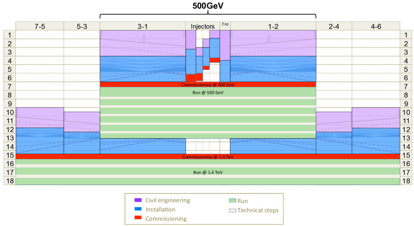
Construction start for CLIC could be around 2023 after an initial Project Preparation Phase 2017–2022. During the Preparation Phase it is essential to optimise the component performances and to reduce their cost, in preparation of large industrialization contracts. In addition, a number of key system performances need to be addressed to minimise the risk of the CLIC project implementation. In this way requirements can be rationalized by understanding the interplay between safety margins and therefore the overall project cost can be reduced. The drive beam and luminosity performances, in particular, are best addressed in larger system tests. The currently foreseen timeline for the CLIC project preparation and stage 1 construction is shown in Figure 4, with details presented in [CLICCDR_vol3].
Construction schedules (Figure 5) are essentially driven by civil engineering, infrastructure and machine installation. Production of the large-series components proceeds at rates such that they become available for installation as soon as preceding construction activities allow it. In the first stage, construction of the injector complex, experimental area and detectors just matches the construction time for the main linacs, thus allowing commissioning with beam to start in year 7. This would allow completion of the stage 1 project by 2030 when the LHC programme reaches a natural completion. In order to minimize interruption of operation for physics, civil engineering and series component production for the second stage must re-start in year 10, thus allowing commissioning in year 15 (scenario A): this can be achieved without interference with operation for physics in the first stage.
6 Luminosity goals and possible overall project timeline for CLIC
With the recent discovery of a new Higgs-like state at GeV at LHC and considering the importance of studies near the top threshold, it is evident that an initial CLIC stage at 375 GeV will already provide exceptional physics. A second stage around 1.2–1.5 TeV would allow for measurements of other Higgs properties, such as the top-Yukawa coupling, the Higgs self-coupling and rare Higgs decay modes. With the present knowledge a third stage well beyond 1.5 TeV can only be justified by the general arguments of improved production cross-sections and precision on the measurements mentioned above, and a significantly increased search capability. It is however important to keep in mind that the very recent results from LHC open a completely new experimental territory. We can look forward to more LHC results from the 2012 data-analyses and in particular when LHC moves to full energy running in 2015, potentially providing even more exciting prospects for a future CLIC programme, including ultimate energy stages beyond 1.5 TeV.
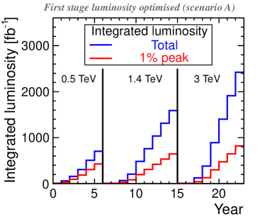
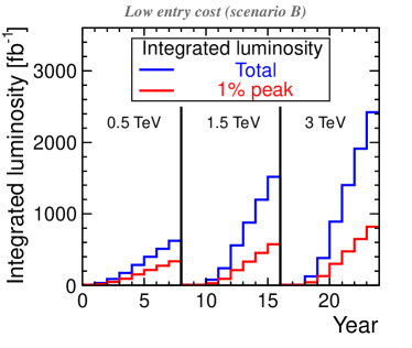
The CLIC project as outlined is an ambitious long-term programme, with an initial 7 year construction period and three energy stages each lasting 6–8 years to achieve the integrated luminosity goals, interrupted by 2 year upgrade periods. Possible operating scenarios for the complete CLIC programme are sketched in Figure 6: the duration of each stage is defined by the integrated luminosity targets of 500 fb-1 at 500 GeV, 1.5 ab-1 at 1.4 (1.5) TeV and 2 ab-1 at 3 TeV collision energy. The integrated luminosity in the first stage can be obtained for scenario B by operating for two more years; this is partly regained in the next stage, so that the overall duration of the three-stage programme is comparable for both cases, about 24 years from start of operation.
7 Technology applications
Several of the central technologies in the CLIC project have applications for and are being developed with other communities. The most important examples of the use of high-gradient normal-conducting technology developed for CLIC are:
-
•
The development of compact linacs for proton and carbon ion cancer treatment, e.g. the TULIP proposal of the TERA project [c:TULIP].
-
•
Future free electron lasers (FELs) for photon-science, which encompasses biology, chemistry, material science and many other fields. Common developments have been made with the SWISS FEL [c:SWISSFEL] and the ZFEL [c:ZFEL] and further collaborations with several other projects are being prepared.
-
•
Compton-scattering gamma ray sources providing MeV-range photons for laser-based nuclear physics (nuclear-photonics) and fundamental processes (QED studies for example) [c:ELI]. There are also potential applications such as nuclear resonance fluorescence for isotope detection in shipping containers and mining.
Also synchrotron-based light sources and the CLIC damping rings share similar issues and challenges, which are addressed in a collaborative effort.
References
- [1] Physics at the CLIC Linear Collider, 2013, submitted to the 2013 Snowmass process, https://edms.cern.ch/document/1277977
- [2] CLIC Linear Collider Studies, 2012, eds. D. Dannheim, P. Lebrun, L. Linssen, D. Schulte, F. Simon, S. Stapnes, N. Toge, H. Weerts, J. Wells, submitted to the update process of the European Strategy for Particle Physics, arXiv:1208.1402
- [3] The Physics Case for an Linear Collider, 2012, eds. J. Brau, R. Godbole, F. Le Diberder, M. Thomson, H. Weerts, G. Weiglein, J. Wells, H. Yamamoto, submitted to the update process of the European Strategy for Particle Physics, ILC ESD-2012/4, CLIC-Note-949, arXiv:1210.0202
- [4] A Multi-TeV Linear Collider based on CLIC Technology: CLIC Conceptual Design Report, 2012, eds. M. Aicheler, P. Burrows, M. Draper, T. Garvey, P. Lebrun, K. Peach, N. Phinney, H. Schmickler, D. Schulte and N. Toge, JAI-2012-001, KEK Report 2012-1, PSI-12-01, SLAC-R-985, https://cds.cern.ch/record/1500095
- [5] Physics and Detectors at CLIC: CLIC Conceptual Design Report, 2012, eds. L. Linssen, A. Miyamoto, M. Stanitzki and H. Weerts, ANL-HEP-TR-12-01, CERN-2012-003, DESY 12-008, KEK Report 2011-7, arXiv:1202.5940
- [6] The CLIC Programme: towards a staged Linear Collider exploring the Terascale, 2012, eds. P. Lebrun, L. Linssen, A. Lucaci-Timoce, D. Schulte, F. Simon, S. Stapnes, N. Toge, H. Weerts, J. D. Wells, ANL-HEP-TR-12-51, KEK Report 2012-2, MPP-2012-115, arXiv:1209.2543
- [7] N. Phinney, N. Toge and N. Walker (editors), International Linear Collider Reference Design Report, Volume 3 - Accelerator, 2007, arXiv:0712.2361
- [8] A. Degiovanni et al., TERA high gradient test program of RF cavities for medical linear accelerators, Nucl. Instrum. Methods, A657 (2011) (1), 55–58, 10.1016/j.nima.2011.05.014
- [9] http://www.psi.ch/swissfel/
- [10] http://www.rug.nl/kvi/facilities/zfel/
- [11] http://www.eli-np.ro/