Interplay between spin-orbit interactions and a time-dependent electromagnetic field in monolayer graphene
Abstract
We apply a circularly and linearly polarized terahertz field on a monolayer of graphene taking into account spin-orbit interactions of the intrinsic and Rashba types. It turns out that the field can be used not only to induce a gap in the energy spectrum, but also to close an existing gap due to the different reaction of the spin components with circularly polarized light. Signatures of spin-orbit coupling in the density of states of the driven system can be observed even for energies where the static density of states is independent of spin-orbit interactions. Furthermore it is shown that the time evolution of the spin polarization and the orbital dynamics of an initial wave packet can be modulated by varying the ratio of the spin-orbit coupling parameters. Assuming that the system acquires a quasi stationary state, the optical conductivity of the irradiated sample is calculated. Our results confirm the multi step nature of the conductivity obtained recently, where the number of intermediate steps can be changed by adjusting the spin-orbit coupling parameters and the orientation of the field.
pacs:
71.70.Ej, 73.22.Pr, 78.67.WjI Introduction
Since a monolayer of graphite was isolated and detected for the first time,Novoselov_2004 many theoretical and experimental studies on this remarkable and surprising material have been published.Neto_2009 Even several years after its discovery graphene remains one of the most intense research topics in solid state physics. This expresses the high expectations and hopes physicists have for graphene as being a building block for novel electronic devices.
While in the beginning the focus of graphene research was mainly set on spin-independent phenomena, as it was claimed that spin-orbit interactions (SOIs) are virtually unimportant in graphene,Kane_2005 ; Gmitra_2009 recent experimental and theoretical works have demonstrated that spin-orbit coupling (SOC) effects might be important as the characteristic parameters can be enlarged significantly. Neto09 ; Weeks_2011 ; Ma_2012 ; Dedkov_2008 ; Varykhalov_2008 ; Jin_2012 This, in principle, opens up the possibility of using spin-related phenomena in this outstanding material with exceptional electronic properties. Moreover, and indeed fortunately, graphene is not the only promising two-dimensional hexagonal system and thus many of the findings of spin-related research in graphene can also be applied to other systems. As an example we mention a monolayer of MoS2Mak_2010 ; Radis_2011 ; Zeng_2012 which can at low energies effectively be described as two uncoupled gapped graphene systems, where both the band gap and the SOIs turn out to be large, Xiao_2012 ; Li_2012 ; Kormanyos_2013 and silicene, a two-dimensional honeycomb lattice made of silicon atoms.Liu_2011 ; Chen_2012 ; Vogt_2012 Furthermore, restricting ourselves to nearest-neighbor and interlayer hopping, the Hamiltonian of bilayer graphene is formally equivalent to that of monolayer graphene with a purely Rashba SOC, where the Rashba coefficient is substituted by the interlayer hopping constant.
In recent works the effects of an external time-dependent field on two-dimensional materials such as a monolayer Calvo_2011 ; Oka_2009 ; Oka_2011 ; Zhou_2011 ; Busl_2012 ; Lopez_2012 ; Calvo_2012 ; Delplace_2013 or bilayerMorell_2012 of graphene, HgTe/CdTe quantum wells,Lindner_2011 ; Cayssol_2012 or n- and p-doped electron gasesFujita_2003 ; Cheng_2005 ; Jiang_2008 ; Zhou_2008 have been discussed. It was shown that an electromagnetic field can induce gaps in the energy spectrum of grapheneCalvo_2011 ; Oka_2009 ; Oka_2011 ; Zhou_2011 and even move and merge the Dirac points.Delplace_2013 Both aspects might be interesting for future applications such as transistors. Furthermore, in Ref. Lindner_2011 the possibility of changing the topology of a HgTe/CdTe quantum well by applying linearly polarized light leading to so-called Floquet topological insulators has been reported.
In this work we study how SOIs of the intrinsic and Rashba types manifest themselves in a monolayer of graphene under the influence of a time-dependent field whose energy is on the terahertz (THz) regime. The SOC coupling constants are chosen to be of the order of the photon energy. This work is organized as follows. In Sec. II, we introduce the model Hamiltonian and briefly summarize the main properties of the solution of Schrödinger’s equation according to Floquet’s theorem. In Sec. III, the energy spectrum and the density of states (DOS) of the driven system is discussed and signatures arising from the interplay of SOC and the THz field are pointed out. In Sec. IV, the dynamics of physical observables such as the spin polarization and the position operators are studied. In Sec. V, the optical conductivity of the irradiated sample is calculated for various combinations of the SOC parameters. Finally, Sec. VI summarizes the main results of this work.
II The model
We use the Kane-Mele modelKane_2005 (setting throughout this work)
| (1) |
to describe a monolayer of graphene including SOIs of the intrinsic () and Rashba () types at one point. The Pauli matrices () and the unit matrix () act on the pseudospin (real spin) space. The other point can be described by the above Hamiltonian with and . The effect of the electromagnetic field can be incorporated by the minimal coupling scheme . As the vector potential does not depend on the position operators, the Hamiltonian remains diagonal in momentum space and we can treat as a number instead of a differential operator. The time-dependent contribution to the Hamiltonian,
| (2) |
is assumed to be periodic in time, i.e., , where and is the frequency of the radiation field.
The vector potential describing a monochromatic wave propagating perpendicular to the graphene plane can be assumed to be either classical,
| (3) |
or quantized,
| (4) |
where, among obvious notation, the parameter contains geometric information about the cavity surrounding the system. The field is either circularly () or linearly polarized (e.g., along the direction for ). Quantizing the electromagnetic field adds a degree of freedom described by the bosonic operators , which comes along with a new conserved quantity given by the helicity , where the angular momentum generates rotations of the carrier degrees of freedom in real and pseudospin space. To treat the electromagnetic field as a quantized operator is important in situations where the charge carriers have a significant back-action on the field which in turn can alter the particle dynamics itself.
To analyze this aspect further, let us consider the case of a vanishing field and neglect SOIs for the moment. Now assuming a wave packet with initial momentum along the axis and the pseudospin initially in the direction, the dynamics of the system in the Heisenberg representation is given by Schliemann_2005 ; Schliemann_2006 ; Schliemann_2007 ; Schliemann_2008 ; David_2006 ; Trauzettel_2007 ; David_2010
| (5) |
and . From the classical expression for the radiative power of dipolar radiation,Landau_Fields , we find the time-averaged energy loss per time as
| (6) |
i.e., for a wave vector of nm-1 the radiative power is of order meV/ps. Due to the very large Fermi velocity of m/s in graphene, a time scale of 1 ps corresponds, for appropriate initial conditions, to a distance of 1 m traveled by the wave packet. Therefore, the above loss rate should be seen as a small effect.Note_Quantization_in_2DEG Hence the energy loss due to dipolar radiation induced by Zitterbewegung can be neglected compared to other energy scales in typical experimental situations. Accordingly, in what follows we will treat the electromagnetic field as a classical quantity and not as an operator. For convenience we introduce the dimensionless quantity .
Due to the periodicity of , the solution of Schrödinger’s equation obeys Floquet’s theoremGrifoni_1998 ; Kohler_2005 and thus is of the form
| (7) |
where are band indices. The Floquet states have the same periodicity as the Hamiltonian and can be expanded in a Fourier series:Shirley_1965
| (8) |
The original problem can now be reduced to the diagonalization of the time-independent Floquet Hamiltonian whose components are defined by
| (9) |
The time evolution of an arbitrary state with respect to an initial time is captured by the operator
| (10) |
Notice that the energies and wave functions entering Eq. (7) are not uniquely defined as (with ) is a solution of Schrödinger’s equation as well. The corresponding quasienergy differs only by a multiple of the THz energy. Hence the choice of the eigenenergies is ambiguous as they describe the same physical situation. In order to get a well-defined quantity that is the same for all , we furthermore introduce the time-averaged (or quasi stationary) energyHsu_2006 ; Faisal_1996 ; Gupta_2003 ; Zhou_2011
| (11) |
In general, there is a non trivial relation between the quasienergies and the mean energies. Notice that in the absence of the driving Eq. (11) reproduces the energies of the unperturbed system (see below).
III Energy spectrum and density of states
III.1 Energy bands
The energy bands of the static problem () can readily be obtained:
| (12) |
For a finite driving, the eigensystem is calculated numerically by diagonalization of the Floquet Hamiltonian in Eq. (9). As mentioned above, this leads to an infinite number of eigenenergiesShirley_1965 where only four of them are physically independent (corresponding to the dimension of the problem), while all others can be obtained by adding or subtracting a multiple of the energy of the electromagnetic field .
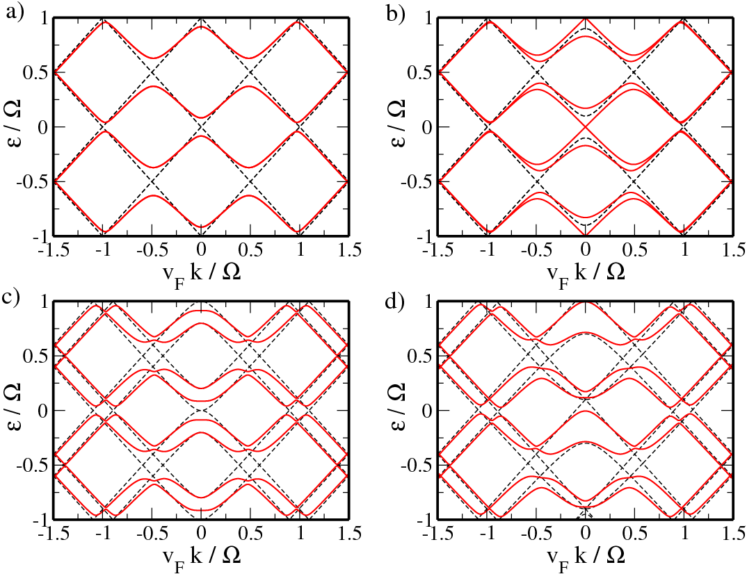
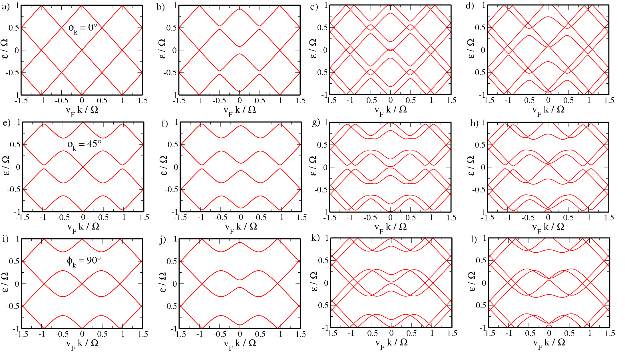
In Figs. 1 and 2 the quasienergies within the first and second Brillouin zones (BZs) are shown as red lines for different combinations of the SOC parameters for a fixed field strength of . The black dashed line in Fig. 1 shows, for comparison, Eq. (12) projected to the BZ. The SOC parameters are chosen to be of the order of the THz energy, e.g., in the present case . As mentioned in the introduction, it has been demonstrated that and can be enlarged by several orders of magnitude by choosing proper adatomsNeto09 ; Weeks_2011 ; Ma_2012 or a suitable environmentDedkov_2008 ; Varykhalov_2008 ; Jin_2012 which allows values of and in the THz (meV) range. Our results depend only on the ratio and on the coupling strength . Hence they may also be applied to fields with larger frequencies (such as the mid-infrared) provided the SOC parameters are large enough. The advantage of a THz field, however, is that the field energies are far below the energies of optical phonons (of about meV),Ando_2007 such that excitations of optical phonons are suppressed.
Circular polarization. The unperturbed energy spectrum of Eq. (12) consists of twofold spin-degenerate bands if , while for a finite Rashba coefficient structure inversion symmetry is broken and the bands split up; see the dashed lines in Fig. 1. Once is turned on, in Figs. 1(a), 1(c) and 1(d) a gap opens up right the Dirac point, separating the valence and conduction bands. Here the bands are parabolic around the K point but closely follow the linear behavior of the unperturbed result for . Similarly, a finite gap also appears in the mean energies lifting the K point degeneracy, e.g., in Fig. 3(a) with a gap of . For finite SOIs the bands react differently on the THz field and hence the degeneracy present in the static case of Fig. 1(b), where and , disappears. Right at the Dirac point the quasienergy gap vanishes, while a new gap opens up between the conduction (or valence) band states with different spin orientations. Two of the four bands are now linear and not parabolic as in the case of . Similarly, the gap in the time-averaged energies shown in Fig. 3(b) is closed. For larger momenta, , the spin splitting in Fig. 3(b) eventually becomes so small that the bands are virtually degenerate again.
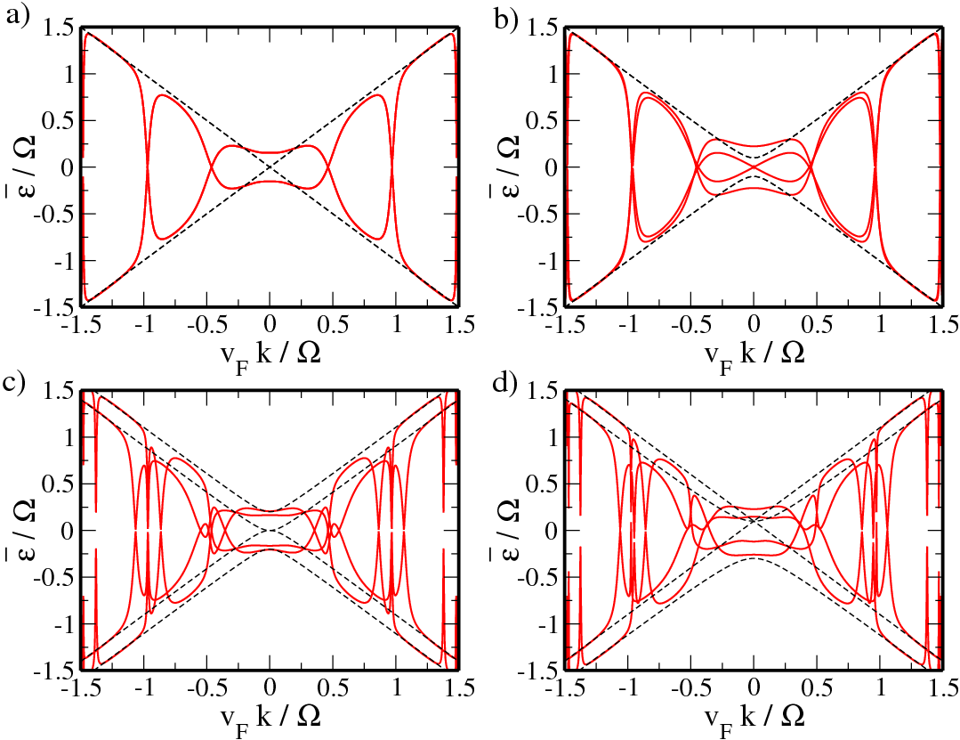
From Fig. 1 we can see that besides the gap at the Dirac point, additional gaps appear at (). While these gaps are quite large for and , its value strongly decreases for larger momenta and seems to vanish for . The reason for these gaps is the existence of photon resonances,Zhou_2011 i.e., the absorption and emission of photons, similar to the ac Stark effect in semiconductors.Grifoni_1998 Here transitions might occur at the resonant points . In the vicinity of the resonances, , the average energies drop to zero. For large enough momenta the dips eventually become so narrow that they seem to disappear. In case spin degeneracy is broken (i.e., ), the above resonant condition can be fulfilled for multiple values of and hence we observe not one but several nearby dips in the average energy spectrum, as shown in Figs. 3(c) and 3(d).
Linear polarization. If the field is linearly polarized, in the following along the direction, the energy spectrum is expected to be strongly anisotropic. In contrast to the circular case spin degeneracy is broken only if .
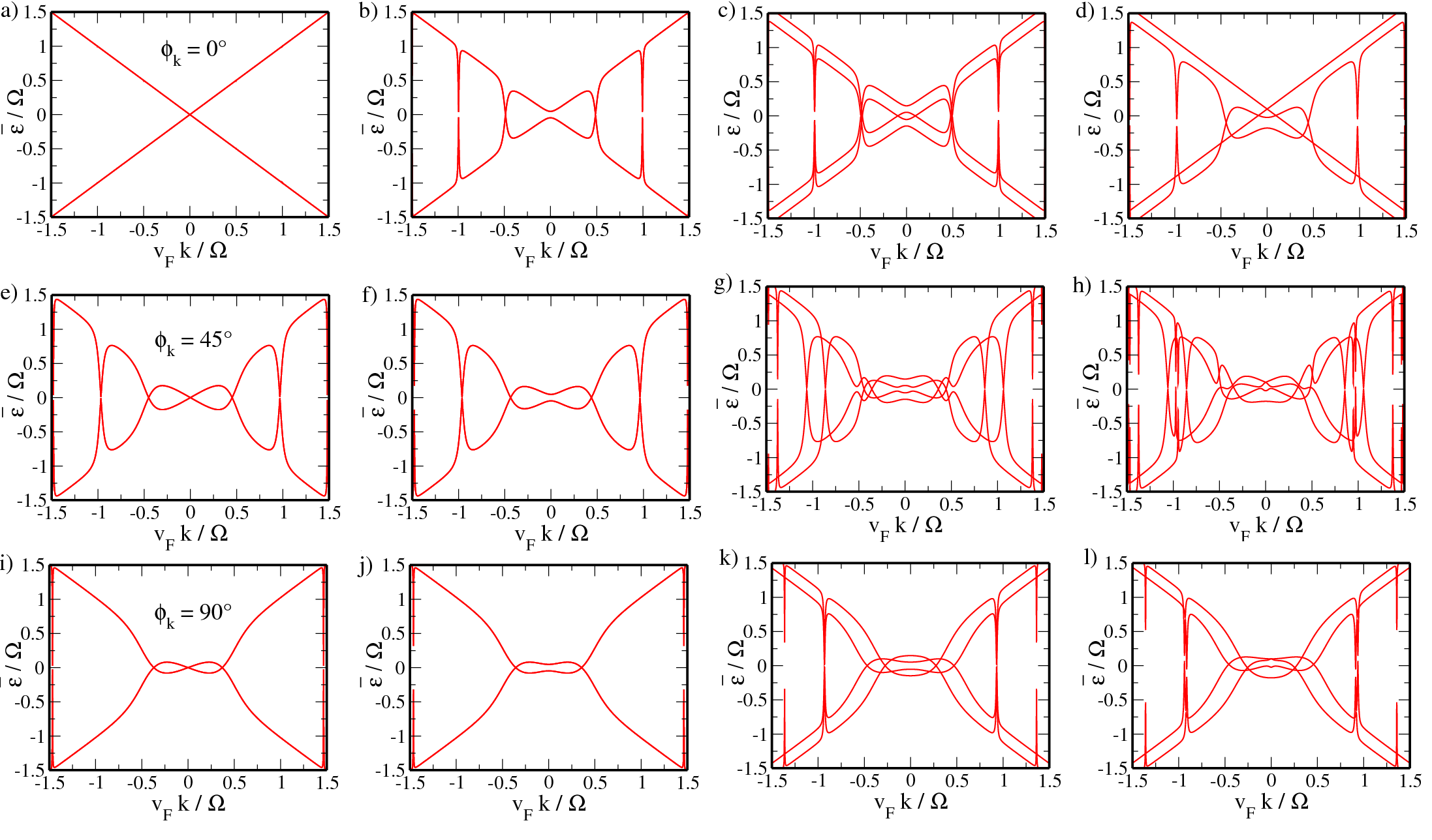
From Fig. 2(a) we can see that for and the quasienergy spectrum for an in-plane angle of , where , exactly follows the unperturbed spectrum, i.e., the field has no influence.Zhou_2011 However, if at least one of the SOC parameters is finite, the valence and conduction bands no longer touch at , where deviations from the static results are largest, and the THz field induces a gap as shown in Fig. 2(b). The corresponding time-averaged energies, shown in Figs. 4(b)-4(d), exhibit characteristic dips at , as for circularly polarized light. However, from Figs. 4(a) and 4(d) we can see that only those bands are affected by the THz field that are (in the static limit) not linear but parabolic in momentum while the linear bands remain unchanged and in particular ungapped. Notice that contrary to the above case where the positions of the dips in the average energies are nearly the same for both spin orientations.
For (see the middle row of Fig. 2), we observe remarkable gaps in all quasienergy spectra at and . In addition, for finite SOIs an additional small gap opens up at the K point separating the valence and conduction bands; see Figs. 2(g) and 2(h). The time-averaged energies as shown in the middle row of Fig. 4 resemble the circular result of Fig. 3. The important differences, however, are the absence [Figs. 4(e) and 4(h)] or reduction [Figs. 4(f) and 4(g)] of the gap at the Dirac point and the fact that the THz does not cause an additional spin splitting of the bands; compare Fig. 1(b) and Fig. 2(f). In contrast to the case of the positions of the resonant dips clearly split up for .
Finally, for an in-plane angle perpendicular to the polarization direction, i.e., , again in all four cases a distinct gap opens up at . While for the K point energies do not change, a small gap opens up in the quasienergies in Figs. 2(k) and 2(l) where . Furthermore, the dips in the mean energies of cases Figs. 4(i) and 4(j) are suppressed for but they are clearly present in Figs. 4(k) and 4(l).
III.2 Density of states
In Figs. 5 and 6 the time-averaged DOS,Zhou_2011
| (13) |
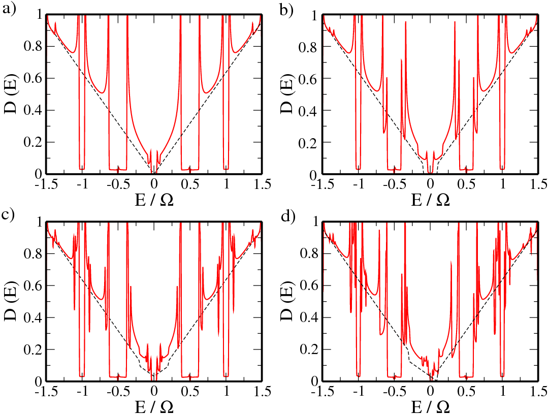
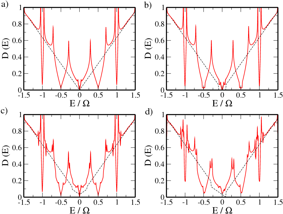
is shown for various combinations of the SOC parameters with (red solid line) and without (black dashed) electromagnetic field for circularly and linearly polarized light, respectively. The field amplitude was set to . The prefactor is due to the valley degeneracy.
The static DOS for zero energy, shown as the dashed lines in Figs. 5 and 6, is zero in (a) and (b) and finite in (c) and (d). In the latter case () the charge neutrality point is shifted to . The electromagnetic field yields a finite weight to the subbands in the first BZ even for momenta . This leads to a distinct increase of the DOS for small energies compared to the field-free situation.Calvo_2011 In Fig. 6(b), for example, the DOS is greatly enhanced for , while in the static case in this regime.
As the quasienergies have several extrema located at and (see Figs. 1 and 2), the DOS exhibits pronounced Van Hove singularities.Zhou_2011 ; Calvo_2011 While due to the isotropy of the quasienergy spectrum in the case of circularly polarized light these singularities occur for arbitrary angles of , for a linearly polarized field not all angles lead to Van Hove singularities. As a consequence, the associated peaks rise much more strongly for compared to . In the former, the DOS drops down almost vertically and remains roughly constant around and . This is in clear contrast to the linearly polarized case, where the decrease of the DOS is much smoother and the DOS becomes peaked, with being roughly linear around and .Morell_2012 Moreover, if spin degeneracy is lifted, the DOS shows additional dips in between neighboring Van Hove singularities. This is also true in Fig. 5(b), where the splitting is caused by the THz field and not by the Rashba term.
In the static limit signatures of SOIs in the DOS can be seen only in a narrow region with , while for larger energies it is virtually the same in all cases (see the dashed lines in Figs. 5 and 6). This changes once the field is switched on. Here SOC manifests itself even for larger energies. Comparing, e.g., Figs. 5(a) and 5(c), we see a remarkable difference even for energies due to the additional dips and peaks in the DOS. This can be understood from the quasienergy spectrum, e.g., in Fig. 1(c), where due to the breaking of spin degeneracy several nearby points with a horizontal dispersion exist. For circularly polarized light qualitatively the same happens also for the case of a purely intrinsic coupling () as the bands split up for . However, this splitting is significant only for small momenta and hence the multiple dips in Fig. 5(b) can be seen only for energies around .
IV Spin polarization and wave packet dynamics
We now discuss the dynamics of the real spin expressed by the operator (). We restrict ourselves to an initial state described by a Gaussian wave packet for a single momentum,Schliemann_2008 which is appropriate for a sufficiently broad initial wave packet:Schliemann_2007
| (14) |
In the following the spinor components in Eq. (14) are chosen as , i.e., the initial state is in general a linear combination of the static eigenvectors. Because of
changes in the initial out of plane spin polarization (SP)
where , can be induced only if the Rashba contribution is finite. Similarly, for the other two spin directions,
and
whose dynamics are described by
at least one of the SOC coefficients has to be nonzero in order to get a nontrivial time evolution. In the following we set without loss of generality .
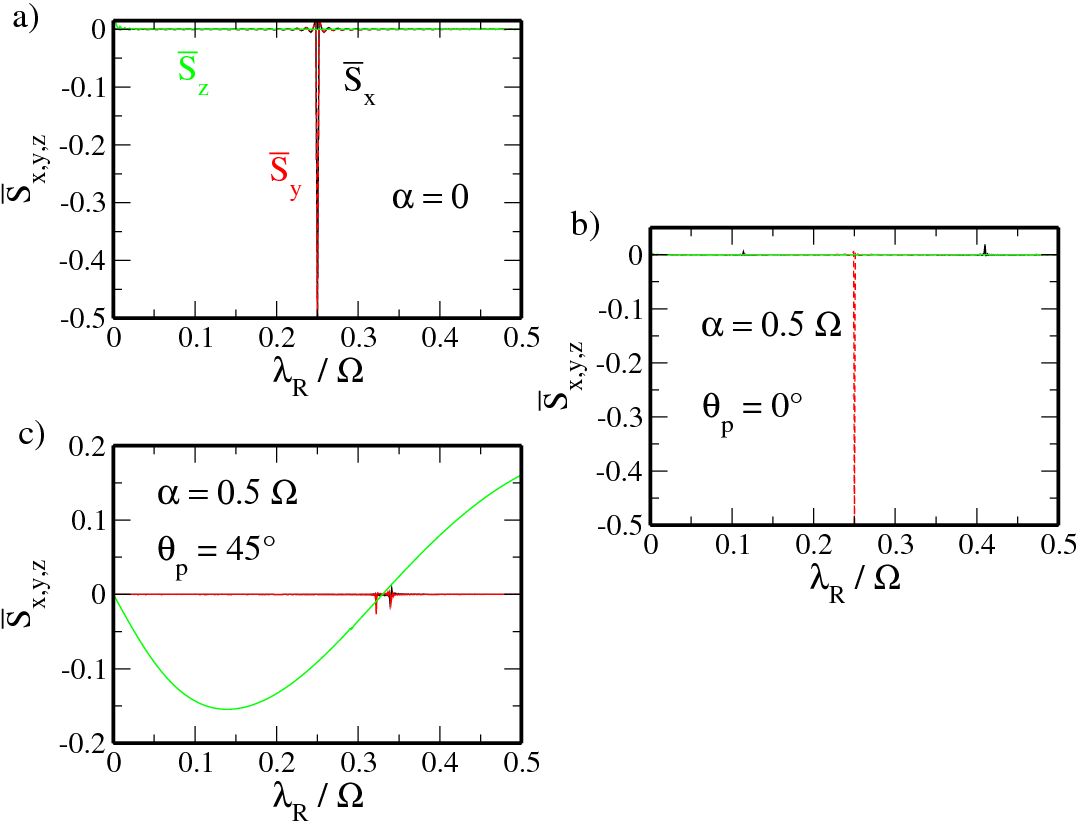
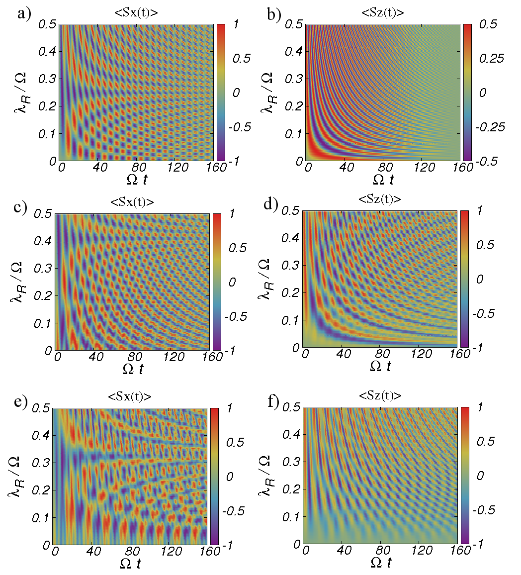
In Fig. 7 we fix the intrinsic parameter and vary the Rashba constant at the Dirac point. The field strength is set to . While for the in plane SP of the static system, exemplarily shown for the component in Fig. 7(a), shows fast oscillations around zero; right at the point the expectation values and oscillate around a finite value. Subsequently the mean polarization shown as black and red lines in Fig. 8(a), calculated for a total simulation time of , vanishes or is very small for , while for . If we now turn on the THz field, the time evolution of the spin operators clearly becomes more complicated; see Figs. 7(c) and 7(e). If the field is linearly polarized along the direction, is finite only for , with at that point, as in the static case. However, this is no longer true for as can be seen from Fig. 8(b) where the peak for the component disappears. For circularly polarized light both the peaks for and at vanish and a significantly reduced dip at appears. The out-of-plane SP () of the static system oscillates around zero, where the period of the oscillations increases for larger ; see Fig. 7(b). Hence in contrast to the mean polarization vanishes for arbitrary , as can be seen from the green line in Fig. 8(a). This remains true for linearly polarized light where in all cases. Compared to that the situation for circularly polarized light is quite different. Here the component of the averaged spin oscillates as a function of and, depending on the magnitude of the Rashba parameter, can be either positive or negative or zero for and . Notice that even though the intrinsic parameter has been fixed to in the above discussion, our findings remain qualitatively the same for other values of , and in particular the peak, e.g., in Fig. 8(a) always appears right at the point where . A possible way to detect the SP has been described in Ref. Rugal_2004 . Here the sample is scanned by a cantilever in magnetic resonance force microscopy, where the detected shift in frequency turns out to be related to the SP.
The time evolution of the position operators in Heisenberg representation is given by
| (15) |
Note that contrary to electron and hole gas systemsSchliemann_2005 ; Schliemann_2006 ; Schliemann_2007 the dissipative term proportional to momentum is missing in Eq. (15) due to the Dirac-like nature of the charge carriers in graphene. By calculating the usual velocity operator it is thus possible to extract the orbital dynamics of the system,
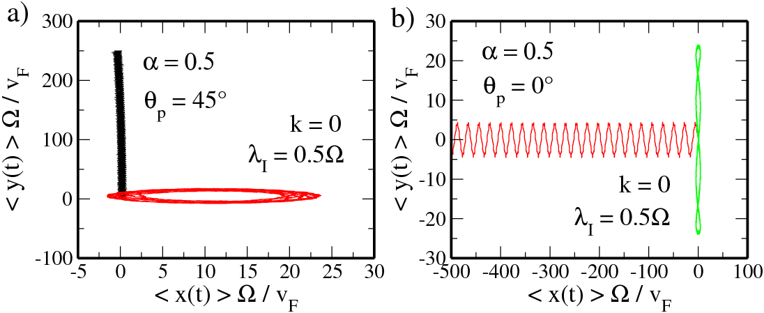
with respect to an initial wave packet given in Eq. (14). In Fig. 9 this is shown for circularly (a) and linearly (b) polarized light of strength for fixed and two different values of the Rashba SOC parameters for a total simulation time of . While for and the trajectory resembles an ellipse, and hence the particle becomes localized, as exemplarily shown in the red curve in Fig. 9(a) for , the basic propagation is along the direction if the Rashba contribution vanishes and, compared to , only moderate deviations from the initial position in the direction can be seen.
For and [see the red curve in Fig. 9(b)], the main dynamics is along the axis with small oscillations around , while in the other case of (green line) the trajectory is again bounded in a finite region around and , respectively.
V Optical conductivity
In this section the optical conductivity of irradiated graphene is calculated. As we are not interested in processes that appear right after or before the THz field is turned on and off, we consider the system in a quasi stationary state and assume the probability distribution to be of the form , where are the average energies introduced in Eq. (11) and the inverse temperature. The quasi equilibrium density matrix in the basis of the Floquet states then readsZhou_2011 ; Gupta_2003 ; Faisal_1996 ; Hsu_2006 . In the following, we restrict ourselves to zero temperature such that the Fermi distribution function reads , with being the chemical potential. The expression for the dissipative part of the time-averaged longitudinal optical conductivity, obtained from the nonequilibrium Green’s function method derived in Ref. Zhou_2011 , then reads
| (16) |
The quasienergies and states entering Eq. (16) are chosen to be in the first BZ, although any other choice is possible as well. From the function in Eq. (16) we can see that, in principle, transitions between all kinds of subbands are possible. In the static limit only those subbands that correspond to the energies of Eq. (12) have a nonzero weight and Eq. (16) reproduces previous results.Stauber_2008 ; Ingenhoven_2010 ; Scholz_2011 For a finite driving the weight of the other subbands becomes nonzero, whereas it increases for larger driving amplitudes, and hence additional transitions become possible.
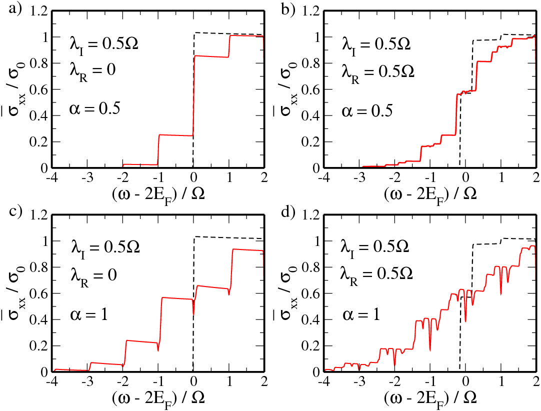
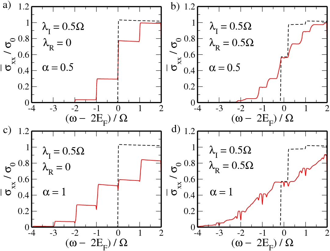
In Figs. 10 and 11 we show the optical conductivity calculated for a fixed Fermi energy of under the influence of circularly and linearly polarized light, respectively. The field strength is , , and . The main feature of the static conductivity, as shown, e.g., in the dashed curve in Fig. 10(a), is its steplike behavior at , where transitions from the valence to the conduction band become possible. Switching on the time-dependent field leads to several additional steps in ,Zhou_2011 due to photon-assisted processes. By comparing e.g., Figs. 10(a) and 10(c), it becomes clear that the number of steps increases for larger coupling strengths as the weight is distributed over a broader range of subbands. The effect of the Rashba term, which leads to a distinct breaking of the spin degeneracy of each subband, furthermore induces several intermediate steps as the number of possible transitions in the function of Eq. (16) becomes much larger. From Figs. 10(b) and 11(b) we can see that the basic structure of is the same for and , but in the latter the conductivity turns out to be slightly smoother. By increasing the field strength to we observe dips in the conductivity at ,Zhou_2011 where the effect is clearly larger for than ; see, e.g., Figs. 10(c) and 11(c). The inclusion of the Rashba term creates further dips for slightly smaller and larger frequencies, respectively. These dips are due to the appearance of gaps in the quasienergy spectrum (see the discussion in Sec. III), as some transitions are no longer possible. From Figs. 10(c) and 10(d) one can see that while the static conductivities (dashed curves) are quite similar in both cases, i.e., the effect of is only slight, remarkable differences occur in the driven case, and hence SOC effects are greatly enhanced.
VI Conclusions
In this work the effect of a time-dependent electric field on a monolayer of graphene including SOIs of the intrinsic and Rashba types has been studied.
We have demonstrated that a circularly polarized THz field can be used not only to induce a gap at the Dirac point, which transforms graphene from a semimetal to an insulator, but also to close an existing gap in the quasienergies. In the opposite case of a linear polarization the spectrum turned out to be highly anisotropic and, depending on the strength of the SOC parameters and on the orientation of the field, gaps in the spectrum might appear at the K point and at the photon resonances , or become suppressed.
While the effect of SOIs on the DOS of the static sample could be seen only for energies , due to the existence of a multiple number of dips, signatures of SOC in the DOS of irradiated graphene appear even at much larger energies.
By introducing a time-dependent field it turned out to be possible to induce a finite net spin polarization in the sample. The sign and magnitude, e.g., of the out-of-plane polarization, can be modulated by changing the ratio of the SOC parameters, which can be done experimentally by adjusting the Rashba coefficient via an electric gate.
In the last part of this work the longitudinal optical conductivity was calculated. As reported already in Ref. Zhou_2011 , the conductivity of irradiated graphene exhibits a multi step structure as transitions between a variety of subbands become possible. The number of steps depends not only on the coupling strength, but also on the magnitude of the Rashba parameter and on the polarization direction. Furthermore, for large enough coupling strengths the conductivity drops down for frequencies around the photon energy.Zhou_2011 As for the DOS, compared to the static result the effect of SOIs on the optical conductivity is greatly enhanced for , which is mainly caused by the Rashba contribution.
Finally, let us point out that even though the SOC parameters within this work have been chosen to be smaller than (but comparable to) the energy of the field, our findings [such as the appearance of gaps in the quasienergy spectrum or the oscillatory behavior of the out-of-plane spin polarization in Fig. 8(c)] are not limited to this case, but can also be observed in the opposite case of .
Acknowledgements.
We thank M. Busl, M. Grifoni, S. Kohler, and M. W. Wu, for useful discussions. This work was supported by Deutsche Forschungsgemeinschaft via Grant No. GRK 1570.References
- (1) K. S. Novoselov, A. K. Geim, S. V. Morozov, D. Jiang, Y. Zhang, S. V. Dubonos, I. V. Grigorieva, and A. A. Firsov, Science 306, 666 (2004).
- (2) For an overview see e.g., A. H. Castro Neto, F. Guinea, N. M. R. Peres, K. S. Novoselov, and A. K. Geim, Rev. Mod. Phys. 81, 109 (2009).
- (3) C. L. Kane and E. J. Mele, Phys. Rev. Lett. 95, 226801 (2005).
- (4) M. Gmitra, S. Konschuh, C. Ertler, C. Ambrosch-Draxl, and J. Fabian, Phys. Rev. B 80, 235431 (2009).
- (5) A. H. Castro Neto and F. Guinea, Phys. Rev. Lett. 103, 026804 (2009).
- (6) C. Weeks, J. Hu, J. Alicea, M. Franz, and R. Wu, Phys. Rev. X 1, 021001 (2011).
- (7) D. Ma, Z. Li, and Z. Yang, Carbon 50, 297-305 (2012).
- (8) A. Varykhalov, J. Sánchez-Barriga, A. M. Shikin, C. Biswas, E. Vescovo, A. Rybkin, D. Marchenko, and O. Rader, Phys. Rev. Lett. 101, 157601 (2008).
- (9) Y. S. Dedkov, M. Fonin, U. Rüdiger, and C. Laubschat, Phys. Rev. Lett. 100, 107602 (2008).
- (10) K.-H. Jin and S.-H. Jhi, Phys. Rev. B 87, 075442 (2013).
- (11) K. F. Mak, C. Lee, J. Hone, J. Shan, and T. F. Heinz, Phys. Rev. Lett. 105, 136805 (2010).
- (12) B. Radisavljevic, A. Radenovic, J. Brivio, V. Giacometti, and A. Kus, Nature Nanotechnology 6, 147 (2011).
- (13) H. Zeng, J. Dai, W. Yao, D. Xiao, and X. Cui, Nature Nanotechnology 7, 490 (2012).
- (14) D. Xiao, G. B. Liu, W. Feng, X. Xu, and W. Yao, Phys. Rev. Lett. 108, 196802 (2012).
- (15) A. Kormányos, V. Zolyomi, N. D. Drummond, P. Rakyta, G. Burkard, and V. I. Fal’ko, Phys. Rev. B 88, 045416 (2013).
- (16) Z. Li and J. P. Carbotte, Phys. Rev. B 86, 205425 (2012).
- (17) C. C. Liu, H. Jiang, and Y. Yao, Phys. Rev. B 84, 195430 (2011).
- (18) L. Chen, C. C. Liu, B. Feng, X. He, P. Cheng, Z. Ding, S. Meng, Y. Yao, and K. Wu, Phys. Rev. Lett. 109, 056804 (2012).
- (19) P. Vogt, P. De Padova, C. Quaresima, J. Avila, E. Frantzeskakis, M. C. Asensio, A. Resta, B. Ealet, and G. Le Lay, Phys. Rev. Lett. 108, 155501 (2012).
- (20) H. L. Calvo, H. M. Pastawski, S. Roche, and L. E. F. Foa Torres, Appl. Phys. Lett. 98, 232103 (2011).
- (21) T. Oka and H. Aoki, Phys. Rev. B 79, 081406 (R) (2009).
- (22) T. Oka and H. Aoki, J. Phys.: Conf. Ser. 200, 062017 (2010).
- (23) Y. Zhou and M. W. Wu, Phys. Rev. B 83, 245436 (2011).
- (24) M. Busl, G. Platero, and A. P. Jauho, Phys. Rev. B 85, 155449 (2012).
- (25) A. Lopez, Z. Z. Sun, and J. Schliemann, Phys. Rev. B 85, 205428 (2012).
- (26) H. L. Calvo, P. M. Perez-Piskunow, S. Roche, and L. E. F. Foa Torres, Appl. Phys. Lett. 101, 253506 (2012).
- (27) P. Delplace, Á. Gómez-León, and G. Platero, arXiv:1304.6272.
- (28) E. Suarez Morell and L. E. F. Foa Torres, Phys. Rev. B 86, 125449 (2012).
- (29) N. H. Lindner, G. Refael, and V. Galitski, Nat. Phys. 7, 490 (2011).
- (30) J. Cayssol, B. Dora, F. Simon, and R. Moessner, Phys. Status Solidi RRL 7, 101 (2013).
- (31) M. Fujita, T. Toyoda, J. C. Cao, and C. Zhang, Phys. Rev. B 67, 075105 (2003).
- (32) J. L. Cheng and M. W. Wu, Appl. Phys. Lett. 86, 032107 (2005).
- (33) J. H. Jiang, M. W. Wu, and Y. Zhou, Phys. Rev. B 78, 125309 (2008).
- (34) Y. Zhou, Physica E 40, 2847 (2008).
- (35) J. Schliemann, D. Loss, and R. M. Westervelt, Phys. Rev. Lett. 94, 206801 (2005).
- (36) J. Schliemann, D. Loss, and R. M. Westervelt, Phys. Rev. B 73, 085323 (2006).
- (37) J. Schliemann, Phys. Rev. B 75, 045304 (2007).
- (38) J. Cserti and G. David, Phys. Rev. B 74, 172305 (2006).
- (39) B. Trauzettel, Y. M. Blanter, and A. F. Morpurgo, Phys. Rev. B 75, 035305 (2007).
- (40) J. Schliemann, New J. Phys. 10, 043024 (2008).
- (41) G. David and J. Cserti, Phys. Rev. B 81, 121417(R) (2010).
- (42) L. D. Landau and E. M. Lifshitz, Classical Theory of Fields (Butterworth-Heinemann (1987), London, 1987).
- (43) It is instructive to compare this result with the situation of Zitterbewegung in a two-dimensional electron gas with SOC of, say, the Rashba type. Here the Hamiltonian reads , where is an effective band mass, and the Rashba parameter is of order eVm. Performing steps analogous to those above, it is easy to see that the radiative power here is given by Eq. (6) when is replaced with m/s and hence . The energy loss due to the dipolar radiation in a two-dimensional electron gas is several orders of magnitude smaller than in graphene and thus a vanishingly small effect.
- (44) M. Grifoni and P. Hänggi, Phys. Rep. 304, 229 (1998).
- (45) S. Kohler, J. Lehmann, and P. Hänggi, Phys. Rep. 406, 379 (2005).
- (46) J. H. Shirley, Phys. Rev. 138, B979 (1965).
- (47) A. K. Gupta, O. E. Alon, and N. Moiseyev, Phys. Rev. B 68, 205101 (2003).
- (48) F. H. M. Faisal and J. Z. Kaminski, Phys. Rev. A 54, R1769 (1996); 56, 748 (1997).
- (49) H. Hsu and L. E. Reichl, Phys. Rev. B 74, 115406 (2006).
- (50) T. Ando, J. Phys. Soc. Jpn. 76, 024712 (2007).
- (51) D. Rugal, R. Budakian, H. J. Mamin, and B. W. Chui, Nature (London) 430, 329 (2004).
- (52) T. Stauber, N. M. R. Peres, and A. K. Geim, Phys. Rev. B 78, 085432 (2008).
- (53) P. Ingenhoven, J. Z. Bernad, U. Zülicke, and R. Egger, Phys. Rev. B 81, 035421 (2010).
- (54) A. Scholz and J. Schliemann, Phys. Rev. B 83, 235409 (2011).