The Degrees of Freedom of the MIMO Y-channel

Anas Chaaban, Karlheinz Ochs, and Aydin Sezgin

This work is supported by the German Research Foundation, Deutsche Forschungsgemeinschaft (DFG), Germany, under grant SE 1697/7. Chair of Communication Systems
Ruhr-Universität Bochum (RUB), Germany
Email: anas.chaaban,karlheinz.ochs,aydin.sezgin@rub.de
Abstract

The degrees of freedom (DoF) of the MIMO Y-channel, a multi-way communication network consisting of 3 users and a relay, are characterized for arbitrary number of antennas. The converse is provided by cut-set bounds and novel genie-aided bounds. The achievability is shown by a scheme that uses beamforming to establish network coding on-the-fly at the relay in the uplink, and zero-forcing pre-coding in the downlink. It is shown that the network has min{2M2+2M3,M1+M2+M3,2N}2subscript𝑀22subscript𝑀3subscript𝑀1subscript𝑀2subscript𝑀32𝑁\min\{2M_{2}+2M_{3},M_{1}+M_{2}+M_{3},2N\} DoF, where Mjsubscript𝑀𝑗M_{j} and N𝑁N represent the number of antennas at user j𝑗j and the relay, respectively. Thus, in the extreme case where M1+M2+M3subscript𝑀1subscript𝑀2subscript𝑀3M_{1}+M_{2}+M_{3} dominates the DoF expression and is smaller than N𝑁N, the network has the same DoF as the MAC between the 3 users and the relay. In this case, a decode and forward strategy is optimal. In the other extreme where 2N2𝑁2N dominates, the DoF of the network is twice that of the aforementioned MAC, and hence network coding is necessary. As a byproduct of this work, it is shown that channel output feedback from the relay to the users has no impact on the DoF of this channel.

I Introduction

Multi-way relay channels have attracted extensive research attention recently, as they constitute an integral part of future networks due to the possibility of employing sophisticated communication techniques (such as network coding) in such networks to increase the spectral efficiency.

This line of research has started with the two-way relay channel which represents the most basic multi-way relay channel. This channel was introduced in [1], and further analyzed in [2, 3, 4, 5, 6]. The capacity region of this channel is known within a constant gap. Recently, the two-way two-relay channel has also been studied and its symmetric capacity approximated in [7]. The multi-way relay channel with more than 2 users was also studied in [8, 9] where each user has 1 message to be multicast to other users, and multi-pair two-way relay channels have been studied in [10, 11].

In this paper, we consider a 3-user MIMO multi-way relay channel, where each user has two messages to be delivered to the two other users. This setup, known as the Y-channel, was introduced by Lee et al. in [12], where it was shown that if the relay has N3M/2𝑁3𝑀2N\geq\lceil{3M/2}\rceil antennas where M𝑀M is the number of antennas at each user, then the cut-set bound given by 3M3𝑀3M DoF is achievable. Contrary to this case, it was shown in [13] that the cut-set bound is not achievable in the SISO Y-channel, and that new bounds are necessary to obtain an approximate characterization of the sum-capacity. In [14], it was noted that the DoF of the general Y-channel with arbitrary number of antennas is still open. This problem is settled in this paper.

The novel contribution of the paper is a complete characterization of the DoF of the MIMO Y-channel. We show that the general MIMO Y-channel with M1M2M3subscript𝑀1subscript𝑀2subscript𝑀3M_{1}\geq M_{2}\geq M_{3} antennas at user 1, 2, and 3, respectively, and with N𝑁N antennas at the relay, has min{2M2+2M3,M1+M2+M3,2N}2subscript𝑀22subscript𝑀3subscript𝑀1subscript𝑀2subscript𝑀32𝑁\min\{2M_{2}+2M_{3},M_{1}+M_{2}+M_{3},2N\} DoF. To show the converse of this result, it is necessary to use genie-aided bounds similar to those in [13]. These novel bounds are essential for characterizing the DoF of the MIMO Y-channel, and cover the opposite case to the one considered by Lee et al. [12]. The genie-aided bounds provide a complete characterization of the DoF of the network when combined with the cut-set bounds [15, 12]. The achievability result is provided by signal-space alignment for network coding in the uplink [12] and zero-forcing pre-coding in the downlink. As a byproduct, it is noted that the DoF can be achieved without using the received signal at each user in the encoding process. This implies that channel output feedback from the relay to the users has no impact on the DoF of this channel.

Throughout the paper, we use bold-face lower and upper case letters for vectors and matrices, respectively, and we use (.)(.)^{\dagger} to denote the transpose of a matrix. 𝐈𝐈\mathbf{I} is the identity matrix, and 𝟎0\mathbf{0} is the zero vector. 𝐱nsuperscript𝐱𝑛\mathbf{x}^{n} is used to denote the sequence (𝐱1,,𝐱n)subscript𝐱1subscript𝐱𝑛(\mathbf{x}_{1},\cdots,\mathbf{x}_{n}). The rest of the paper is organized as follows. In Section II, the system model is introduced and the DoF theorem is stated. In Sections III and IV, the converse and the achievability proof of the Theorem are given, respectively. Finally, we discuss the result in Section V.

II System Model

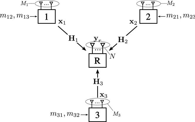
The Y-channel consists of 3 users and a relay as shown in Fig. 1, where each user wants to commmunicate with the other two users. We assume that all nodes are full-duplex and that the channels and signals are real valued. Moreover, the channels are assumed to hold the same value for the duration of the transmission. User j𝑗j has messages mjksubscript𝑚𝑗𝑘m_{jk} and mjlsubscript𝑚𝑗𝑙m_{jl} to be sent to users k𝑘k and l𝑙l, with rates Rjksubscript𝑅𝑗𝑘R_{jk} and Rjlsubscript𝑅𝑗𝑙R_{jl}, respectively, for distinct j,k,l{1,2,3}𝑗𝑘𝑙123j,k,l\in\{1,2,3\}. The transmit signal of user j𝑗j at time instant111The time index i𝑖i will be dropped in the sequel unless necessary i𝑖i is an Mj×1subscript𝑀𝑗1M_{j}\times 1 vector 𝐱j(i)subscript𝐱𝑗𝑖\mathbf{x}_{j}(i). This transmit signal is in general constructed from all the information available at user j𝑗j (messages and observed signals). The received signal at the relay is given by

𝐲r(i)=𝐇1𝐱1(i)+𝐇2𝐱2(i)+𝐇3𝐱3(i)+𝐳r(i),subscript𝐲𝑟𝑖subscript𝐇1subscript𝐱1𝑖subscript𝐇2subscript𝐱2𝑖subscript𝐇3subscript𝐱3𝑖subscript𝐳𝑟𝑖\displaystyle\mathbf{y}_{r}(i)=\mathbf{H}_{1}\mathbf{x}_{1}(i)+\mathbf{H}_{2}\mathbf{x}_{2}(i)+\mathbf{H}_{3}\mathbf{x}_{3}(i)+\mathbf{z}_{r}(i), (1)

which is an N×1𝑁1N\times 1 vector, where 𝐳r(i)subscript𝐳𝑟𝑖\mathbf{z}_{r}(i) is an i.i.d. Gaussian noise vector 𝐳r𝒩(𝟎,𝐈)similar-tosubscript𝐳𝑟𝒩0𝐈\mathbf{z}_{r}\sim\mathcal{N}(\mathbf{0},\mathbf{I}) and 𝐇jsubscript𝐇𝑗\mathbf{H}_{j} is the N×Mj𝑁subscript𝑀𝑗N\times M_{j} random channel matrix from user j𝑗j to the relay. We assume without loss of generality that

M1M2M3.subscript𝑀1subscript𝑀2subscript𝑀3\displaystyle M_{1}\geq M_{2}\geq M_{3}. (2)

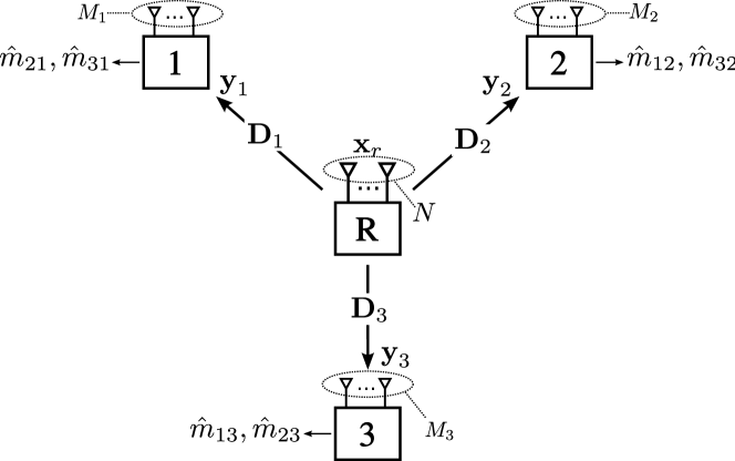
The relay uses its observations up to time instant i1𝑖1i-1 to construct 𝐱r(i)subscript𝐱𝑟𝑖\mathbf{x}_{r}(i). The received signal at user j𝑗j is given by

𝐲j(i)=𝐃j𝐱r(i)+𝐳j(i),subscript𝐲𝑗𝑖subscript𝐃𝑗subscript𝐱𝑟𝑖subscript𝐳𝑗𝑖\displaystyle\mathbf{y}_{j}(i)=\mathbf{D}_{j}\mathbf{x}_{r}(i)+\mathbf{z}_{j}(i), (3)

which is an Mj×1subscript𝑀𝑗1M_{j}\times 1 vector, where 𝐳j(i)subscript𝐳𝑗𝑖\mathbf{z}_{j}(i) is an i.i.d. Gaussian noise vector 𝐳j𝒩(𝟎,𝐈)similar-tosubscript𝐳𝑗𝒩0𝐈\mathbf{z}_{j}\sim\mathcal{N}(\mathbf{0},\mathbf{I}), and 𝐃jsubscript𝐃𝑗\mathbf{D}_{j} is the Mj×Nsubscript𝑀𝑗𝑁M_{j}\times N downlink channel matrix222For reciprocal channels, 𝐃j=𝐇jsubscript𝐃𝑗superscriptsubscript𝐇𝑗\mathbf{D}_{j}=\mathbf{H}_{j}^{\dagger}. from the relay to user j𝑗j. All nodes have a power constraint P𝑃P. The DoF of message mjksubscript𝑚𝑗𝑘m_{jk} is defined as

djk=limPRjk12log(P),subscript𝑑𝑗𝑘subscript𝑃subscript𝑅𝑗𝑘12𝑃\displaystyle d_{jk}=\lim_{\begin{subarray}{c}P\to\infty\end{subarray}}\frac{R_{jk}}{\frac{1}{2}\log(P)}, (4)

and the sum-DoF denoted by dΣsubscript𝑑Σd_{\Sigma} is the sum of all djksubscript𝑑𝑗𝑘d_{jk}. The following theorem states the DoF of the MIMO Y-channel.

Theorem 1.

The DoF of the MIMO Y-channel with M1M2M3subscript𝑀1subscript𝑀2subscript𝑀3M_{1}\geq M_{2}\geq M_{3} is given by

dΣ=min{2M2+2M3,M1+M2+M3,2N}.subscript𝑑Σ2subscript𝑀22subscript𝑀3subscript𝑀1subscript𝑀2subscript𝑀32𝑁\displaystyle{d_{\Sigma}=\min\{2M_{2}+2M_{3},M_{1}+M_{2}+M_{3},2N\}.} (5)
Remark 1.

The special case of M1=M2=M3=Msubscript𝑀1subscript𝑀2subscript𝑀3𝑀M_{1}=M_{2}=M_{3}=M with N3M2𝑁3𝑀2N\geq\left\lceil\frac{3M}{2}\right\rceil which was studied by Lee et al. in [12] is covered by this theorem, where 3M3𝑀3M DoF can be achieved.

Refer to caption
Figure 1: The MIMO Y-channel in the uplink.

The first and last arguments of the min\min operation in (5) are obtained from novel genie-aided bounds which are essential for complete DoF characterization, whereas the remaining term is obtained from cut-set bounds. In the derivation of the upper bounds, it is assumed that the users use non-restricted encoders. That is, the transmit signal of each user at time i𝑖i depends not only on the messages, but also on the received signals at this user till time instant i1𝑖1i-1. This received signal can be considered as channel output feedback, i.e., a feedback of 𝐲r(1),,𝐲r(i1)subscript𝐲𝑟1subscript𝐲𝑟𝑖1\mathbf{y}_{r}(1),\cdots,\mathbf{y}_{r}(i-1). On the other hand, the transmission scheme used to show the achievability of this theorem does not make use of the received signals at each user for encoding. This means that channel output feedback does not have any influence on the DoF of this network. The following sections are devoted for the proof of this Theorem 1.

III Upper Bounds

In this section, we prove the converse of Theorem 1. For this purpose, we need two types of bounds: the cut-set bounds [15], and genie-aided bounds. We start with the cut-set bounds.

Refer to caption
Figure 2: The MIMO Y-channel in the downlink.

III-A Cut-set Bounds

In [12], Lee et al. derived cut-set bounds for the MIMO Y-channel with equal number of antennas at all users. Next, we generalize these bounds for arbitrary number of antennas. By considering information flow from user 1 to all other users and using the cut-set bounds, we can bound the rates of the corresponding messages as follows

R12+R13subscript𝑅12subscript𝑅13\displaystyle R_{12}+R_{13} I(𝐱1;𝐲2,𝐲3,𝐲r|𝐱2,𝐱3),absent𝐼subscript𝐱1subscript𝐲2subscript𝐲3conditionalsubscript𝐲𝑟subscript𝐱2subscript𝐱3\displaystyle\leq I(\mathbf{x}_{1};\mathbf{y}_{2},\mathbf{y}_{3},\mathbf{y}_{r}|\mathbf{x}_{2},\mathbf{x}_{3}), (6)
R12+R13subscript𝑅12subscript𝑅13\displaystyle R_{12}+R_{13} I(𝐱1,𝐱r;𝐲2,𝐲3|𝐱2,𝐱3).absent𝐼subscript𝐱1subscript𝐱𝑟subscript𝐲2conditionalsubscript𝐲3subscript𝐱2subscript𝐱3\displaystyle\leq I(\mathbf{x}_{1},\mathbf{x}_{r};\mathbf{y}_{2},\mathbf{y}_{3}|\mathbf{x}_{2},\mathbf{x}_{3}). (7)

These bounds lead to the following DoF bounds

d12+d13subscript𝑑12subscript𝑑13\displaystyle d_{12}+d_{13} min{M1,N},absentsubscript𝑀1𝑁\displaystyle\leq\min\{M_{1},N\}, (8)
d12+d13subscript𝑑12subscript𝑑13\displaystyle d_{12}+d_{13} min{N,M2+M3},absent𝑁subscript𝑀2subscript𝑀3\displaystyle\leq\min\{N,M_{2}+M_{3}\}, (9)

respectively. Thus, by combining (8) and (9), we get

d12+d13subscript𝑑12subscript𝑑13\displaystyle d_{12}+d_{13} min{N,M1,M2+M3}.absent𝑁subscript𝑀1subscript𝑀2subscript𝑀3\displaystyle\leq\min\{N,M_{1},M_{2}+M_{3}\}. (10)

By applying the same bounding technique to users 2 and 3, we can show that the following upper bound can be obtained

djk+djlsubscript𝑑𝑗𝑘subscript𝑑𝑗𝑙\displaystyle d_{jk}+d_{jl} min{N,Mj,Mk+Ml},absent𝑁subscript𝑀𝑗subscript𝑀𝑘subscript𝑀𝑙\displaystyle\leq\min\{N,M_{j},M_{k}+M_{l}\}, (11)

for distinct j,k,l{1,2,3}𝑗𝑘𝑙123j,k,l\in\{1,2,3\}. By adding the three obtained bounds (for all distinct j,k,l𝑗𝑘𝑙j,k,l), and using M1M2M3subscript𝑀1subscript𝑀2subscript𝑀3M_{1}\geq M_{2}\geq M_{3} (see (2)), we get

dΣsubscript𝑑Σ\displaystyle d_{\Sigma} (12)
min{N,M1,M2+M3}+min{N,M2}+min{N,M3}.absent𝑁subscript𝑀1subscript𝑀2subscript𝑀3𝑁subscript𝑀2𝑁subscript𝑀3\displaystyle\leq\min\{N,M_{1},M_{2}+M_{3}\}+\min\{N,M_{2}\}+\min\{N,M_{3}\}.

III-B Genie-aided Bounds

In [13], genie aided bounds have been derived for the SISO Y-channel. These bounds can be extended to obtain bounds for the general MIMO case. Instead of simply extending the bounds in [13, Lemmas 1 and 2], we provide a different approach to obtain them. This approach gives an insight on how to choose the genie signals needed to derive such bounds.

Assume that every node can obtain its messages with an arbitrarily small probability of error. Using the available information at user 2 for instance, i.e., 𝐲2nsuperscriptsubscript𝐲2𝑛\mathbf{y}_{2}^{n}, m21subscript𝑚21m_{21}, and m23subscript𝑚23m_{23}, user 2 can obtain m12subscript𝑚12m_{12} and m32subscript𝑚32m_{32} reliably. Now, what additional information should be given to user 2 to allow it to decode more messages? Note that after decoding its desired messages, user 2 knows 𝐲2nsuperscriptsubscript𝐲2𝑛\mathbf{y}_{2}^{n}, m21subscript𝑚21m_{21}, m23subscript𝑚23m_{23}, m12subscript𝑚12m_{12}, and m32subscript𝑚32m_{32}. In order to enable user 2 to decode more messages, we should provide it with enough side information which makes it stronger than some other user. Suppose we want to make user 2 stronger than user 3 (which has 𝐲3nsuperscriptsubscript𝐲3𝑛\mathbf{y}_{3}^{n}, m31subscript𝑚31m_{31} and m32subscript𝑚32m_{32}). User 2 already has m32subscript𝑚32m_{32}, thus, if we provide it with 𝐲3nsuperscriptsubscript𝐲3𝑛\mathbf{y}_{3}^{n} and m31subscript𝑚31m_{31}, we make it stronger than user 3, and hence, able to decode m13subscript𝑚13m_{13}. As a result, we can write

n(R12+R32+R13εn)𝑛subscript𝑅12subscript𝑅32subscript𝑅13subscript𝜀𝑛\displaystyle n(R_{12}+R_{32}+R_{13}-\varepsilon_{n})
I(m12,m32,m13;𝐲2n,𝐲3n,m21,m23,m31)absent𝐼subscript𝑚12subscript𝑚32subscript𝑚13superscriptsubscript𝐲2𝑛superscriptsubscript𝐲3𝑛subscript𝑚21subscript𝑚23subscript𝑚31\displaystyle\quad\leq I(m_{12},m_{32},m_{13};\mathbf{y}_{2}^{n},\mathbf{y}_{3}^{n},m_{21},m_{23},m_{31}) (13)
i=1nh([𝐃2𝐃3]𝐱r(i)+[𝐳2(i)𝐳3(i)])+n𝒪(1),absentsuperscriptsubscript𝑖1𝑛matrixsubscript𝐃2subscript𝐃3subscript𝐱𝑟𝑖matrixsubscript𝐳2𝑖subscript𝐳3𝑖𝑛𝒪1\displaystyle\quad\leq\sum_{i=1}^{n}h\left(\begin{bmatrix}\mathbf{D}_{2}\\ \mathbf{D}_{3}\end{bmatrix}\mathbf{x}_{r}(i)+\begin{bmatrix}\mathbf{z}_{2}(i)\\ \mathbf{z}_{3}(i)\end{bmatrix}\right)+n\mathcal{O}(1), (14)

where εn0subscript𝜀𝑛0\varepsilon_{n}\to 0 as n𝑛n\to\infty, and where the second step follows by using standard information-theoretic operations. Here, 𝒪(1)𝒪1\mathcal{O}(1) refers to a term which is irrelevant for DoF characterization. The DoF of m12subscript𝑚12m_{12}, m32subscript𝑚32m_{32}, and m13subscript𝑚13m_{13} is thus upper bounded by the rank of [𝐃2𝐃3]matrixsubscript𝐃2subscript𝐃3\begin{bmatrix}\mathbf{D}_{2}\\ \mathbf{D}_{3}\end{bmatrix} which is min{N,M2+M3}𝑁subscript𝑀2subscript𝑀3\min\{N,M_{2}+M_{3}\} almost surely, thus

d12+d32+d13min{N,M2+M3}.subscript𝑑12subscript𝑑32subscript𝑑13𝑁subscript𝑀2subscript𝑀3\displaystyle d_{12}+d_{32}+d_{13}\leq\min\{N,M_{2}+M_{3}\}. (15)

Now, we try to enhance receiver 1 in such a way that allows it to decode m23subscript𝑚23m_{23}. To do this, we will give 𝐲rnsuperscriptsubscript𝐲𝑟𝑛\mathbf{y}_{r}^{n} and m32subscript𝑚32m_{32} to receiver 1. Thus, after decoding m21subscript𝑚21m_{21} and m31subscript𝑚31m_{31}, receiver 1 will have the observation (𝐲rn,m31,m32)superscriptsubscript𝐲𝑟𝑛subscript𝑚31subscript𝑚32(\mathbf{y}_{r}^{n},m_{31},m_{32}). Note that receiver 3 can decode its desired messages from (𝐲3n,m31,m32)superscriptsubscript𝐲3𝑛subscript𝑚31subscript𝑚32(\mathbf{y}_{3}^{n},m_{31},m_{32}) which is a degraded version of (𝐲rn,m31,m32)superscriptsubscript𝐲𝑟𝑛subscript𝑚31subscript𝑚32(\mathbf{y}_{r}^{n},m_{31},m_{32}). Thus, the enhanced receiver 1 is stronger than receiver 3 and thus, is able to decode m23subscript𝑚23m_{23}. This leads to the following bound

n(R21+R23+R31εn)𝑛subscript𝑅21subscript𝑅23subscript𝑅31subscript𝜀𝑛\displaystyle n(R_{21}+R_{23}+R_{31}-\varepsilon_{n})
I(m21,m31,m23;𝐲rn,𝐲1n,𝐲3n|m12,m13,m32),absent𝐼subscript𝑚21subscript𝑚31subscript𝑚23superscriptsubscript𝐲𝑟𝑛superscriptsubscript𝐲1𝑛conditionalsuperscriptsubscript𝐲3𝑛subscript𝑚12subscript𝑚13subscript𝑚32\displaystyle\quad\leq I(m_{21},m_{31},m_{23};\mathbf{y}_{r}^{n},\mathbf{y}_{1}^{n},\mathbf{y}_{3}^{n}|m_{12},m_{13},m_{32}), (16)

By using standard information-theoretic operations, we can upper bound (III-B) by

n(R21+R23+R31εn)𝑛subscript𝑅21subscript𝑅23subscript𝑅31subscript𝜀𝑛\displaystyle n(R_{21}+R_{23}+R_{31}-\varepsilon_{n})
i=1nh([𝐇2𝐇3][𝐱2(i)𝐱3(i)]+𝐳r(i))+n𝒪(1).absentsuperscriptsubscript𝑖1𝑛delimited-[]subscript𝐇2subscript𝐇3matrixsubscript𝐱2𝑖subscript𝐱3𝑖subscript𝐳𝑟𝑖𝑛𝒪1\displaystyle\quad\leq\sum_{i=1}^{n}h\left(\left[\mathbf{H}_{2}\ \mathbf{H}_{3}\right]\begin{bmatrix}\mathbf{x}_{2}(i)\\ \mathbf{x}_{3}(i)\end{bmatrix}+\mathbf{z}_{r}(i)\right)+n\mathcal{O}(1). (17)

The DoF of these messages, i.e., m21subscript𝑚21m_{21}, m31subscript𝑚31m_{31}, and m32subscript𝑚32m_{32}, is upper bounded by the rank of [𝐇2𝐇3]delimited-[]subscript𝐇2subscript𝐇3\left[\mathbf{H}_{2}\ \mathbf{H}_{3}\right] which leads to

d21+d23+d31min{N,M2+M3}.subscript𝑑21subscript𝑑23subscript𝑑31𝑁subscript𝑀2subscript𝑀3\displaystyle d_{21}+d_{23}+d_{31}\leq\min\{N,M_{2}+M_{3}\}. (18)

By combining (15) and (18) we get

dΣ2min{N,M2+M3}.subscript𝑑Σ2𝑁subscript𝑀2subscript𝑀3\displaystyle d_{\Sigma}\leq 2\min\{N,M_{2}+M_{3}\}. (19)

Now, by using simple steps we can show that the bounds (12) and (19) can be combined into the DoF expression in Theorem 1.

IV Achievability

The achievability proof of Theorem 1 is split into 3 cases based on the dominant term in the min\min expression in this theorem. In some case in the proof, we will reduce the number of antennas at the relay (by ignoring some antennas) in order to guarantee the existence of an intersection subspace between the users that can be used for network coding on-the-fly in the uplink (signal space alignment for network coding [12]).

IV-A dΣ=2M2+2M3subscript𝑑Σ2subscript𝑀22subscript𝑀3d_{\Sigma}=2M_{2}+2M_{3}

In this case, we have M2+M3min{N,M1}subscript𝑀2subscript𝑀3𝑁subscript𝑀1M_{2}+M_{3}\leq\min\{N,M_{1}\}, and the DoF, given by 2M2+2M32subscript𝑀22subscript𝑀32M_{2}+2M_{3}, is achievable as follows. We use only N¯=M2+M3¯𝑁subscript𝑀2subscript𝑀3\bar{N}=M_{2}+M_{3} antennas at the relay. We denote the channel matrix from user j𝑗j to the relay by 𝐇¯jN¯×M1subscript¯𝐇𝑗superscript¯𝑁subscript𝑀1\bar{\mathbf{H}}_{j}\in\mathbb{R}^{\bar{N}\times M_{1}} and from the relay to user j𝑗j by 𝐃¯jsubscript¯𝐃𝑗\bar{\mathbf{D}}_{j}. First, the task is to find a subspace over which users 1 and 2 can align their signals in order to establish network coding on-the-fly in the uplink. Note that M1N¯subscript𝑀1¯𝑁M_{1}\geq\bar{N}, therefore, the columns of 𝐇¯1subscript¯𝐇1\bar{\mathbf{H}}_{1} span the whole N¯¯𝑁\bar{N}-dimensional space. Thus,

span(𝐇¯2)span(𝐇¯1),spansubscript¯𝐇2spansubscript¯𝐇1\operatorname{span}(\bar{\mathbf{H}}_{2})\subset\operatorname{span}(\bar{\mathbf{H}}_{1}),

i.e., the subspaces spanned by the columns of 𝐇¯1subscript¯𝐇1\bar{\mathbf{H}}_{1} and 𝐇¯2subscript¯𝐇2\bar{\mathbf{H}}_{2} intersect in an M2subscript𝑀2M_{2}-dimensional space spanned by the columns of 𝐇¯2subscript¯𝐇2\bar{\mathbf{H}}_{2}. This subspace is used for bidirectional communication between users 1 and 2. Similarly,

span(𝐇¯3)span(𝐇¯1),spansubscript¯𝐇3spansubscript¯𝐇1\operatorname{span}(\bar{\mathbf{H}}_{3})\subset\operatorname{span}(\bar{\mathbf{H}}_{1}),

i.e., span(𝐇¯1)spansubscript¯𝐇1\operatorname{span}(\bar{\mathbf{H}}_{1}) and span(𝐇¯3)spansubscript¯𝐇3\operatorname{span}(\bar{\mathbf{H}}_{3}) intersect in an M3subscript𝑀3M_{3}-dimensional subspace spanned by the columns of 𝐇¯3subscript¯𝐇3\bar{\mathbf{H}}_{3}. This subspace is used for bidirectional communication between users 1 and 3. Note that the matrix [𝐇¯2𝐇¯2]delimited-[]subscript¯𝐇2subscript¯𝐇2[\bar{\mathbf{H}}_{2}\ \bar{\mathbf{H}}_{2}] has linearly independent columns almost surely since M2+M3=N¯subscript𝑀2subscript𝑀3¯𝑁M_{2}+M_{3}=\bar{N} and the channels are generated randomly and independently. The transmit signals of the users in the uplink are given by

𝐱1=𝐕12𝐮12+𝐕13𝐮13,𝐱2=𝐕21𝐮21,𝐱3=𝐕31𝐮31,formulae-sequencesubscript𝐱1subscript𝐕12subscript𝐮12subscript𝐕13subscript𝐮13formulae-sequencesubscript𝐱2subscript𝐕21subscript𝐮21subscript𝐱3subscript𝐕31subscript𝐮31\displaystyle\mathbf{x}_{1}=\mathbf{V}_{12}\mathbf{u}_{12}+\mathbf{V}_{13}\mathbf{u}_{13},\quad\mathbf{x}_{2}=\mathbf{V}_{21}\mathbf{u}_{21},\quad\mathbf{x}_{3}=\mathbf{V}_{31}\mathbf{u}_{31},

where 𝐮12subscript𝐮12\mathbf{u}_{12} is an M2×1subscript𝑀21M_{2}\times 1 vector of symbols to be delivered from user 1 to user 2, and 𝐮21subscript𝐮21\mathbf{u}_{21} is an M2×1subscript𝑀21M_{2}\times 1 vector of symbols to be delivered from user 2 to user 1. Similarly, 𝐮13subscript𝐮13\mathbf{u}_{13} and 𝐮31subscript𝐮31\mathbf{u}_{31} be M3×1subscript𝑀31M_{3}\times 1 vectors to be delivered from user 1 to 3 and vice versa, respectively. The beamforming matrices 𝐕12subscript𝐕12\mathbf{V}_{12}, 𝐕13subscript𝐕13\mathbf{V}_{13}, 𝐕21subscript𝐕21\mathbf{V}_{21}, and 𝐕31subscript𝐕31\mathbf{V}_{31} are M1×M2subscript𝑀1subscript𝑀2M_{1}\times M_{2}, M1×M3subscript𝑀1subscript𝑀3M_{1}\times M_{3}, M2×M2subscript𝑀2subscript𝑀2M_{2}\times M_{2}, and M3×M3subscript𝑀3subscript𝑀3M_{3}\times M_{3}, respectively. The relay receives

𝐲rsubscript𝐲𝑟\displaystyle\mathbf{y}_{r} =𝐇¯1𝐕12𝐮12+𝐇¯2𝐕21𝐮21absentsubscript¯𝐇1subscript𝐕12subscript𝐮12subscript¯𝐇2subscript𝐕21subscript𝐮21\displaystyle=\bar{\mathbf{H}}_{1}\mathbf{V}_{12}\mathbf{u}_{12}+\bar{\mathbf{H}}_{2}\mathbf{V}_{21}\mathbf{u}_{21}
+𝐇¯1𝐕13𝐮13+𝐇¯3𝐕31𝐮31+𝐳r.subscript¯𝐇1subscript𝐕13subscript𝐮13subscript¯𝐇3subscript𝐕31subscript𝐮31subscript𝐳𝑟\displaystyle\quad+\bar{\mathbf{H}}_{1}\mathbf{V}_{13}\mathbf{u}_{13}+\bar{\mathbf{H}}_{3}\mathbf{V}_{31}\mathbf{u}_{31}+\mathbf{z}_{r}. (20)

For the purpose of network coding, we choose the beamforming matrices such that

span(𝐇¯1𝐕12)spansubscript¯𝐇1subscript𝐕12\displaystyle\operatorname{span}(\bar{\mathbf{H}}_{1}\mathbf{V}_{12}) =span(𝐇¯2𝐕21)=span(𝐇¯2)absentspansubscript¯𝐇2subscript𝐕21spansubscript¯𝐇2\displaystyle=\operatorname{span}(\bar{\mathbf{H}}_{2}\mathbf{V}_{21})=\operatorname{span}(\bar{\mathbf{H}}_{2}) (21)
span(𝐇¯1𝐕13)spansubscript¯𝐇1subscript𝐕13\displaystyle\operatorname{span}(\bar{\mathbf{H}}_{1}\mathbf{V}_{13}) =span(𝐇¯3𝐕31)=span(𝐇¯3),absentspansubscript¯𝐇3subscript𝐕31spansubscript¯𝐇3\displaystyle=\operatorname{span}(\bar{\mathbf{H}}_{3}\mathbf{V}_{31})=\operatorname{span}(\bar{\mathbf{H}}_{3}), (22)

and both 𝐇¯2𝐕21subscript¯𝐇2subscript𝐕21\bar{\mathbf{H}}_{2}\mathbf{V}_{21} and 𝐇¯3𝐕31subscript¯𝐇3subscript𝐕31\bar{\mathbf{H}}_{3}\mathbf{V}_{31} have full column rank. Using this design of 𝐕jksubscript𝐕𝑗𝑘\mathbf{V}_{jk}, we guarantee that the bidirectional communication takes place in two linearly independent subspaces. Let 𝐍12subscript𝐍12\mathbf{N}_{12} be an M2×N¯subscript𝑀2¯𝑁M_{2}\times\bar{N} matrix whose rows span the null space of 𝐇¯3subscript¯𝐇3\bar{\mathbf{H}}_{3}, i.e., 𝐍12𝐇¯3=𝟎subscript𝐍12subscript¯𝐇30\mathbf{N}_{12}\bar{\mathbf{H}}_{3}=\mathbf{0}. The relay projects 𝐲rsubscript𝐲𝑟\mathbf{y}_{r} onto the null space of 𝐇¯3subscript¯𝐇3\bar{\mathbf{H}}_{3} to eliminate the contribution of 𝐮13subscript𝐮13\mathbf{u}_{13} and 𝐮31subscript𝐮31\mathbf{u}_{31} in 𝐲rsubscript𝐲𝑟\mathbf{y}_{r}. Denote 𝐍12𝐲rsubscript𝐍12subscript𝐲𝑟\mathbf{N}_{12}\mathbf{y}_{r} by 𝐰12subscript𝐰12\mathbf{w}_{12}. Thus the relay obtains

𝐰12=𝐍12𝐇¯1𝐕12𝐮12+𝐍12𝐇¯2𝐕21𝐮21+𝐍12𝐳r.subscript𝐰12subscript𝐍12subscript¯𝐇1subscript𝐕12subscript𝐮12subscript𝐍12subscript¯𝐇2subscript𝐕21subscript𝐮21subscript𝐍12subscript𝐳𝑟\displaystyle\mathbf{w}_{12}=\mathbf{N}_{12}\bar{\mathbf{H}}_{1}\mathbf{V}_{12}\mathbf{u}_{12}+\mathbf{N}_{12}\bar{\mathbf{H}}_{2}\mathbf{V}_{21}\mathbf{u}_{21}+\mathbf{N}_{12}\mathbf{z}_{r}.

Note that since 𝐍12subscript𝐍12\mathbf{N}_{12} is constructed independently of 𝐇¯2subscript¯𝐇2\bar{\mathbf{H}}_{2}, then 𝐍12𝐇¯1𝐕12subscript𝐍12subscript¯𝐇1subscript𝐕12\mathbf{N}_{12}\bar{\mathbf{H}}_{1}\mathbf{V}_{12} and 𝐍12𝐇¯2𝐕21subscript𝐍12subscript¯𝐇2subscript𝐕21\mathbf{N}_{12}\bar{\mathbf{H}}_{2}\mathbf{V}_{21} have full rank. Hence the relay receives a (noisy) sum of M2subscript𝑀2M_{2} linearly independent observations of 𝐮12subscript𝐮12\mathbf{u}_{12} and M2subscript𝑀2M_{2} linearly independent observations of 𝐮21subscript𝐮21\mathbf{u}_{21}. 𝐰12subscript𝐰12\mathbf{w}_{12} is to be sent to users 1 and 2 in the downlink. Similarly, the relay obtains 𝐰13=𝐍13𝐲rsubscript𝐰13subscript𝐍13subscript𝐲𝑟\mathbf{w}_{13}=\mathbf{N}_{13}\mathbf{y}_{r} by projecting 𝐲rsubscript𝐲𝑟\mathbf{y}_{r} onto the null space of 𝐇¯2subscript¯𝐇2\bar{\mathbf{H}}_{2} using 𝐍13M3×N¯subscript𝐍13superscriptsubscript𝑀3¯𝑁\mathbf{N}_{13}\in\mathbb{R}^{M_{3}\times\bar{N}}. 𝐰13subscript𝐰13\mathbf{w}_{13} is to be sent to users 1 and 3 in the downlink.

In the downlink, the relay sends 𝐰12subscript𝐰12\mathbf{w}_{12} in the null space of 𝐃¯3subscript¯𝐃3\bar{\mathbf{D}}_{3} (which spans an M2subscript𝑀2M_{2}-dimensional space since N¯=M2+M3¯𝑁subscript𝑀2subscript𝑀3\bar{N}=M_{2}+M_{3}) and sends 𝐰13subscript𝐰13\mathbf{w}_{13} in the null space of 𝐃¯2subscript¯𝐃2\bar{\mathbf{D}}_{2} (which spans an M3subscript𝑀3M_{3}-dimensional space). That is,

𝐱r=𝐓12𝐰12+𝐓13𝐰13,subscript𝐱𝑟subscript𝐓12subscript𝐰12subscript𝐓13subscript𝐰13\displaystyle\mathbf{x}_{r}=\mathbf{T}_{12}\mathbf{w}_{12}+\mathbf{T}_{13}\mathbf{w}_{13}, (23)

where 𝐓12subscript𝐓12\mathbf{T}_{12} and 𝐓13subscript𝐓13\mathbf{T}_{13} are projection matrices to the null spaces of 𝐃¯3subscript¯𝐃3\bar{\mathbf{D}}_{3} and 𝐃¯2subscript¯𝐃2\bar{\mathbf{D}}_{2}, of dimensions N¯×M2¯𝑁subscript𝑀2\bar{N}\times M_{2} and N¯×M3¯𝑁subscript𝑀3\bar{N}\times M_{3}, respectively. User 1 receives

𝐲1=𝐃¯1[𝐓12𝐓13][𝐰12𝐰13]+𝐳1.subscript𝐲1subscript¯𝐃1delimited-[]subscript𝐓12subscript𝐓13matrixsubscript𝐰12subscript𝐰13subscript𝐳1\displaystyle\mathbf{y}_{1}=\bar{\mathbf{D}}_{1}[\mathbf{T}_{12}\ \mathbf{T}_{13}]\begin{bmatrix}\mathbf{w}_{12}\\ \mathbf{w}_{13}\end{bmatrix}+\mathbf{z}_{1}. (24)

After removing the contribution of 𝐮12subscript𝐮12\mathbf{u}_{12} and 𝐮13subscript𝐮13\mathbf{u}_{13}, and since [𝐓12𝐓13]delimited-[]subscript𝐓12subscript𝐓13[\mathbf{T}_{12}\ \mathbf{T}_{13}] is of full rank almost surely, user 1 can decode 𝐮21subscript𝐮21\mathbf{u}_{21} and 𝐮31subscript𝐮31\mathbf{u}_{31} achieving M2+M3subscript𝑀2subscript𝑀3M_{2}+M_{3} DoF. User 2 can similarly recover 𝐮12subscript𝐮12\mathbf{u}_{12} from its received signal 𝐲2=𝐃¯2𝐓12𝐰12+𝐳2subscript𝐲2subscript¯𝐃2subscript𝐓12subscript𝐰12subscript𝐳2\mathbf{y}_{2}=\bar{\mathbf{D}}_{2}\mathbf{T}_{12}\mathbf{w}_{12}+\mathbf{z}_{2} achieving M2subscript𝑀2M_{2} DoF, and user 3 can recover 𝐮13subscript𝐮13\mathbf{u}_{13} from 𝐲3=𝐃¯3𝐓13𝐰13+𝐳3subscript𝐲3subscript¯𝐃3subscript𝐓13subscript𝐰13subscript𝐳3\mathbf{y}_{3}=\bar{\mathbf{D}}_{3}\mathbf{T}_{13}\mathbf{w}_{13}+\mathbf{z}_{3} achieving M3subscript𝑀3M_{3} DoF. Thus, this achieves a total of 2M2+2M32subscript𝑀22subscript𝑀32M_{2}+2M_{3} DoF equal to the upper bound.

IV-B dΣ=M1+M2+M3subscript𝑑Σsubscript𝑀1subscript𝑀2subscript𝑀3d_{\Sigma}=M_{1}+M_{2}+M_{3}

This case occurs if M1M2+M32NM1subscript𝑀1subscript𝑀2subscript𝑀32𝑁subscript𝑀1M_{1}\leq M_{2}+M_{3}\leq 2N-M_{1}. The transmit strategy in this case is similar to the one in [12], except for a different allocation of DoF between the users.

Let us use only N¯=(M1+M2+M3)/2¯𝑁subscript𝑀1subscript𝑀2subscript𝑀32\bar{N}=\nicefrac{{(M_{1}+M_{2}+M_{3})}}{{2}} antennas333If N¯¯𝑁\bar{N} is not an integer, then we use 2 symbol extensions to make it integer, and proceed with designing the transmit strategy. at the relay and denote the resulting channel matrices by 𝐇¯jsubscript¯𝐇𝑗\bar{\mathbf{H}}_{j}. Note that in this case in the uplink, the intersection subspace span(𝐇¯1)span(𝐇¯2)spansubscript¯𝐇1spansubscript¯𝐇2\operatorname{span}(\bar{\mathbf{H}}_{1})\cap\operatorname{span}(\bar{\mathbf{H}}_{2}) is a d12subscript𝑑12d_{12}-dimensional subspace where

d12=(M1+M2M3)/2.subscript𝑑12subscript𝑀1subscript𝑀2subscript𝑀32d_{12}=\nicefrac{{(M_{1}+M_{2}-M_{3})}}{{2}}.

Similarly, span(𝐇¯1)span(𝐇¯3)spansubscript¯𝐇1spansubscript¯𝐇3\operatorname{span}(\bar{\mathbf{H}}_{1})\cap\operatorname{span}(\bar{\mathbf{H}}_{3}) and span(𝐇¯2)span(𝐇¯3)spansubscript¯𝐇2spansubscript¯𝐇3\operatorname{span}(\bar{\mathbf{H}}_{2})\cap\operatorname{span}(\bar{\mathbf{H}}_{3}) are d13subscript𝑑13d_{13} and d23subscript𝑑23d_{23}-dimensional subspaces with

d13=(M1+M3M2)/2,d23=(M2+M3M1)/2.formulae-sequencesubscript𝑑13subscript𝑀1subscript𝑀3subscript𝑀22subscript𝑑23subscript𝑀2subscript𝑀3subscript𝑀12\displaystyle d_{13}=\nicefrac{{(M_{1}+M_{3}-M_{2})}}{{2}},\quad\quad d_{23}=\nicefrac{{(M_{2}+M_{3}-M_{1})}}{{2}}.

Since d12+d13+d23=N¯subscript𝑑12subscript𝑑13subscript𝑑23¯𝑁d_{12}+d_{13}+d_{23}=\bar{N}, the intersection subspaces are linearly independent almost surely. Now, similar to Section IV-A, users 1 and 2 exchange 𝐮12subscript𝐮12\mathbf{u}_{12} and 𝐮21subscript𝐮21\mathbf{u}_{21} over span(𝐇¯1)span(𝐇¯2)spansubscript¯𝐇1spansubscript¯𝐇2\operatorname{span}(\bar{\mathbf{H}}_{1})\cap\operatorname{span}(\bar{\mathbf{H}}_{2}), and users 1 and 3 exchange 𝐮13subscript𝐮13\mathbf{u}_{13} and 𝐮31subscript𝐮31\mathbf{u}_{31} over span(𝐇¯1)span(𝐇¯3)spansubscript¯𝐇1spansubscript¯𝐇3\operatorname{span}(\bar{\mathbf{H}}_{1})\cap\operatorname{span}(\bar{\mathbf{H}}_{3}). Additionally, users 2 and 3 exchange 𝐮23subscript𝐮23\mathbf{u}_{23} and 𝐮32subscript𝐮32\mathbf{u}_{32} over span(𝐇¯2)span(𝐇¯3)spansubscript¯𝐇2spansubscript¯𝐇3\operatorname{span}(\bar{\mathbf{H}}_{2})\cap\operatorname{span}(\bar{\mathbf{H}}_{3}). Let the transmit signals be

𝐱1subscript𝐱1\displaystyle\mathbf{x}_{1} =𝐕12𝐮12+𝐕13𝐮13absentsubscript𝐕12subscript𝐮12subscript𝐕13subscript𝐮13\displaystyle=\mathbf{V}_{12}\mathbf{u}_{12}+\mathbf{V}_{13}\mathbf{u}_{13} (25)
𝐱2subscript𝐱2\displaystyle\mathbf{x}_{2} =𝐕21𝐮21+𝐕23𝐮23absentsubscript𝐕21subscript𝐮21subscript𝐕23subscript𝐮23\displaystyle=\mathbf{V}_{21}\mathbf{u}_{21}+\mathbf{V}_{23}\mathbf{u}_{23} (26)
𝐱3subscript𝐱3\displaystyle\mathbf{x}_{3} =𝐕31𝐮31+𝐕32𝐮32,absentsubscript𝐕31subscript𝐮31subscript𝐕32subscript𝐮32\displaystyle=\mathbf{V}_{31}\mathbf{u}_{31}+\mathbf{V}_{32}\mathbf{u}_{32}, (27)

where the information vectors 𝐮12subscript𝐮12\mathbf{u}_{12} and 𝐮21subscript𝐮21\mathbf{u}_{21} are d12×1subscript𝑑121d_{12}\times 1, 𝐮13subscript𝐮13\mathbf{u}_{13} and 𝐮31subscript𝐮31\mathbf{u}_{31} are d13×1subscript𝑑131d_{13}\times 1, and 𝐮23subscript𝐮23\mathbf{u}_{23} and 𝐮32subscript𝐮32\mathbf{u}_{32} are d23×1subscript𝑑231d_{23}\times 1. The beamforming matrices 𝐕12subscript𝐕12\mathbf{V}_{12}, 𝐕13subscript𝐕13\mathbf{V}_{13}, 𝐕21subscript𝐕21\mathbf{V}_{21}, 𝐕23subscript𝐕23\mathbf{V}_{23}, 𝐕31subscript𝐕31\mathbf{V}_{31}, and 𝐕32subscript𝐕32\mathbf{V}_{32} are M1×d12subscript𝑀1subscript𝑑12M_{1}\times d_{12}, M1×d13subscript𝑀1subscript𝑑13M_{1}\times d_{13}, M2×d12subscript𝑀2subscript𝑑12M_{2}\times d_{12}, M2×d23subscript𝑀2subscript𝑑23M_{2}\times d_{23}, M3×d13subscript𝑀3subscript𝑑13M_{3}\times d_{13}, and M3×d23subscript𝑀3subscript𝑑23M_{3}\times d_{23}, respectively. Since the intersection subspaces are linearly independent almost surely, the relay can obtain

𝐰12subscript𝐰12\displaystyle\mathbf{w}_{12} =𝐍12𝐇¯1𝐕12𝐮12+𝐍12𝐇¯2𝐕21𝐮21+𝐍12𝐳rabsentsubscript𝐍12subscript¯𝐇1subscript𝐕12subscript𝐮12subscript𝐍12subscript¯𝐇2subscript𝐕21subscript𝐮21subscript𝐍12subscript𝐳𝑟\displaystyle=\mathbf{N}_{12}\bar{\mathbf{H}}_{1}\mathbf{V}_{12}\mathbf{u}_{12}+\mathbf{N}_{12}\bar{\mathbf{H}}_{2}\mathbf{V}_{21}\mathbf{u}_{21}+\mathbf{N}_{12}\mathbf{z}_{r} (28)
𝐰13subscript𝐰13\displaystyle\mathbf{w}_{13} =𝐍13𝐇¯1𝐕13𝐮13+𝐍13𝐇¯3𝐕31𝐮31+𝐍13𝐳rabsentsubscript𝐍13subscript¯𝐇1subscript𝐕13subscript𝐮13subscript𝐍13subscript¯𝐇3subscript𝐕31subscript𝐮31subscript𝐍13subscript𝐳𝑟\displaystyle=\mathbf{N}_{13}\bar{\mathbf{H}}_{1}\mathbf{V}_{13}\mathbf{u}_{13}+\mathbf{N}_{13}\bar{\mathbf{H}}_{3}\mathbf{V}_{31}\mathbf{u}_{31}+\mathbf{N}_{13}\mathbf{z}_{r} (29)
𝐰23subscript𝐰23\displaystyle\mathbf{w}_{23} =𝐍23𝐇¯2𝐕23𝐮23+𝐍23𝐇¯3𝐕32𝐮32+𝐍23𝐳r,absentsubscript𝐍23subscript¯𝐇2subscript𝐕23subscript𝐮23subscript𝐍23subscript¯𝐇3subscript𝐕32subscript𝐮32subscript𝐍23subscript𝐳𝑟\displaystyle=\mathbf{N}_{23}\bar{\mathbf{H}}_{2}\mathbf{V}_{23}\mathbf{u}_{23}+\mathbf{N}_{23}\bar{\mathbf{H}}_{3}\mathbf{V}_{32}\mathbf{u}_{32}+\mathbf{N}_{23}\mathbf{z}_{r}, (30)

where 𝐍12subscript𝐍12\mathbf{N}_{12}, 𝐍13subscript𝐍13\mathbf{N}_{13}, and 𝐍23subscript𝐍23\mathbf{N}_{23} are the suitable zero-forcing matrices for eliminating the undesired variables, of dimensions d12×N¯subscript𝑑12¯𝑁d_{12}\times\bar{N}, d13×N¯subscript𝑑13¯𝑁d_{13}\times\bar{N},and d23×N¯subscript𝑑23¯𝑁d_{23}\times\bar{N}, respectively. The relay sends

𝐱r=𝐓12𝐰12+𝐓13𝐰13+𝐓23𝐰23.subscript𝐱𝑟subscript𝐓12subscript𝐰12subscript𝐓13subscript𝐰13subscript𝐓23subscript𝐰23\displaystyle\mathbf{x}_{r}=\mathbf{T}_{12}\mathbf{w}_{12}+\mathbf{T}_{13}\mathbf{w}_{13}+\mathbf{T}_{23}\mathbf{w}_{23}. (31)

where 𝐓12subscript𝐓12\mathbf{T}_{12}, 𝐓13subscript𝐓13\mathbf{T}_{13}, and 𝐓23subscript𝐓23\mathbf{T}_{23} are zero-forcing beamforming matrices of dimensions N¯×d12¯𝑁subscript𝑑12\bar{N}\times d_{12}, N¯×d13¯𝑁subscript𝑑13\bar{N}\times d_{13}, and N¯×d23¯𝑁subscript𝑑23\bar{N}\times d_{23}, respectively. That is,

𝐃¯3𝐓12=𝟎,𝐃¯2𝐓13=𝟎,𝐃¯1𝐓23=𝟎.formulae-sequencesubscript¯𝐃3subscript𝐓120formulae-sequencesubscript¯𝐃2subscript𝐓130subscript¯𝐃1subscript𝐓230\displaystyle\bar{\mathbf{D}}_{3}\mathbf{T}_{12}=\mathbf{0},\quad\bar{\mathbf{D}}_{2}\mathbf{T}_{13}=\mathbf{0},\quad\bar{\mathbf{D}}_{1}\mathbf{T}_{23}=\mathbf{0}. (32)

The received signal at user 1 is similar to (24). Since [𝐓12𝐓13]delimited-[]subscript𝐓12subscript𝐓13[\mathbf{T}_{12}\ \mathbf{T}_{13}] is of full column rank almost surely (d12+d13=M1<N¯subscript𝑑12subscript𝑑13subscript𝑀1¯𝑁d_{12}+d_{13}=M_{1}<\bar{N}), then user 1 can decode 𝐮21subscript𝐮21\mathbf{u}_{21} and 𝐮31subscript𝐮31\mathbf{u}_{31} achieving d12+d13subscript𝑑12subscript𝑑13d_{12}+d_{13} DoF. User 2 can similarly achieve d12+d23subscript𝑑12subscript𝑑23d_{12}+d_{23} DoF, and user 3 can achieve d13+d23subscript𝑑13subscript𝑑23d_{13}+d_{23} DoF. In total, this scheme achieves M1+M2+M3subscript𝑀1subscript𝑀2subscript𝑀3M_{1}+M_{2}+M_{3} DoF equal to the upper bound.

IV-C dΣ=2Nsubscript𝑑Σ2𝑁d_{\Sigma}=2N

This case occurs if N<min{M2+M3,(M1+M2+M3)/2}𝑁subscript𝑀2subscript𝑀3subscript𝑀1subscript𝑀2subscript𝑀32N<\min\{M_{2}+M_{3},\nicefrac{{(M_{1}+M_{2}+M_{3})}}{{2}}\}. In this case, we use only M¯jMjsubscript¯𝑀𝑗subscript𝑀𝑗\bar{M}_{j}\leq M_{j} antennas at each user such that 2N=min{2M¯2+2M¯3,M¯1+M¯2+M¯3}2𝑁2subscript¯𝑀22subscript¯𝑀3subscript¯𝑀1subscript¯𝑀2subscript¯𝑀32N=\min\{2\bar{M}_{2}+2\bar{M}_{3},\bar{M}_{1}+\bar{M}_{2}+\bar{M}_{3}\}. Then, in order to achieve 2N2𝑁2N DoF, we use the same scheme as in Sections IV-A and IV-B. This completes the proof of the achievability of Theorem 1.

V Discussion

In this section, we give an easy constructive method for designing the pre-coding and post-coding matrices of the strategy in IV. This is done using a graphical illustration and an example. The presented graphical illustration has the advantage that it can be applied for higher than 3 dimensions, in contrast to the more common 3-dimensional graphical signal-space representations which is limited to 3 dimensions.

Consider a Y-channel with (M1,M2,M3,N)=(3,2,1,3)subscript𝑀1subscript𝑀2subscript𝑀3𝑁3213(M_{1},M_{2},M_{3},N)=(3,2,1,3). This Y-channel has 2M2+2M3=62subscript𝑀22subscript𝑀362M_{2}+2M_{3}=6 DoF according to Theorem 1. We transform the channel into two sub-channels, one dedicated for bidirectional communication between users 1 and 2, and one for users 1 and 3 (see Fig. 3). The received signal at the relay in the uplink is

𝐲r=𝐇1𝐱1+𝐇2𝐱2+𝐇3𝐱3+𝐳r.subscript𝐲𝑟subscript𝐇1subscript𝐱1subscript𝐇2subscript𝐱2subscript𝐇3subscript𝐱3subscript𝐳𝑟\displaystyle\mathbf{y}_{r}=\mathbf{H}_{1}\mathbf{x}_{1}+\mathbf{H}_{2}\mathbf{x}_{2}+\mathbf{H}_{3}\mathbf{x}_{3}+\mathbf{z}_{r}. (33)
Refer to caption
Figure 3: The uplink in a Y-channel with (M1,M2,M3,N)=(3,2,1,3)subscript𝑀1subscript𝑀2subscript𝑀3𝑁3213(M_{1},M_{2},M_{3},N)=(3,2,1,3) showing the pre-coding and post-coding matrices. 𝐍12subscript𝐍12\mathbf{N}_{12} is orthogonal to 𝐇3subscript𝐇3\mathbf{H}_{3}, 𝐍13subscript𝐍13\mathbf{N}_{13} is orthogonal to 𝐇2subscript𝐇2\mathbf{H}_{2}, and 𝐍=[𝐍12,𝐍13]𝐍superscriptsuperscriptsubscript𝐍12superscriptsubscript𝐍13\mathbf{N}=[\mathbf{N}_{12}^{\dagger},\ \mathbf{N}_{13}^{\dagger}]^{\dagger}. Note the desirable structure of the inner channel resulting after pre-coding and post-coding. The relay obtains noisy observations of x12+x21subscript𝑥12subscript𝑥21x_{12}+x_{21}, x12+x21superscriptsubscript𝑥12superscriptsubscript𝑥21x_{12}^{\prime}+x_{21}^{\prime}, and x13+x31subscript𝑥13subscript𝑥31x_{13}+x_{31}.

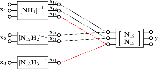
We need to construct a post-coding matrix 𝐍3×3𝐍superscript33\mathbf{N}\in\mathbb{R}^{3\times 3} at the relay, which zero-forces interference from user 3 in the sub-channel for bidirectional communication between users 1 and 2. Thus, let us choose the first two rows of 𝐍𝐍\mathbf{N} as a matrix spanning the null space of 𝐇3subscript𝐇3\mathbf{H}_{3}, denoted 𝐍122×3subscript𝐍12superscript23\mathbf{N}_{12}\in\mathbb{R}^{2\times 3}, i.e., 𝐍12𝐇3=𝟎subscript𝐍12subscript𝐇30\mathbf{N}_{12}\mathbf{H}_{3}=\mathbf{0}. Similarly, the last row of 𝐍𝐍\mathbf{N} is chosen as 𝐍131×3subscript𝐍13superscript13\mathbf{N}_{13}\in\mathbb{R}^{1\times 3} such that 𝐍13𝐇2=𝟎subscript𝐍13subscript𝐇20\mathbf{N}_{13}\mathbf{H}_{2}=\mathbf{0}. Thus, we obtain the post-coding matrix 𝐍=[𝐍12𝐍13]𝐍superscriptdelimited-[]superscriptsubscript𝐍12superscriptsubscript𝐍13\mathbf{N}=[\mathbf{N}_{12}^{\dagger}\ \mathbf{N}_{13}^{\dagger}]^{\dagger}. Then, after post-coding, the relay has the signal 𝐍𝐲rsubscript𝐍𝐲𝑟\mathbf{N}\mathbf{y}_{r} given by

[𝐍12𝐇1𝐍13𝐇1]𝐱1+[𝐍12𝐇20]𝐱2+[𝟎𝐍13𝐇3]𝐱3+𝐍𝐳r.matrixsubscript𝐍12subscript𝐇1subscript𝐍13subscript𝐇1subscript𝐱1matrixsubscript𝐍12subscript𝐇20subscript𝐱2matrix0subscript𝐍13subscript𝐇3subscript𝐱3subscript𝐍𝐳𝑟\displaystyle\begin{bmatrix}\mathbf{N}_{12}\mathbf{H}_{1}\\ \mathbf{N}_{13}\mathbf{H}_{1}\end{bmatrix}\mathbf{x}_{1}+\begin{bmatrix}\mathbf{N}_{12}\mathbf{H}_{2}\\ 0\end{bmatrix}\mathbf{x}_{2}+\begin{bmatrix}\mathbf{0}\\ \mathbf{N}_{13}\mathbf{H}_{3}\end{bmatrix}\mathbf{x}_{3}+\mathbf{N}\mathbf{z}_{r}.

Note that this establishes a 2×2222\times 2 MIMO sub-channel between user 2 and the first two components of 𝐍𝐲rsubscript𝐍𝐲𝑟\mathbf{N}\mathbf{y}_{r} without causing interference at the third component. Similarly for user 3, a SISO channel is established which does interfere with the first two components of 𝐍𝐲rsubscript𝐍𝐲𝑟\mathbf{N}\mathbf{y}_{r}. Now the task is to construct the pre-coding matrices such that the signal from user 1 to user 2, [u12,u12]superscriptsubscript𝑢12superscriptsubscript𝑢12[u_{12},\ u_{12}^{\prime}]^{\dagger}, is only seen at the first 2 components of 𝐍𝐲rsubscript𝐍𝐲𝑟\mathbf{N}\mathbf{y}_{r}, and the signal from user 1 to user 3, u13subscript𝑢13u_{13} is only seen at the last component of 𝐍𝐲rsubscript𝐍𝐲𝑟\mathbf{N}\mathbf{y}_{r}. This can be accomplished by choosing a pre-coding matrix at user 1 which diagonalizes the channel to 𝐍𝐲rsubscript𝐍𝐲𝑟\mathbf{N}\mathbf{y}_{r}. Users 1, 2, and 3 send

𝐱1=𝐕1[u12u12u13],𝐱2=𝐕2[u21u21],𝐱3=𝐕3u31,formulae-sequencesubscript𝐱1subscript𝐕1matrixsubscript𝑢12superscriptsubscript𝑢12subscript𝑢13formulae-sequencesubscript𝐱2subscript𝐕2matrixsubscript𝑢21superscriptsubscript𝑢21subscript𝐱3subscript𝐕3subscript𝑢31\displaystyle\mathbf{x}_{1}=\mathbf{V}_{1}\begin{bmatrix}u_{12}\\ u_{12}^{\prime}\\ u_{13}\end{bmatrix},\quad\mathbf{x}_{2}=\mathbf{V}_{2}\begin{bmatrix}u_{21}\\ u_{21}^{\prime}\end{bmatrix},\quad\mathbf{x}_{3}=\mathbf{V}_{3}u_{31},

where 𝐕1=[𝐍𝐇1]1subscript𝐕1superscriptdelimited-[]subscript𝐍𝐇11\mathbf{V}_{1}=[\mathbf{N}\mathbf{H}_{1}]^{-1}, 𝐕2=[𝐍12𝐇2]1subscript𝐕2superscriptdelimited-[]subscript𝐍12subscript𝐇21\mathbf{V}_{2}=[\mathbf{N}_{12}\mathbf{H}_{2}]^{-1}, and 𝐕3=[𝐍13𝐇3]1subscript𝐕3superscriptdelimited-[]subscript𝐍13subscript𝐇31\mathbf{V}_{3}=[\mathbf{N}_{13}\mathbf{H}_{3}]^{-1}. The resulting received signal at the relay is then

[w12w12w13]=𝐍𝐲r=[u12+u21u12+u21u13+u31]+𝐍𝐳r.matrixsubscript𝑤12superscriptsubscript𝑤12subscript𝑤13subscript𝐍𝐲𝑟matrixsubscript𝑢12subscript𝑢21superscriptsubscript𝑢12superscriptsubscript𝑢21subscript𝑢13subscript𝑢31subscript𝐍𝐳𝑟\displaystyle\begin{bmatrix}w_{12}\\ w_{12}^{\prime}\\ w_{13}\end{bmatrix}=\mathbf{N}\mathbf{y}_{r}=\begin{bmatrix}u_{12}+u_{21}\\ u_{12}^{\prime}+u_{21}^{\prime}\\ u_{13}+u_{31}\end{bmatrix}+\mathbf{N}\mathbf{z}_{r}.

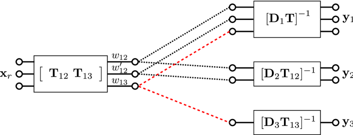
Now, we use a similar strategy in the downlink to obtain the channel structure shown in Fig. 4. The relay sends 𝐰=[𝐰12,𝐰13]𝐰superscriptsuperscriptsubscript𝐰12superscriptsubscript𝐰13\mathbf{w}=[\mathbf{w}_{12}^{\dagger},\ \mathbf{w}_{13}^{\dagger}]^{\dagger} where 𝐰12=[w12,w12]subscript𝐰12superscriptsubscript𝑤12superscriptsubscript𝑤12\mathbf{w}_{12}=[w_{12},w_{12}^{\prime}]^{\dagger}, and 𝐰13=w13subscript𝐰13subscript𝑤13\mathbf{w}_{13}=w_{13} along the columns of 𝐓=[𝐓12𝐓13]𝐓delimited-[]subscript𝐓12subscript𝐓13\mathbf{T}=[\mathbf{T}_{12}\ \mathbf{T}_{13}] where 𝐓12𝐃3=𝟎subscript𝐓12subscript𝐃30\mathbf{T}_{12}\mathbf{D}_{3}=\mathbf{0} and 𝐓13𝐃2=𝟎subscript𝐓13subscript𝐃20\mathbf{T}_{13}\mathbf{D}_{2}=\mathbf{0}. User 1 uses a post-coding matrix [𝐃1𝐓]1superscriptdelimited-[]subscript𝐃1𝐓1[\mathbf{D}_{1}\mathbf{T}]^{-1}, user 2 uses a post-coding matrix [𝐃2𝐓12]1superscriptdelimited-[]subscript𝐃2subscript𝐓121[\mathbf{D}_{2}\mathbf{T}_{12}]^{-1}, and user 3 uses a post-coding matrix [𝐃3𝐓13]1superscriptdelimited-[]subscript𝐃3subscript𝐓131[\mathbf{D}_{3}\mathbf{T}_{13}]^{-1}. As a result, the received signal at the three users become

[𝐃1𝐓]1𝐲1superscriptdelimited-[]subscript𝐃1𝐓1subscript𝐲1\displaystyle[\mathbf{D}_{1}\mathbf{T}]^{-1}\mathbf{y}_{1} =𝐰+[𝐃1𝐓]1𝐳1absent𝐰superscriptdelimited-[]subscript𝐃1𝐓1subscript𝐳1\displaystyle=\mathbf{w}+[\mathbf{D}_{1}\mathbf{T}]^{-1}\mathbf{z}_{1}
[𝐃2𝐓12]1𝐲2superscriptdelimited-[]subscript𝐃2subscript𝐓121subscript𝐲2\displaystyle[\mathbf{D}_{2}\mathbf{T}_{12}]^{-1}\mathbf{y}_{2} =𝐰12+[𝐃2𝐓12]1𝐳2absentsubscript𝐰12superscriptdelimited-[]subscript𝐃2subscript𝐓121subscript𝐳2\displaystyle=\mathbf{w}_{12}+[\mathbf{D}_{2}\mathbf{T}_{12}]^{-1}\mathbf{z}_{2}
[𝐃3𝐓13]1𝐲3superscriptdelimited-[]subscript𝐃3subscript𝐓131subscript𝐲3\displaystyle[\mathbf{D}_{3}\mathbf{T}_{13}]^{-1}\mathbf{y}_{3} =𝐰13+[𝐃3𝐓13]1𝐳3,absentsubscript𝐰13superscriptdelimited-[]subscript𝐃3subscript𝐓131subscript𝐳3\displaystyle=\mathbf{w}_{13}+[\mathbf{D}_{3}\mathbf{T}_{13}]^{-1}\mathbf{z}_{3},

from which each user can recover its desired signal.

Refer to caption
Figure 4: The downlink in a Y-channel with (M1,M2,M3,N)=(3,2,1,3)subscript𝑀1subscript𝑀2subscript𝑀3𝑁3213(M_{1},M_{2},M_{3},N)=(3,2,1,3) showing the pre-coding and post-coding matrices. 𝐓12subscript𝐓12\mathbf{T}_{12} and 𝐓13subscript𝐓13\mathbf{T}_{13} are orthogonal to 𝐃3subscript𝐃3\mathbf{D}_{3} and 𝐃2subscript𝐃2\mathbf{D}_{2}, respectively, 𝐓=[𝐓12,𝐓13]𝐓subscript𝐓12subscript𝐓13\mathbf{T}=[\mathbf{T}_{12},\ \mathbf{T}_{13}], and w12subscript𝑤12w_{12}, w12superscriptsubscript𝑤12w_{12}^{\prime}, and w13subscript𝑤13w_{13} represent noisy linear combinations of (x12,x21)subscript𝑥12subscript𝑥21(x_{12},x_{21}), (x12,x21)superscriptsubscript𝑥12superscriptsubscript𝑥21(x_{12}^{\prime},x_{21}^{\prime}), and (x13,x31)subscript𝑥13subscript𝑥31(x_{13},x_{31}), respectively.

References

  • [1] B. Rankov and A. Wittneben, “Spectral efficient signaling for half-duplex relay channels,” in Proc. of the Asilomar Conference on Signals, Systems, and Computers, Pacific Grove, CA, Nov. 2005.
  • [2] S. Kim, N. Devroye, P. Mitran, and V. Tarokh, “Comparisons of bi-directional relaying protocols,” in Proc. of the IEEE Sarnoff Symposium, Princeton, NJ, Apr. 2008.
  • [3] D. Gündüz, E. Tuncel, and J. Nayak, “Rate regions for the separated two-way relay channel,” in Proc. of the 46th Annual Allerton Conference on Communication, Control, and Computing, Urbana-Champaign, IL, Sep. 2008, pp. 1333 – 1340.
  • [4] W. Nam, S.-Y. Chung, and Y. H. Lee, “Capacity of the Gaussian two-way relay channel to within 1/2 bit,” IEEE Trans. on Info. Theory, vol. 56, no. 11, pp. 5488 – 5494, Nov. 2010.
  • [5] A. S. Avestimehr, A.Sezgin, and D. Tse, “Capacity of the two-way relay channel within a constant gap,” European Trans. in Telecommunications, vol. 21, no. 4, p. 363–374, 2010.
  • [6] T. J. Oechtering, C. Schnurr, I. Bjelakovic, and H. Boche, “Broadcast capacity region of two-phase bidirectional relaying,” IEEE Trans. on Info. Theory, vol. 54, no. 1, pp. 454–458, Jan. 2008.
  • [7] Y. Song, N. Devroye, H.-R. Shao, and C. Ngo, “Lattice coding for the two-way two-relay channel,” submitted to IEEE Trans. on Info. Theory, arXiv:1212.1198 [cs.IT], Dec. 2012.
  • [8] D. Gündüz, A. Yener, A. Goldsmith, and H. V. Poor, “The multi-way relay channel,” in Proc. of IEEE International Symposium on Info. Theory (ISIT), Seoul, South Korea, Jun. 2009.
  • [9] L. Ong, C. Kellett, and S. Johnson, “Capacity theorems for the AWGN multi-way relay channel,” in Proc. of IEEE International Symposium on Info. Theory (ISIT), 2010.
  • [10] A. Sezgin, A. S. Avestimehr, M. A. Khajehnejad, and B. Hassibi, “Divide-and-conquer: Approaching the capacity of the two-pair bidirectional Gaussian relay network,” IEEE Trans. on Info. Theory, vol. 58, no. 4, pp. 2434–2454, Apr. 2012.
  • [11] A. Sezgin, H. Boche, and A. S. Avestimehr, “Bidirectional multi-pair network with a MIMO relay: Beamforming strategies and lack of duality,” in Proc. of Allerton Conference, Monticello, IL, USA, 2010.
  • [12] N. Lee, J.-B. Lim, and J. Chun, “Degrees of freedom of the MIMO Y channel: Signal space alignment for network coding,” IEEE Trans. on Info. Theory, vol. 56, no. 7, pp. 3332–3342, Jul. 2010.
  • [13] A. Chaaban, A. Sezgin, and A. S. Avestimehr, “On the sum capacity of the Y-channel,” submitted to IEEE Trans. on Info. Theory, arXiv:1102.2787, 2012.
  • [14] S. A. Jafar, “Interference alignment: A new look at signal dimensions in a communication network,” Foundations and Trends in Communications and Information Theory, vol. 7, no. 1, pp. 1–136, 2012.
  • [15] T. Cover and J. Thomas, Elements of information theory (Second Edition).   John Wiley and Sons, Inc., 2006.