Demonstration of Motion Transduction Based on Parametrically Coupled Mechanical Resonators
Abstract
Universal sensing the motion of mechanical resonators with high precision and low back-action is of paramount importance in ultra-weak signal detection which plays a fundamental role in modern physics. Here we present a universal scheme that transfer mechanically the motion of the resonator not directly measurable to the one can be precisely measured using mechanical frequency conversion. Demonstration of the scheme at room temperature shows that both the motion imprecision and the back-action force are below the intrinsic level of the objective resonator, which agree well with our theoretical prediction. The scheme developed here provides an effective interface between an arbitrary mechanical resonator and a high quantum efficient displacement sensor, and is expected to find extensive applications in high-demanding mechanical-based force measurements.
pacs:
03.65.Ud, 03.65.Ta,76.70.Hb, 76.30.MiMechanical resonators have been used as sensitive detectors of weak force generated from small charge Cleland , single electron spin Rugar , the acceleration of a single gold atom Jensen , and quantilized magnetic flux Harris . Generally speaking, to reach a higher force sensitivity, a smaller mechanical resonator is needed. Mechanical resonators at nano- and subnano- scale based on carbon nanotube CNT , nanowire Nichol and multi- and single- layer graphene Bunch have recently been demonstrated as potentially suitable force sensors. However, scaling down the size of mechanical resonator makes the detection of its motion a big challenge.
Quantum mechanics tells us that the measurement of position brings about back-action to the mechanical object. The product of sensitivity and the back-action known as noise product (NP) are used to characterize the measurement process Clerk . Among the state-of-art displacement sensors, the one based on optical photon has been shown to have very high displacement sensitivity Arcizet ; Verlot as well as a controllable NP cooling ; Schliesser , where the typical size of the mechanical resonator is much larger than optical wavelength. Further reduction of the size of the resonator to sub-wavelength level results into the reduction in photon-mechanical coupling proportionally, and so a much stronger optical power is needed to offset the reduction, which could bring additional noise, such as heating effect, and would further limit the sensitivity Nichol . Non-optical methods have recently been developed to detect the motion of nano-mechanical resonator by using single-electron transistor Knobel ; LaHaye , quantum point contact Cleland1 ; Poggio , superconducting interferometer Etaki , microwave resonator Regal , and single electron spin Lukin . With further improvements, especially those based on optimizing resonator-detector geometry, not only high sensitivity, but also very low NP has been demonstrated cooling ; jacobs ; Teufel ; Schliesser . If the coupling between these remarkable but objects-dependent detectors with the motion of arbitrary mechanical resonators is realized efficiently, these schemes will have wide applications. However, the exploration of such an interface remains elusive. The solution is to realize an efficient motion transduction between arbitrary mechanical resonators. In contrast to the coupling to quantum mechanics objects via optical and microwave photons etc. Arcizet ; Verlot ; Regal ; Teufel ; Wei2006 , the coupling between mechanical objects via classical forces, such as electrostatic force Roukes1 ; Roukes2 , dielectric force Die1 ; Die2 and electrothermal force thermal , is more universal, in that it has no stringent limitations on size, geometry and material of the mechanical systems, and so provides a better choice for motion transduction.
Here we report a motion transduction scheme based on mechanical parametric coupling and its experimental demonstration. A transduction process with a displacement transduction imprecision of m and a back-action force less than N have been achieved at room temperature. Both the imprecision and the back-action force are lower than the intrinsic noise levels of the low frequency resonator being transferred, ensuring the transduction efficiency.
Our motion transduction device consists of two parametrically coupled mechanical resonators: a target resonator T, whose motion is being transduced, and a detector resonator D, whose response in terms of force is the destination of the transduction. The dynamics of the system can be described classically by the equations for the displacements and for resonators T and D, respectively, as follows:
| (1) |
Here , and are resonators T and D’s effective masses, spring constants, and intrinsic dissipation rates, respectively. is the pumping field to realize parametrical coupling between the two resonators with the coupling strength and the pumping frequency . is related to the resonators’ natural (angular) frequencies and quality factors by . The case of interest here is , with the frequency of pumping field satisfying the frequency conversion (denoted as FC hereafter) condition:
| (2) |
The motion excited on the resonator T is up-converted to the motion of resonator D for detection. FC has been studied in various physical system such as nonlinear optics and recently been realized in micro-mechanical system mixer . The noise level of the transduction process is characterized by two parameters, the transduction imprecision which is equivalent to the measurement imprecision if resonator D is taken as a force-based displacement sensor, and the back-action force . A calculation using the input-output theory (see Supplementary information for details) leads tonote
| (3) |
where , , and are the resonator D’s intrinsic thermal noise densities of displacement and force and the phonon number, respectively. At a temperature low enough, Eq. (3) leads to the quantum mechanical limit, as expected. A product similar to the second equality of Eq. (3) holds for resonator T. At high temperatures, , we obtain using Eq. (3) . Here and are resonator T’s intrinsic thermal noise densities of the displacement and force, respectively. This shows that a resonator D with higher frequency is the actually requirement for high transduction efficiency. For the case of weak force sensing, although the dissipation could set indirectly some constraints on the required effective coupling strength , we show that physical realization is feasible (see Supplementary information for details).
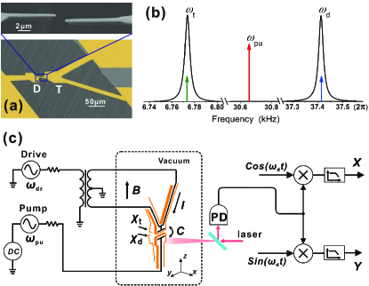
Our device to demonstrate the motion transduction and the measurement scheme is illustrated in Fig. 1. The device consists of two silicon mechanical resonators of thickness 1 m (Fig. 1(a)) which were made of SOI wafer by double-sided lithography and reactive ion etching; a nm/ nm of Au/Cr with Cr as an adhesion layer was evaporated onto the surface to generate a conductive path. The separation between the two resonator tips was about 1 m. Resonator T has two legs connected to external electrodes for the purpose of excitation of motion, so that in the presence of a static magnetic field, the Lorentz force on the small current generated by an a.c. drive voltage can excite the motion of Resonator T without disturbing Resonator D. By applying a time-dependent pumping voltage between the two resonators, there is an electrostatic force produced, which results in a effective pumping field in unit of N/m Rugar2 . Here is the effective capacity between the two resonators. In practice, is realized by a superposition of a d.c. voltage and an a.c. voltage of frequency satisfying Eq. (2). In this case, only the cross term of actually contributes to the FC process due to frequency constrains and the effective coupling strength is then (see Supplementary information for details).
The experiments were carried out at room temperature on the device suspended with springs in a vacuum chamber of pressure lower than mbar. The basic parameters of resonators were measured by fiber interferometer which consists of a 1550 nm-distributed-feedback laser diode using optical coupler, the laser was focused on the end of the resonator by a lens so that resonators T and D could be measured individually. The resonators T and D have natural resonance frequencies kHz and 37.41 kHz in absence of externally applied d.c. voltage, and quality factors and obtained by free ring down. The thermal noise spectral densities were measured optically. Then by applying the equipartition theorem Sidles2 , the effective spring constants were calculated to be N/m and N/m. The equation of motion for a damped harmonic oscillator leads to , from which the frequency-independent thermal force noise density can be calculated. From the measured , we obtained N/ and N/, and peak displacement noises m for resonator T and m for resonator D.
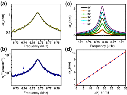
We first studied the frequency-domain behavior of resonator T under external excitation by monitoring the motion of resonator D. In order to do this, the reference frequency in demodulation (Fig. 1(c)) was fixed at , and the frequencies of both the drive and the a.c. pump voltages were swept under the constraint , and the amplitude of , and were set at V, V and V, respectively. The amplitude of resonator D was measured optically and plotted in Fig. 2(a) as a function of . It is important to ascertain that the dependence of actually gives the frequency-domain behavior of resonator T. This is confirmed by the fact that the curve in Fig. 2(a) coincides in both peak frequency and width with the thermal noise spectrum of resonator T plotted in Fig. 2(b), which was obtained from direct optical measurement. Measured results of for a series of applied a.c. pumping voltages are plotted in Fig. 2(c). The measured peak amplitude increases with the increase of proportionally, indicating that stronger pumping field can be used to produce stronger signal at resonator D for detection. However, deviation from this proportionality becomes apparent for strong enough pumping, as shown later in Fig. 3(a). Under a fixed amplitude of and while varying the amplitude of , the displacement of resonator D is shown in Fig. 2(d) to be proportional to the displacement of the target resonator T, as expected. These results show that the motion of resonator T is transduced to resonator D via the parametrical coupling process.
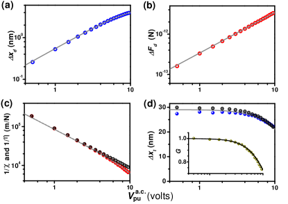
We further studied the dependence of the transduction process on the coupling strength when resonator T was under coherent resonant excitation and the FC was satisfied, i.e, and . The amplitudes of and were set at 100 V and 36 V, respectively. The amplitude was varied from 0.5 to 10 V. The results are plotted in Fig. 3. The displacement response of resonator D in Fig. 3(a) shows that under weak pumping the response increases linearly with a.c. pumping voltage, but as the pumping field increases further, nonlinear behavior appears, which fits well to the theoretical model and gives F/m2. Fig. 3(b) plots the corresponding force felt by resonator D which was calculated by using , where the gain factor was obtained from the optically measured displacements and . It shows the proportionality of to the a.c. pumping voltage, as expected. Fig. 3(c) plots the coupling strength derived from measured data by using and the effective transduction factor by using . It shows that equals under weak pumping, but is smaller than for strong pumping, as a result of the nonlinearity of the transduction process (see Supplementary information for details). The motion of resonator T measured by the transduction is compared to the one measured directly by optical method in Fig. 3(d). The agreement is reasonable well and becomes better when the pumping for parametric coupling becomes gradually stronger. The decrease of with the increase of pumping voltage clearly shows the decrease in the target resonator’s susceptibility to external driving force, by the extent described by the gain factor G plotted as subset of Fig. 3(d).
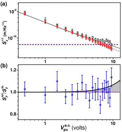
Having demonstrated the transduction of motion from resonators T to D, we investigated the noise of the transduction process. The amplitudes of and were set the same as those used to obtain Fig. 3. We first studied the transduction noise measured by resonator D. Fig. 4(a) shows the transduction imprecision derived from the optically measured data of , i.e., the force noise density of resonator D under pumping, using the definition and the total transduction noise . It shows that when V, the imprecision is m/, which is smaller than the intrinsic displacements noise of resonator T. The back-action of the transduction process was studied by measuring optically the force noises of resonator T when the pumping was off () and on (). The ratio is plotted in Fig. 4(b) together with theoretical curves. The back-action force noise calculated using for the measured data when V is only N, with a statistic error of N.
In conclusion, we have explored a method to realize motion transduction by the FC process using parametric coupling between two separate mechanical resonators, and then designed experiments to test the scheme. Both the transduction imprecision and the back-action force are substantially smaller than the intrinsic noise level of the resonator being transferred, and this demonstrates the efficiency of the motion transduction.
Now we discuss the application of the scheme to weak force sensing. Supposing that the motion to be detected is from an ultra-sensitive cantilever (resonator T) with frequency kHz, force sensitivity the order of N and thermal displacement noise the order of m , and the resonator with frequency about MHz and being monitored by a superconducting cavity at about 100 mK Teufel can be taken as resonator D, we can realize the motion transduction with back-action force much smaller than the force noise level of resonator T, while at the same time the motion transduction efficiency is maintained (see Supplementary information for more details). Combining the transduction scheme with feedback control on resonator D can further improve the transduction sensitivity and realize dynamical cooling of resonator T, which is out of the scope of this work.
We thank Fei Xue for help in setting up the experimental hardwares and Yiqun Wang from Suzhou Institute of Nano-Tech and Nano-Bionics for fabricating the mechanical resonators. This work was supported by the National Key Basic Research Program of China (Grant No. 2013CB921800), the National Natural Science Foundation of China (Grant Nos. 11227901, 91021005, 11274299, 11104262 and 10834005) and the ‘Strategic Priority Research Program (B)’ of the CAS (Grant No. XDB01030400).
References
- (1) A. N. Cleland and M. L. Roukes, Nature (London) 392, 160 (1998).
- (2) D. Rugar, R. Budakian, H. J. Mamin, and B. W. Chui, Nature (London) 430, 329 (2004).
- (3) K. Jensen, K. Kim, and A. Zettl, Nature Nanotech. 3, 533(2008).
- (4) A. C. Bleszynski-Jayich, W. E. Shanks, B. Peaudecerf, E. Ginossar, F. von Oppen, L. Glazman, and J. G. E. Harris, Science 326, 272 (2009).
- (5) A. Eichler, J. Moser, J. Chaste, M. Zdrojek, I. Wilson-Rae, and A. Bachtold, Nature Nanotech. 6, 339 (2011).
- (6) J. M. Nichol , E. R. Hemesath , L. J. Lauhon, and R. Budakian, Phys. Rev. B 85, 054414 (2012).
- (7) J. S. Bunch , A. M. van der Zande, S. S. Verbridge, I. W. Frank , D. M. Tanenbaum, J. M. Parpia, H. G. Craighead, and P. L. McEuen, Science 315 (5811), 490–493(2007).
- (8) A. A. Clerk, M. H. Devoret, S. M. Girvin, F. Marquardt, and R. J. Schoelkopf, Rev. Mod. Phys.82, 1155 (2010).
- (9) O. Arcizet, P.-F. Cohadon, T. Briant , M. Pinard , A. Heidmann, J. M. Mackowski, C. Michel, L. Pinard, O. Francais, and L. Rousseau, Phys. Rev. Lett. 97, 133601 (2006).
- (10) P. Verlot, A. Tavernarakis , T. Briant , P.-F. Cohadon, and A. Heidmann, Phys. Rev. Lett. 104, 133602 (2010).
- (11) A. Naik, O. Buu, M. D. LaHaye, A. D. Armour, A. A. Clerk, M. P. Blencowe, and K. C. Schwab, Nature (London) 443, 193 (2006).
- (12) A. Schliesser, O. Arcizet, R. Rivière, G. Anetsberger, and T. J. Kippenberg, Nature Phys.5, 509 (2009).
- (13) R. G. Knobel, and A. N. Cleland, Nature (London) 424, 291 (2003).
- (14) M. D. LaHaye , O. Buu, B. Camarota, and K. C. Schwab, Science 304, 74 (2004).
- (15) A. N. Cleland , J. S. Aldridge , D. C. Driscoll, and A. C. Gossard, Appl. Phys. Lett. 81, 1699 (2002).
- (16) M. Poggio, M. P. Jura , C. L. Degen , M. A. Topinka, H. J. Mamin , D. Goldhaber-Gordon, and D. Rugar, Nature Phys.4, 635 (2008).
- (17) S. Etaki, M. Poot, I. Mahboob , K. Onomitsu, H. Yamaguchi, and H. S. J. van der Zant, Nature Phys.4, 785 (2008).
- (18) C. A. Regal, J. D. Teufel, and K. W. Lehnert, Nature Phys. 4, 555 (2008).
- (19) S. Kolkowitz, A. C. B. Jayich, Q. P. Unterreithmeier, S. D. Bennett, P. Rabl, J. G. E. Harris, and M. D. Lukin, Science 335, 1603 (2012).
- (20) N. E. Flowers-Jacobs, D. R. Schmidt, and K. W. Lehnert, Phys. Rev. Lett. 98, 096804 (2007).
- (21) J. D. Teufel, T. Donner, M. A. Castellanos-Beltran , J. W. Harlow, and K. W. Lehnert, Nature Nanotech. 4, 820 (2009).
- (22) L. F. Wei, Y.-X. Liu, C. P. Sun, and F. Nori, Phys. Rev. Lett. 97, 237201 (2006).
- (23) R. B. Karabalin, M. C. Cross, and M. L. Roukes, Phys. Rev. B 79, 165309 (2009).
- (24) R. B. Karabalin, Ron Lifshitz, M. C. Cross , M. H. Matheny , S. C. Masmanidis, and M. L. Roukes, Phys. Rev. Lett. 106, 094102 (2011).
- (25) K. L. Turner, S. A. Miller, P. G. Hartwell, N. C. MacDonald, S. H. Strogatz, and S. G. Adams, Nature (London) 396, 149 (1998).
- (26) Q. P. Unterreithmeier , E. M. Weig, and J. P. Kotthaus, Nature (London) 458, 1001 (2009).
- (27) I. Bargatin , I. Kozinsky, and M. L. Roukes. Appl. Phys. Lett. 90, 093116 (2007).
- (28) I. Mahboob, K. Nishiguchi, H. Okamoto and H. Yamaguchi, Nature Phys.8, 387 (2012).
- (29) Should symmetrized noise spectrum densities were employed, should be replaced by , which is essentially the same, especially at high temperature (see Supplementary information for details).
- (30) J. A. Sidles, J. L. Garbini, and G. P. Drobny, Rev. Sci. Instrum.63, 3881 (1992).
- (31) D. Rugar, and P. Grütter, Phys. Rev. Lett. 67, 699 (1991).