Possible sorting mechanism for microparticles in an evanescent field
Abstract
Mie scattering theory is used to calculate radiation forces on a dielectric microsphere illuminated by evanescent waves, produced by laser light transmitted obliquely through a flat horizontal dielectric surface. The incident field is identified with the evanescent field, and both and polarizations are considered. Our investigation consists of three parts. First, after highlighting the basic formalism, we report results for the radiation force published in an earlier paper [J. Opt. Soc. Am. B 12, 2429 (1995)], correcting a few trivial calculational errors. Second - the main objective of our paper - is to show how the vertical (lifting) force on microspheres, typically via a proper adjustment of the laser frequency, can be used to separate spheres differing by a slight amount in their refractive index. This is caused by an oscillatory behavior in the force with respect to the nondimensional wave number in the surrounding medium. Fine-tuning the wave number , relative to the given refractive indices in the system, may lead to particle expulsion. The sorting mechanism turns out to be feasible when is about 18-20 or larger, which actually is in the region of practical interest. Finally, we investigate how variations in the angle of incidence for the laser beam influences the resulting radiation force.
pacs:
42.50.Wk, 42.25.-p, 03.50.De, 42.25.FxI Introduction
The guidance and controlled movement of microparticles in an evanescent field from a laser beam is of considerable theoretical and practical interest. Theoretically, it is a problem in classical electromagnetic wave theory. From a practical point of view, one would like to construct devices permitting an effective and non-destructive way of propelling and sorting microparticles, such as ordinary dielectric particles (e.g. latex spheres), and biological particles such as red blood cells and bacteria. Our basic setup is as sketched in Fig. 1 (similar to Ref. almaas95 ): a spherical particle of radius centered at the origin is situated in an evanescent field above a horizontal flat dielectric surface. The distance between the plane and the sphere center is called . The refractive indices, for simplicity assumed to be real, are in the lower substrate, in the medium surrounding the sphere, and in the sphere itself. A plane laser beam is incident from below at an angle of incidence , greater than the critical angle characterizing total reflection, determined by with . In experiments it turns out that, when the power of the incident laser beam is some hundreds of milliwatts, the particle is lifted slightly above the surface and is subsequently moved along the surface at a speed of a few micrometers per second. The most common substance for the surrounding medium 2 is water, with refractive index . In general, Mie wave theory is needed in order to describe this situation (cf., for instance, Ref. barton89 ), whereas when the nondimensional wave number exceeds about 80 we can make use of the geometrical optics approximation with sufficient accuracy.
It is probably correct to say that the development of this field began with the experiment of Kawata and Sugiura in 1992 kawata92 . Their experimental setup was as sketched in Fig. 1, and solid materials, polystyrene latex spheres and glass spheres, were used. A Mie theoretical description of the effect was given in Ref. almaas95 , implying the use of an evanescent field taken to cover the entire incidence region. Although a limiting factor of this method is that the electromagnetic boundary conditions at the plate () are not accounted for, it turned out that this simplified approach was able to reproduce the experimental observations to a high level of accuracy. Later on, several theoretical works have been published, especially in connection with the trapping of microparticles in the evanescent field of an optical waveguide with a step index profile jaising05 . An interesting variant is to consider hollow glass spheres in the evanescent field ahluwalia11 . The theory for absorbing spheres has also been given brevik03 . There are several other related papers, for instance Ref. bekshaev11 studying the internal energy circulation in light beams, and Ref. walz99 dealing with ray optics calculations for dielectric spheres in an evanescent field. The review paper dienerowitz08 is also useful, as are the dissertations of Løvhaugen lovhaugen12 and Jaising jaising04 .
The purpose of the present paper is twofold: A. We recalculate and correct some of the expressions for the longitudinal and vertical radiation force from Ref. almaas95 . A few calculation errors in the earlier formalism made this undertaking worthwhile. Since the formalism is rather complicated, and as the results are of apparent importance in experimental situations, care should be taken to get them correct. Moreover, comparison with similar calculations made recently by Bekshaev bekshaev12 makes this recalculation desirable. B. Our second purpose is to exploit the fact that, for reasonably large values of the nondimensional wave number, called , the vertical force on a microsphere in the evanescent field is an oscillating function of . For certain narrow -intervals the vertical force can even be repulsive. That means, it is in principle possible to adjust and other parameters such that microspheres of given size and given refractive index are expelled from the main flow of particles with different (and non-resonating) refractive indices propagating in the evanescent field above the surface. We also investigate the non-monotonic dependence of the force on the angle of incidence. The possibility of using this evanescent setup as a sorting device is the key theme of the present paper.
Let us consider more closely the electromagnetic force acting on a microsphere. Assuming a homogeneous interior, the force acts only in the sphere’s boundary layer. The volume force density is (cf., for instance, Refs. stratton41 or brevik79 )
| (1) |
This force should be expected to dominate at the lower end of the sphere where the evanescent field is strongest. At first sight this is somewhat surprising, as one would expect the vertical force to be attractive, thus pulling the sphere down, towards the surface. The situation is however more complicated, at least for the following three reasons: first, the fields in the interior are concentrated near the surface, as whispering-gallery modes. The field power in such modes are known to be quite large, of the order of hundreds of watts under usual circumstances (cf., for instance, Refs. rokshari05 ; brevik10 ). Hence, it is possible that circulating modes of this sort become totally reflected from the boundary at the upper part of the sphere, and their interference giving rise to an outward directed force. The effects of interference have been noticed before, for instance by Jaising and Hellesø jaising05 for evanescent fields near a wave guide.
Second, the influence from electric conductivity in the sphere may come into play. If the surface of the sphere were a perfect conductor, light rays from below would evidently bounce off the surface and give rise to a repulsive contribution to the force. We investigated this point in some detail in Ref. brevik03 , together with an analysis of absorptive effects. Our conclusion was that a layer of adsorbed film on the sphere’s surface, making it partly conducting, could be an appreciable factor in the observed repulsive force. Quantitative estimates for the impurity-induced conductivity are of course difficult.
Third, one must expect that there are thermophoretic forces acting (they are also called photophoretic forces). By heating one side of an object, a thermal gradient is established resulting in a movement away from the hotter region (in our case the maximum intensity region), towards colder environments. The thermal forces are known to be strong, up to about 1000 times stronger than radiation pressure. Although the relative strength of the thermophoretic force in the Kawata-Sugiura setup kawata92 is difficult to estimate, it seems very probable that the thermal force component is largely responsible for the observed lifting of the spheres from the surface. Based upon numerical results in the next section, we derive a lower threshold for the magnitude of the thermophoretic force in the Kawata-Sugiura experiment. Recent treatises on thermophoretic effects can be found in Refs. shvedov10 and esseling12 . We suggest that thermophoretic effects are after all the most important factor among the three mentioned.
Can this sorting method be used for biological materials? Probably not, although the situation is not entirely clear. For cells, the situation generally becomes more diffuse since the radii of such particles are varying. However, one possibility might be to create a sorting mechanism also in this case by taking into account the differences in the refractive index between healthy and sick (or dead) material. For living bacteria, many refractive indices are reasonably well known ross57 , and the refractive indices are known to be higher for dead cells than for living cells. This is related to an effect which is called dielectrophoresis. A cell death is typically marked by a sharp increase in electric conductivity, as some ions can more easily pass through newly opened pores in the cellular membrane. In the dielectrophoretic analysis, one sorts live cells from dead ones by arranging for electric field gradients in a narrow constriction of the cell-carrying fluid. The inhomogeneous field thus becomes capable of migrating cells with a conductivity-dependent velocity. Recent experimental and theoretical work along these lines has been presented by Patel et al. patel12 .
Consequently, we have to conclude that a sorting method based upon differences in refractive indices seems most appropriate in cases where the particle radii are exactly known, as is the case for monodispersive spheres also called Ugelstad spheres. For these situations, it should be possible to separate spheres that differ by a small amount in their refractive index. The main experimental challenge would be to tune the frequency with a high degree of accuracy.
In the next section we recapitulate for the sake of readability some main points of the Mie theory in the form given in Ref. almaas95 , and in Sec. III we present numerical results in the form of several figures. Thus Fig. 2 corrects some results from almaas95 , assuming (water), and . Both polarizations and are covered. A general property inferred from the figure panels is that the nondimensional vertical forces when depicted versus the nondimensional wave number are negative (attractive), and are stronger for polarization than for polarization. The longitudinal forces are positive in all cases thus driving the microparticles forward, as expected.
Figures 3-7 show calculated results pertaining to the proposed sorting method. In order for the setup to be practically usefule, one key property is that the contrasts between the refractive indices have to be reasonably large. To keep oversight over the parameter values, we assume henceforth for the most part that and have fixed values, and . Both of these values are quite standard for dielectrics. The most important remaining parameter is thus .
One may ask: is the sorting method useful for liquids? The answer seems to be no, as the requirement about contrast is not fulfilled. There are some liquids that are known to have low refractive index (for instance the liquid called fluorine refrigerant R-22 has ), but even in such a case the contrast turns out to be insufficient. The conclusion is that one has most likely to resort to the case of a gas as ambient medium 2. For gases, the refractive indices are very close to unity; even for the extreme case of benzene the value of is only 1.00176. So, in the following we assume that is equal to unity, or close to it. As the figures will show, if is adjusted accurately enough, it is in principle possible to expel selected microparticles from the main flow traveling in the evanescent field above a planar surface.
II Extracts of the basic formalism
Here, we present the basics of the formalism (for more details, cf. Refs. almaas95 , barton89 , and bekshaev12A ). Let and denote the fields incident on the sphere in medium 2. In the following, we shall only need the radial components and , and the nondimensional wave number of the incident field is
| (2) |
The radial part of the Helmholtz equation allows us to expand the fields as
| (3) |
| (4) |
where and are field amplitudes, related to each other via . Moreover is the nondimensional radius, and
| (5) |
with is the Riccati-Bessel function. The spherical harmonic is with , and being respectively the polar and the azimuthal angles, and the time factor has been omitted.
When and are known, the coefficients and can be found as
| (6) |
| (7) |
with . Here the integration is taken over the whole spherical surface (in principle, the surface has an arbitrary radius set equal to in Ref. almaas95 , but we simplify the formalism by putting ).
We now identify the incident field with the evanescent field. Note that at this point, the presence of the substrate between media 1 and 2 is ignored; we let the mathematical expression for the evanescent field be extended to all negative values for the vertical coordinate . Let the origin be placed in the center of the sphere, which again lies at a height above the substrate. Let and denote the transmission coefficients for the field lying respectively in the plane of incidence ( polarization) and normal to it ( polarization),
| (8) |
| (9) |
Here is the angle of incidence in medium 1, and . With the abbreviations
| (10) |
we can then express the radial component of the incident field as
| (11) |
Together with an analogous expression for the magnetic field we can now calculate the coefficients and from Eqs. (6) and (7). We do not go into further detail here, but mention the following useful relations between the and polarizations,
| (12) |
| (13) |
In Ref. almaas95 we expressed and in terms of three integral quantities called , and . Here, the expression (46) for should have been multiplied with a factor 2, as well as the expression (49) for . Combined with some minor errors in the numerical code, a complete recalculation is desirable. We give the correct results in the next section.
III Calculated results, and discussion
Following the notation of Ref. almaas95 , we let denote the vertical and the horizontal force on the sphere. Their nondimensional counterparts are defined as
| (14) |
Figure 2, panels (a)-(d), replace figures 4-7 in our earlier article almaas95 . In contrast to the original article, where the nondimensional wave number was moderate, we have now been able to explore a much larger range of . We may now clearly see the oscillatory behavior which is typical for large , even for this choice of refractive index in medium 2, (panels (c) and (d)). Our definition for the polarizations and are as usual: polarization is when the field component in the substrate (medium 1) lies in the plane of incidence, whereas polarization is when the corresponding component is orthogonal to this plane.
From the panels in Fig. 2 it is seen, as mentioned above, that the absolute magnitude of the vertical force is biggest for the case of polarization. The same is true for the horizontal force . Of main interest here is evidently . This force is negative, as expected in this range of . It means that the radiation force seeks to pull the sphere down towards the surface. The force pushes the sphere forward, as mentioned. Typical horizontal velocities in the Kawata-Sugiura experiment, with water surroundings (medium 2), were in the region m/s. Note that the figures refer to the case where the sphere rests upon the surface, i.e., . The differences between panels (a)-(d) and the figures 4-7 in Ref. almaas95 are seen to be rather significant.
As a by-product of these figures, we can use them to estimate the lower threshold for the lifting force observed in the Kawata-Sugiura experiment kawata92 . According to these authors, ”the particle is forced to float from the substrate surface and to slide along the surface”. That means, there must be a lifting force which we shall call , attributed to thermophoresis in the previous section, strong enough to overcome gravity together with the radiation force. It must thus satisfy the inequality
| (15) |
It is instructive to consider a concrete example (cf. also Ref. brevik03 ). Let the incident laser beam power in vacuum be mW, distributed over a circular cross-sectional area of diameter 10 m. Then the Poynting vector becomes MW/m2=19.0 W/m2. Taking the radius of the sphere to be m, we calculate pN. If the density of the sphere is 2.4 g/cm3 (glass), the weight of it becomes 0.10 pN. Assuming Nd:YAG laser light with fundamental wavelength 1.06 m in vacuum, the wavelength in the surrounding medium 2 (assumed to be water with ) becomes m, giving . From Fig. 2(a) we read off , in the case of polarization. From Eq. (15) we thus get
| (16) |
The sphere’s weight, and the vertical radiation force, are thus in this case comparable.
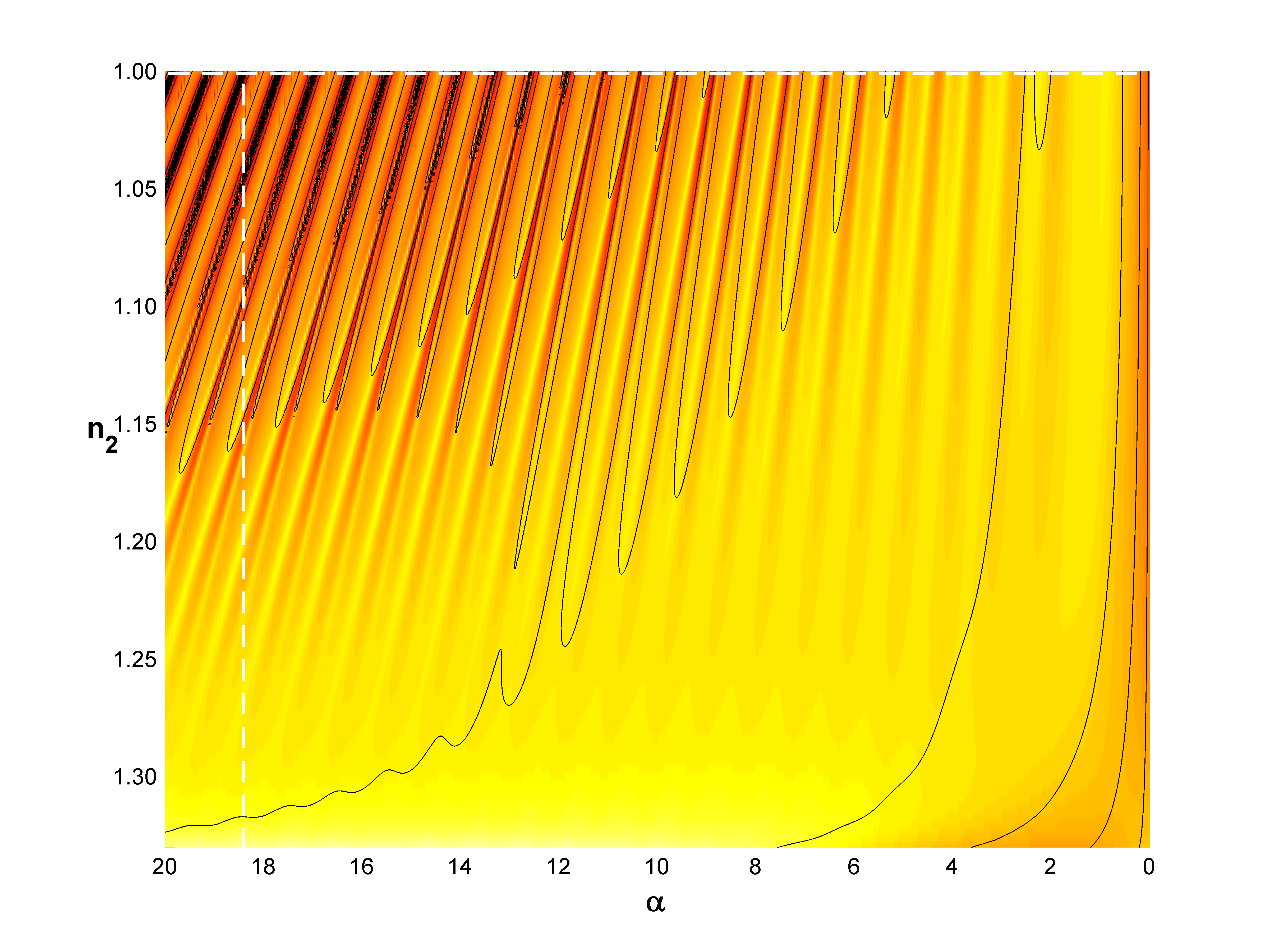
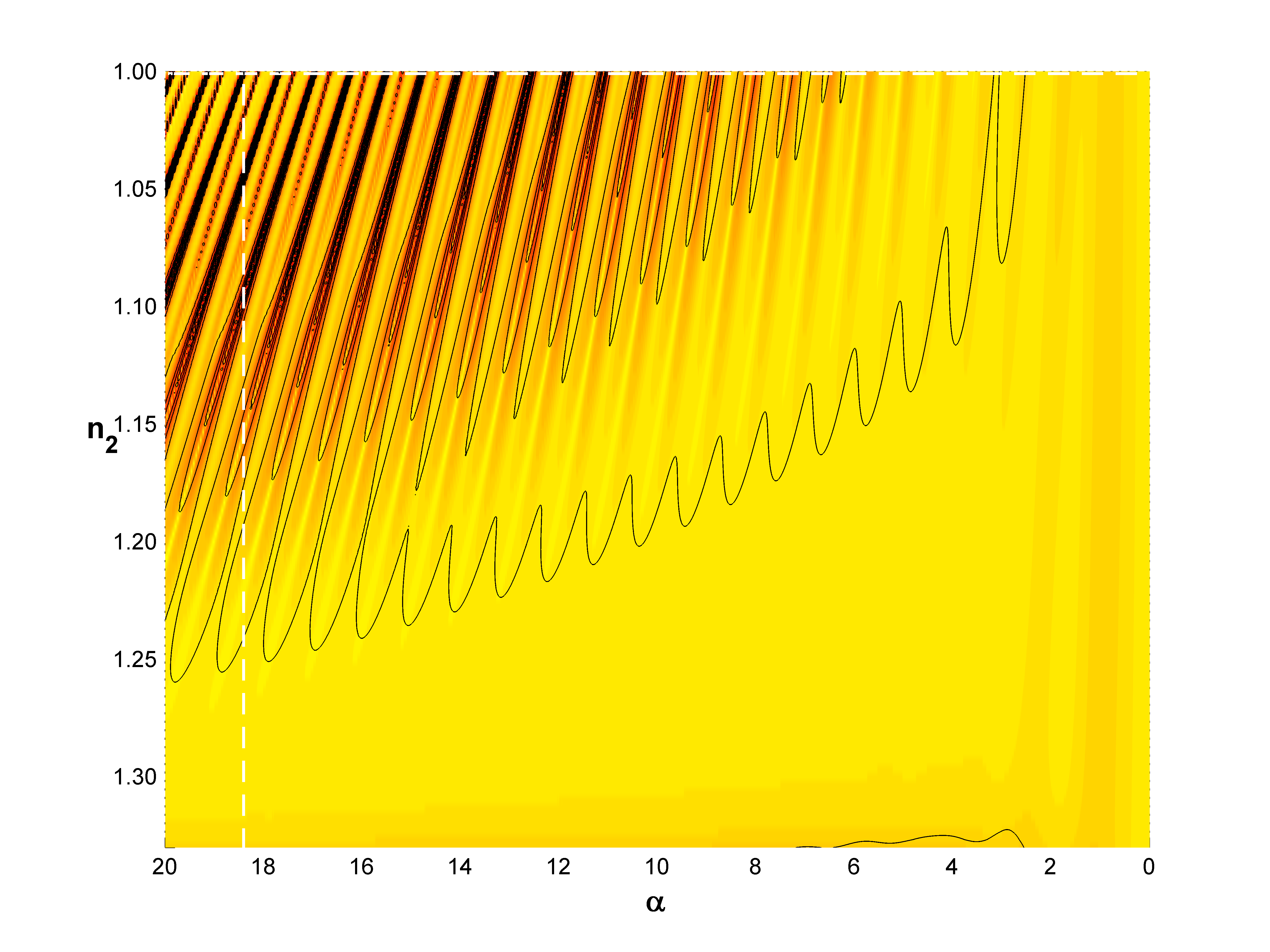
Figures 3-7 present our new results. Figure 3 is probably the one of main interest, as for a reasonable range of parameters it shows how the vertical force may expel selected microparticles from the main flow in the evanescent field above the planar surface. This requires, of course, a positive value of . Panel 3(b) corresponds to (gas). If is about 18 ( is about 3), which is a reasonable value for microparticles, we see that can reach a large value of about 5. This should be quite sufficient to give the selected particles a significant outward kick. From panel 3(c) it is seen that also for a larger value of (around 1.05), there is the possibility to obtain a significant outward force. Here, we have chosen the fixed wave number value , since it corresponds to a local force maximum (see panel (b)).
Singular behaviors of the same kind are also found for the horizontal force , as shown in Fig. 4. This is as one should expect. The horizontal force is however of secondary importance in the present problem. In addition to treating as the only adjustable parameter, it is of interest to investigate how different values of the refractive index in the sphere influence the force. This is illustrated in Fig. 5, assuming gas surroundings () and the fixed nondimensional wave number . We observe the presence of a sudden switch in the sign of when is slightly less than 1.50.
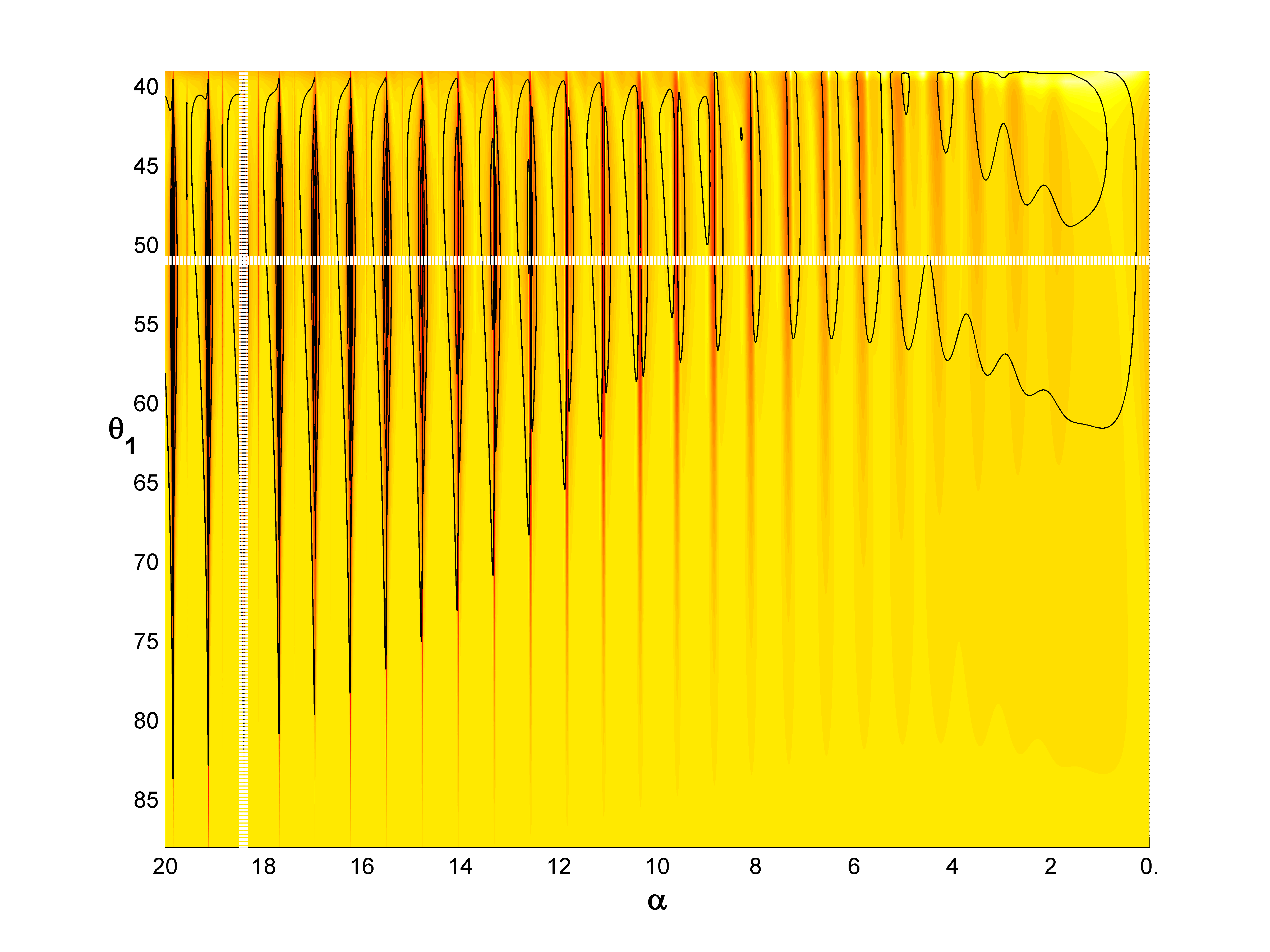
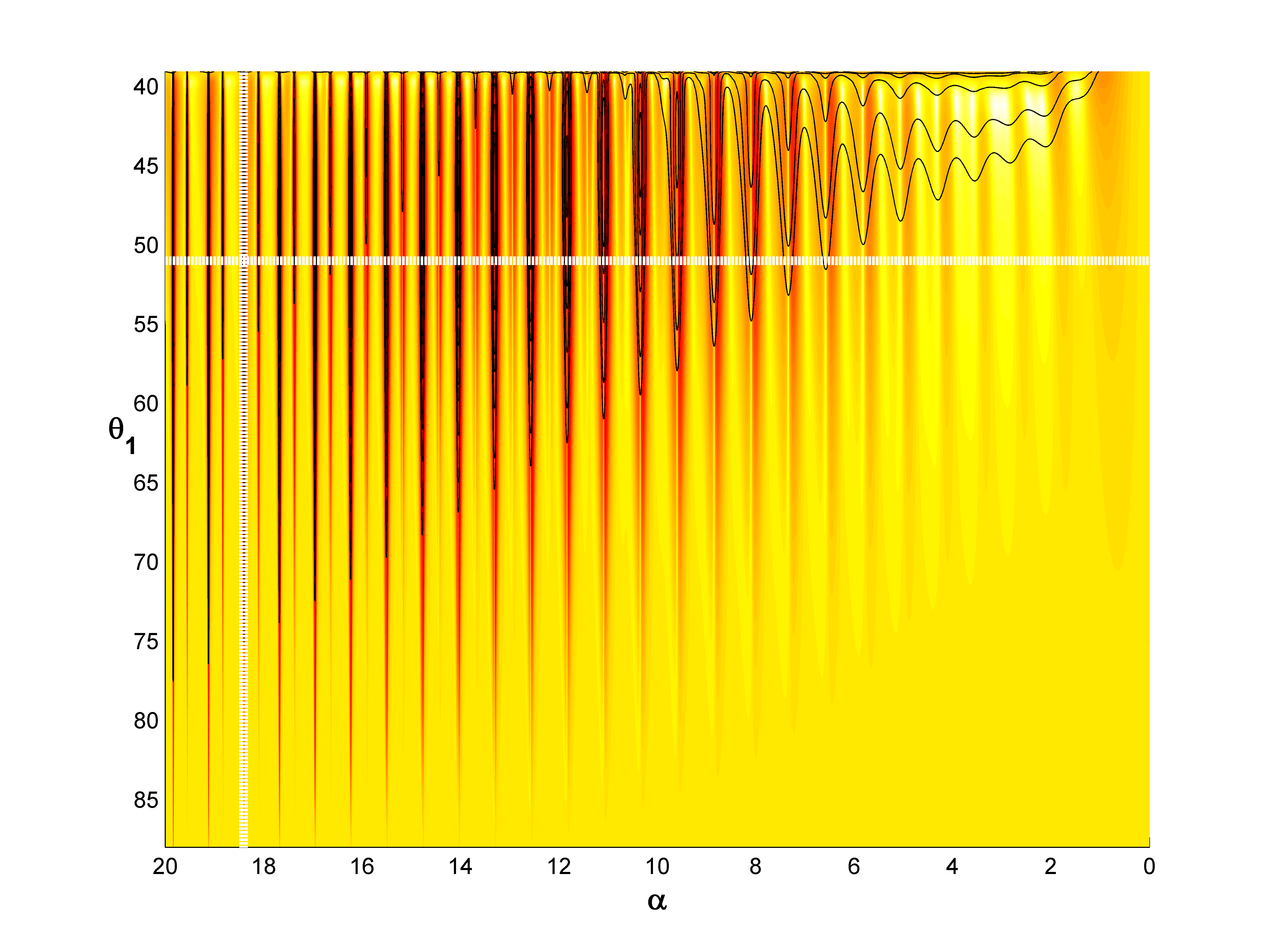
Finally, we have calculated the effect of using different values of the angle of incidence . Panel 6(a) shows how the vertical force varies versus values of the parameter set . Panel 6(b) demonstrates the sharp peaks versus when is kept fixed (), and panel 6(c) shows how the vertical force varies with when is kept constant (18.406). Figure 7 shows analogous results for the horizontal force .
To conclude: our theoretical investigations indicate that a sorting mechanism for selected microparticles in the evanescent field may under certain conditions be feasible. To investigate whether the method is useful in a practical application, one has to proceed to experimental tests.
Acknowledgments We thank Olav Gaute Hellesø and Pål Løvhaugen in Tromsø, and Aleksandr Bekshaev in Odessa, for valuable discussions and correspondence.
References
- (1) E. Almaas and I. Brevik, J. Opt. Soc. Am. B 12, 2429 (1995).
- (2) J. P. Barton, D. R. Alexander, and S. A. Schaub, J. Appl. Phys. 66, 4594 (1989).
- (3) S. Kawata and T. Sugiura, Opt. Lett. 17, 772 (1992).
- (4) H. Y. Jaising and O. G. Hellesø, Opt. Communications 246, 373 (2005).
- (5) B. P. S. Ahluwalia, P. Løvhaugen, and O. G. Hellesø, Opt. Lett. 36, 3347 (2011).
- (6) I. Brevik, T. A. Sivertsen, and E. Almaas, J. Opt. Soc. Am. B 20, 1739 (2003).
- (7) A. Ya. Bekshaev, K. Bliokh, and M. Soshkin, J. Opt. 13, 053001 (2011).
- (8) J. Y. Walz, Appl. Opt. 38, 5319 (1999).
- (9) M. Dienerowitz, M. Mazilu, and K. Dholakia, J. Nanophotonics 2, 021875 (2008).
- (10) P. Løvhaugen, PhD Dissertation, Department of Physics and Technology, University of Tromsø, Norway, 2012.
- (11) H. Y. Jaising, PhD Dissertation, Department of Physics, University of Tromsø, Norway, 2004.
- (12) A. Ya. Bekshaev, personal communication.
- (13) J. A. Stratton, Electromagnetic Theory (McGraw-Hill, New York, 1941), p. 140.
- (14) I. Brevik, Physics Reports 52, 133 (1979)
- (15) H. Rokshari, T. J. Kippenberg, T. Carmon, and K. J. Vahala, Opt. Express 13, 5293 (2005).
- (16) I. Brevik and S. Å. Ellingsen, Phys. Rev. A 81, 063830 (2010).
- (17) V. G. Shvedov et al., Phys. Rev. Lett. 105, 118103 (2010). See also V. G. Shvedov et al., Optonics & Photonics News, December 2012, p. 49.
- (18) M. Esseling, P. Rose, C. Alpmann and C. Denz, Appl. Phys. Lett. 101, 131115 (2012).
- (19) K. F. A. Ross, Quart. J. Microscopical Science 98, 435 (1957).
- (20) S. Patel et al., Biomicrofluidics 6, 034102 (2012). See also Physics Today, 65, September 2012, p. 19.
- (21) A. Ya. Bekshaev, O. V. Angelsky, S. G. Hanson, and C. Yu. Zenkova, Phys. Rev. A 86, 023847 (2012).


