Present address: ]Centro Brasileiro de Pesquisas Físicas, 22290-180, Rio de Janeiro, RJ, Brazil
Effect of perpendicular uniaxial anisotropy on the annihilation fields of magnetic vortices
Abstract
The magnetic vortex structure, that is present in several nanoscopic systems, is stable and can be manipulated through the application of a magnetic field or a spin polarized current. The size and shape of the core are strongly affected by the anisotropy, however, its role on the core behavior has not yet been clarified. In the present work we investigate the influence of a perpendicular anisotropy on the annihilation and shape of magnetic vortex cores in permalloy disks. We have used both micromagnetic simulations with the OOMMF code, and an analytical model that assumes that the shape of the core does not change during the hysteresis cycle, known as the rigid core model, to calculate the annihilation fields. In both cases we found that the annihilation fields decrease with increasing perpendicular anisotropy for almost all the structures investigated. The simulations show that for increasing anisotropy or dot thickness, or both, the vortex core profile changes its shape, becoming elongated. For every dot thickness, this change does not depend on the dot radius, but on the relative distance of the core from the center of the dot.
I Introduction
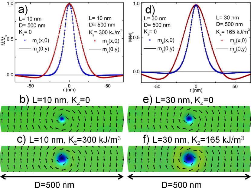
Among the nano- and mesoscopic magnetic structures that have attracted the attention of researchers in recent years stand out those that exhibit a vortex, since this state presents both interesting physical properties and a high potential for applications.Guimarães (2009); Chien et al. (2007); Guslienko (2008); Bohlens et al. (2008); Ruotolo et al. (2009); Jung et al. (2012) Magnetic vortex states in nanodots are characterized by in-plane magnetic moments curling around a core which has magnetization pointing out-of-plane. Two main features are defined in a vortex, the circulation, i.e., the sense of the magnetization curling, being for clockwise (counterclockwise) rotation direction, and the polarity defined by the direction of the core magnetization denoted by for upward (downward) direction. The core profile (the component of the unit magnetization) of a vortex in equilibrium is cylindrically symmetric, usually approximated by a Gaussian curve surrounded by a small dip (see Fig. 1).Guimarães (2009); Bode et al. (2008)
A vortex configuration is the ground state of different nanodots with regular shape such as ellipses, squares, spheres, caps and disks, with lateral dimensions ranging from one hundred nanometers to a few microns, with some tens of nanometers thickness.Landeros et al. (2005); Altbir et al. (2007); Zhang et al. (2008); Metlov and Lee (2008); Soares et al. (2008); Chung et al. (2010); Novais et al. (2011) While an external in-plane magnetic field that increases continuously from zero is applied to a disk exhibiting a magnetic vortex, its core will be displaced perpendicularly to the field direction, until its center reaches the disk edge. The field corresponding to this limiting situation, i.e., a field that expels the vortex core, is known as the annihilation field. A further field increase will expel the vortex from the disk, and the saturated state will eventually be reached. On the other hand, when starting from a fully saturated state, by decreasing the field to a certain critical value (commonly referred in the literature as the nucleation field) the vortex will again be formed. The knowledge and control of the magnitude of these fields is a key issue for several applications considering the manipulation of magnetic vortices, such as non-volatile magnetic memory devices, or high-resolution magnetic field sensors. Rahm et al. (2003); Kim et al. (2008); Garcia et al. (2010)
The vortex-core nucleation and annihilation processes have been discussed by several authors Schneider et al. (2000); Fernandez and Cerjan (2000); Guslienko and Metlov (2001); Guslienko et al. (2001); Mejia-Lopez et al. (2006); Mejía-López et al. (2010) and, in particular, the influence of extrinsic properties on the annihilation field has been taken into account. Wu et al. Wu et al. (2008) investigated the role of geometrical asymmetries, finding that the annihilation of the vortex depends strongly on the asymmetry. The effect of the shape asymmetry has also been studied by Dumas et al. Dumas et al. (2009), by measuring the angular dependence of the annihilation field. Mihajlović et al. Mihajlović et al. (2010) have shown that temperature also affects the reversal mechanism and the vortex annihilation field, while experiments by Davis et al. Davis et al. (2010) suggest that the nucleation and annihilation fields depend on the magnetic field sweep rate.
This problem was also examined from the theoretical point of view, within the framework proposed by Guslienko et al.Guslienko and Metlov (2001) This model approximates the core as a magnetization distribution whose profile does not change during the reversal process.
Some important properties of the vortices, such as the core size and some dynamic features, can be tailored introducing a uniaxial perpendicular magnetic anisotropy, as has been recently shownGarcia et al. (2010); Machado et al. (2008) In this case, as the perpendicular anisotropy increases, important deviations from the vortex core profile and from the canonical magnetic vortex configuration result. Beyond a critical value of the anisotropy (), it is no longer observed a vortex, with the formation of a skyrmion (e.g., Fert et al.Fert et al. (2013)), a structure that was found in experiments with BFeCoSiYu et al. (2010) and, more relevant to the present study, was also apparent in experiments with Co/Pt disksGarcia et al. (2010) and simulations.Garcia et al. (2010); Novais et al. (2011)
Vortex core deformations, even under the action of a magnetic field, have not been so far systematically analyzed.
The aim of this paper is to get a better understanding of the vortex annihilation process in magnetic dots. For this, we have compared the description using the rigid vortex model with results obtained by micromagnetic simulations. In order to explore the effect of the perpendicular anisotropy on the vortex core properties, and concomitantly, verify the limits of validity of the rigid vortex model, we have introduced an anisotropic term in both the theory and simulations. We also characterized the vortex core deformations that are present in some simulations.
The paper is organized as follows: after the Introduction we describe how we perform our micromagnetic simulations that lead us to study the annihilation fields extracted from the hysteresis curves of disks with various sizes (Sec. II). Analytical calculations are presented in Sec. III, with the inclusion of anisotropy terms into the rigid vortex model. The results are contained in Sec. IV, and finally, in Sec. V we summarize and draw conclusions.
II Numerical Simulations
We investigated the hysteresis loops of individual magnetic nanodots defined by their thickness varying between 10 and 30 nm, and diameters from 100 to 1000 nm, while the uniaxial perpendicular anisotropy ranges from 0 to 300 kJ/m3. This study was conducted through micromagnetic simulations Kim (2010); Novais et al. (2011) using the OOMMF code.Donahue and Porter (1999) We used a stiffness constant J/m and a saturation magnetization A/m, the standard values used for bulk permalloy, taking a cell size of nm3. The maximum anisotropies used in this work that keep the vortex structure are kJ/m3 for the thicknesses nm, respectively.
For larger anisotropies, a skyrmion structure is observed, and perpendicular magnetization appears on the rim of the disk. For this reason, in all our calculations the anisotropy constant value was chosen such that the magnetic configuration at zero external applied field is a vortex configuration, as shown in Fig. 1.
In our simulations we developed a systematic study of the annihilation field that is determined from the maximum of the derivative in the increasing magnetization branch of the hysteresis loop, which corresponds to the expulsion of the vortex core. All hysteresis curves were obtained starting from the unperturbed configuration of the disks (with the vortex core at the center), increasing the field from , in steps of mT, leading us to obtain the annihilation field, and finally reaching the magnetic saturation. In some simulations we observed a deformation of the vortex core. In order to characterize it we define
| (1) |
where and are the sizes of the vortex core along the and axes, respectively. As shown in Fig. 1, two orthogonal sections (x and y directions) of the profiles of the vortex core passing through the core center (maximum of ) were made. The dimensions of the core along the and directions were obtained by the full widths at half maximum of the repective profile fit, using a pseudo-Voigt function.
III Analytical Model
To obtain analytical expressions for the annihilation field in the magnetic nanodots we started with a model proposed by Guslienko et al. Guslienko and Metlov (2001); Guslienko et al. (2001) to investigate the vortex behavior in submicron dots. These authors considered a ferromagnetic dot with a height and a radius that presents a vortex state with a distribution of the unit magnetization in cylindrical coordinates given by , whereGuslienko et al. (2001)
| (2) |
Here is the radius of the core. If we consider magnetostatic, exchange, and Zeeman contributions to the energy, the normalized dimensionless vortex annihilation field in the rigid core model proposed by Guslienko et al.Guslienko et al. (2001) is written as
| (3) |
where , is the exchange length and is given by
| (4) |
III.1 Introducing a Perpendicular Uniaxial Anisotropy
While the model proposed by Guslienko et al. Guslienko and Metlov (2001); Guslienko et al. (2001) contains no anisotropy, in our calculations we include a uniaxial anisotropy along the axis and focus on its effect on the annihilation field. We start calculating the anisotropy energy contribution of the system that is given by
| (5) |
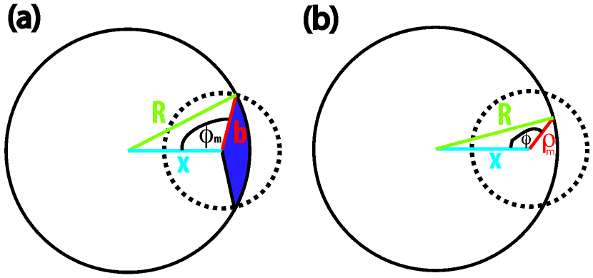
where is the anisotropy constant and is the easy axis. From this expression, the contribution to the energy due to the anisotropy comes only from the core region inside the dot. From Fig. 2 we obtain
| (6) |
and
| (7) |
Using these expressions we can write Eq. 5 as
| (8) |
| (9) |
In this expression and represents the contributions to the anisotropy energy shown in the dark regions in Fig. 2a
| (10) |
When or , can be approximated to zero at first order of . However, in our calculations we considered it explicitly. If the anisotropy energy is normalized to , that is, , and using , and , we obtain
| (11) |
where . We proceed by minimizing the magnetic anisotropy energy with respect to and evaluating in the equilibrium displacement where the vortex center reaches the dot perimeter. In other words, differentiating Eq. 11 with respect to and taking the limit , we obtain the value of the contribution of the anisotropy to the annihilation field
| (12) |
In this way, and adding this expression to the annihilation field given by Eq. 3, we obtain the annihilation field for a nanodot with perpendicular anisotropy
| (13) |
IV Results and Discussion
Our analyses for the annihilation field are based on a theoretical approach and on micromagnetic simulations. From both approaches we have obtained the dependence with the perpendicular anisotropy of the annihilation fields; from the simulations the core diameters were also obtained. We present below the results for the two cases: IV.1 annihilation field, and IV.2 evolution of the magnetic core shape. We have observed that the analytical calculations result in larger annihilation fields as compared with the numerical simulations, however, there is a qualitative agreement between the results from both models. A qualitative agreement between theretical results and measured annihilation fields was previously reported.Novosad et al. (2001)
IV.1 Annihilation fields
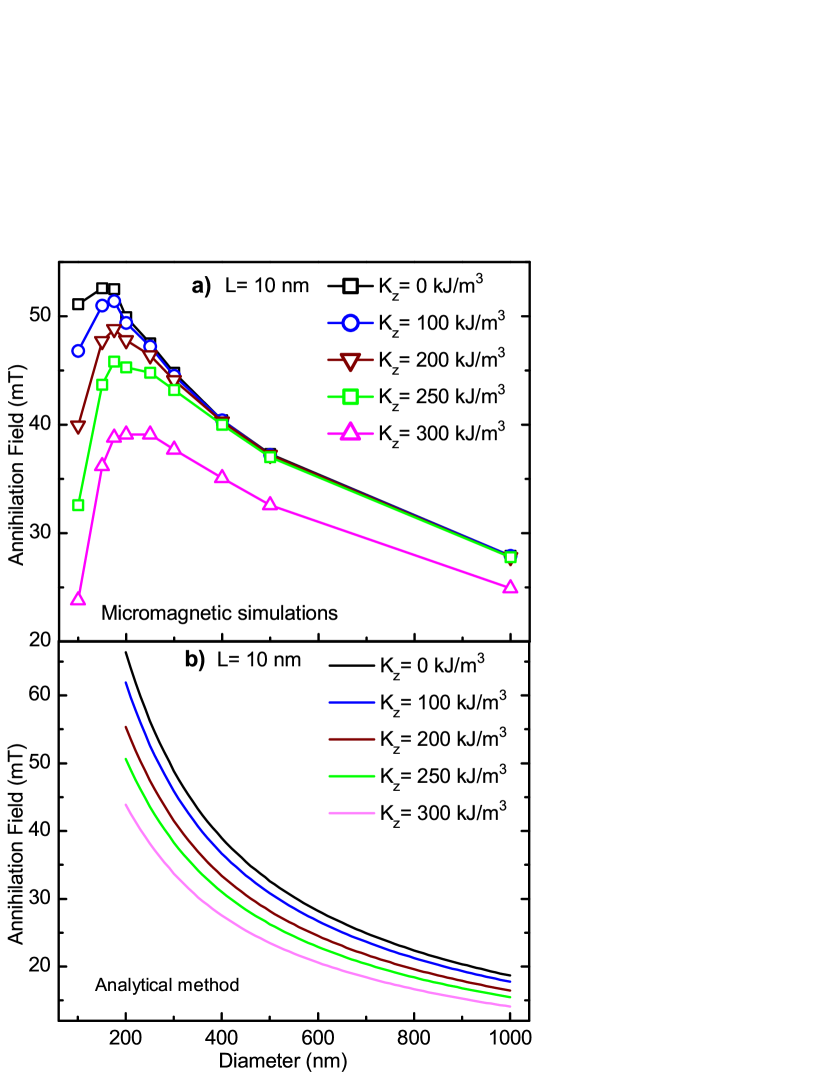
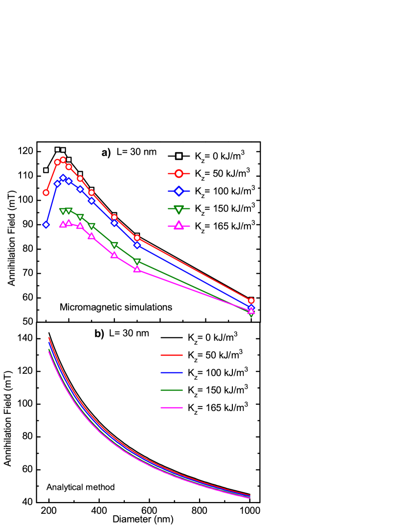
The values of the annihilation fields as a function of disk diameter, for different anisotropies , obtained from both methods are given in Figs. 3, 4 and 5 for nm, respectively.
The two sets of results agree in the fact that, as the diameters of the disks increase, the values become less dependent on the anisotropy (Figs. 3, 4 and 5).
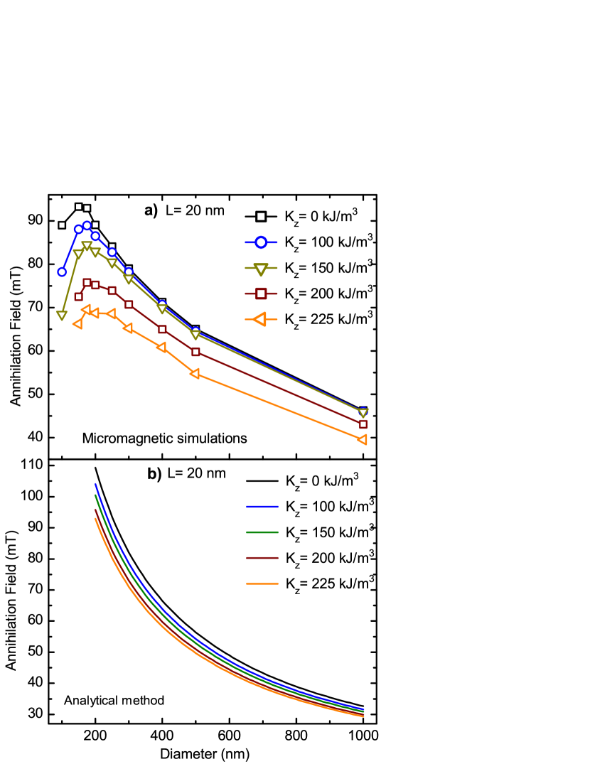
Increasing the anisotropy, which results in larger core sizes, one is led to lower annihilation fields.
For small diameters, the effect of the anisotropy is more noticeable than for the large disks, both in the theory and simulations. In the simulations, the sensitivity of the annihilation field to changes in anisotropy increases with the value of .
The disagreement between the two methods can be related to a deformation of the core observed in the micromagnetic simulations.
IV.2 Evolution of the magnetic core shape
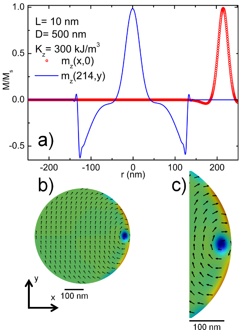
In the search of the effect that gives rise to the disagreement between the values of derived by analytical method and by numerical calculation, as we mentioned above, we considered the possibility that this effect would also cause a deformation of the vortex cores. Our micromagnetic simulations show that this deformation is in fact present, as shown in Figs. 6 and 7. Of course, the rigid vortex model breaks down in the cases where important deformations of the vortex core are observed.
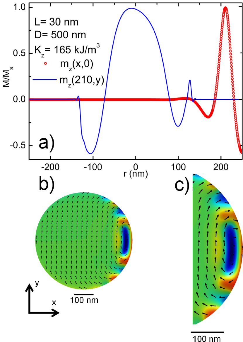
We have therefore analyzed the evolution of the shape of the magnetic vortex core as it moves towards the edge of the disks, under the influence of an applied magnetic field; the effect of varying the value of a perpendicular anisotropy was also investigated. The simulation results show a gradual deformation of the vortex cores, that can be quantified; the vortex cores change from a circular shape to a nearly elliptical (“banana-like”) shape. Figs. 6 and 7 show images of the vortex core and the core profile for nm and nm; the change in shape of the vortex core is very clear.
Comparing Fig. 1 and Figs. 6 and 7, we observe that the vortex core deformation increases as the core moves away from the center. The deformation is zero (i.e., the core is circular) for and maximum when the vortex core is on the edge of the disk, in the instant immediately before the vortex annihilation.
To clarify this point we have drawn the magnetization profile of the core for fields close to the annihilation field for dots of and 30 nm, as shown in Figs. 6a and 7a, respectively. The dark region (blue online) in these figures represents the core region. The profile of the vortex core at the center of the disk is shown in Fig. 1. The Figs. 1a, 1b and 1c show the effect of the anisotropy on a dot of diameter nm with nm, and Figs. 1d, 1e and 1f for diameter nm, with nm.
For nm the core keeps a nearly circular shape, the core deformation reaches about 10 % for zero anisotropy (), and for kJ/m3 the deformation is around 30%. Comparing Figs. 1a, 1b and 1c with Fig. 6, it is evident the vortex core deformation in the latter, due to an increase of its size along the axis and the depth of the magnetization dip.
However, for nm, the smallest core deformation is 30%, that corresponds to anisotropy , and a larger core deformation is observed for kJ/m3, of about 100%. Therefore, the core loses its circular shape for large anisotropy constant values , leading to a core of roughly elliptical section that is not well described by the rigid vortex model. This is shown in Figs. 6 and 7, where it is more evident the deformation of the vortex core, as well as the variation in the magnetization dip. It is important to note that a higher anisotropy constant for nm will result in a magnetic configuration that is not a vortex, as observed above. Therefore kJ/m3 is the largest value that can be considered in order to obtain a vortex state.
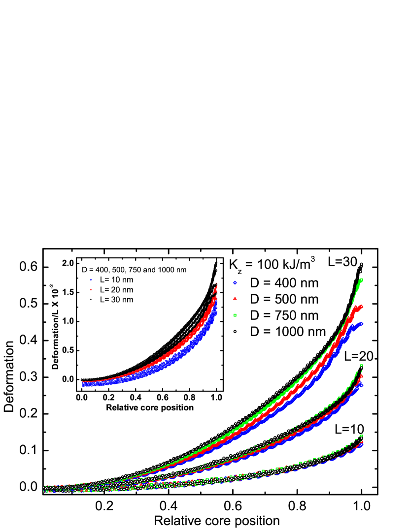
We observe that the core deformation is not present for , as shown in Fig. 1. However, as the field begins to increase, the process of deformation of the core sets in, as can be seen in Figs. 8 and 9, plotted from values obtained using Eq. (1); they are shown as a function of relative core positions (), defined as the ratio of the distance of the core center from the center of the disk () divided by the disk radius ().
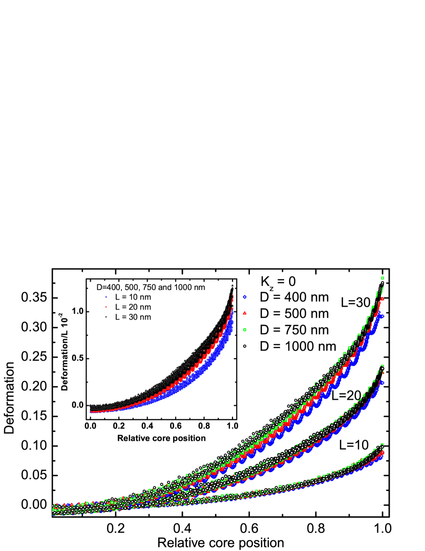
Figures 8 and 9 show different stages of deformation. In the case where the vortex core is located below 25% of the radius of the disk, the deformation can be neglected. From this point onwards the deformation begins to increase, and the maximum is reached when the core approaches the edge of the disk. Note in Figs. 8 and 9 that for each thickness (10, 20 and 30 nm) four curves were plotted for different diameters (400, 500, 750 and 1000 nm) and that these curves overlap; it appears to exist a scaling law for the deformation of the core, i.e., for each disk thickness, the deformation does not depend on the disk diameter, it depends only on the relative position of the vortex core.
V Conclusions
In summary, by means of an analytical model and numerical simulations we have obtained the annihiliation fields for dots of different heights and anisotropy constants. In all cases, the annihilation fields decrease with increasing anisotropy constant and with increasing disk diameter. The values of and disk height have a stronger effect on the annihilation fields of the smaller disks. However, the anisotropy and the thickness operate in an inverse way on the annihilation field; whereas the increase in height increases the annihilation field, from the analytical results using the rigid vortex model, the increase in anisotropy decreases this field. Finally, we have shown the variation in the deformation of the vortex core as a function of the perpendicular anisotropy and disk height. The occurrence of this deformation evidenced in the micromagnetic simulations suggests that it has to be taken into account in the description of the dynamics of the magnetic vortices. The deformation of the core does not scale with the radius of the disks, it is only related to the relative position of the core.
acknowledgments
In Brazil we acknowledge the support of the agencies CAPES, CNPq, FAPERJ and FAPESP. In Chile we acknowledge the partial support from FONDECYT under grants 11121214, 1120356 and 1120618, from the Center for the Development of Nanoscience and Nanotechnology, and from ICM P10-06-F funded by Fondo de Innovación para la Competitividad, from the MINECON.
References
- Guimarães (2009) A. P. Guimarães, Principles of Nanomagnetism (Springer, Berlin, 2009).
- Chien et al. (2007) C. L. Chien, F. Q. Zhu, and J.-G. Zhu, Phys. Today 60, 40 (2007).
- Guslienko (2008) K. Y. Guslienko, J. Nanoscience Nanotechnol. 8, 2745 (2008).
- Bohlens et al. (2008) S. Bohlens, B. Kruger, A. Drews, M. Bolte, G. Meier, and D. Pfannkuche, Appl. Phys. Lett. 93, 142508 (2008).
- Ruotolo et al. (2009) A. Ruotolo, V. Cros, B. Georges, A. Dussaux, J. Grollier, C. Deranlot, R. Guillemet, K. Bouzehouane, S. Fusil, and A. Fert, Nat. Nanotechnol. 4, 528 (2009).
- Jung et al. (2012) H. Jung, Y.-S. Choi, K.-S. Lee, D.-S. Han, Y.-S. Yu, M.-Y. Im, P. Fischer, and S.-K. Kim, ACS Nano 6, 3712 (2012), http://pubs.acs.org/doi/pdf/10.1021/nn3000143 .
- Bode et al. (2008) M. Bode, O. Pietzsch, A. Kubetzka, W. Wulfhekel, D. McGrouther, S. McVitie, and J. N. Chapman, Phys. Rev. Lett. 100, 029703 (2008).
- Landeros et al. (2005) P. Landeros, J. Escrig, D. Altbir, D. Laroze, J. d’Albuquerque e Castro, and P. Vargas, Phys. Rev. B 71, 094435 (2005).
- Altbir et al. (2007) D. Altbir, J. Escrig, P. Landeros, F. S. Amaral, and M. Bahiana, Nanotechnology 18, 485707 (2007).
- Zhang et al. (2008) W. Zhang, R. Singh, N. Bray-Ali, and S. Haas, Phys. Rev. B 77, 144428 (2008).
- Metlov and Lee (2008) K. L. Metlov and Y. Lee, Appl. Phys. Lett. 92, 112506 (2008).
- Soares et al. (2008) M. M. Soares, E. de Biasi, L. N. Coelho, M. C. dos Santos, F. S. de Menezes, M. Knobel, L. C. Sampaio, and F. Garcia, Phys. Rev. B 77, 224405 (2008).
- Chung et al. (2010) S.-H. Chung, R. D. McMichael, D. T. Pierce, and J. Unguris, Phys. Rev. B 81, 024410 (2010).
- Novais et al. (2011) E. R. P. Novais, P. Landeros, A. G. S. Barbosa, M. D. Martins, F. Garcia, and A. P. Guimarães, J. Appl. Phys 110, 053917 (2011).
- Rahm et al. (2003) M. Rahm, M. Schneider, J. Biberger, R. Pulwey, J. Zweck, D. Weiss, and V. Umansky, Appl. Phys. Lett. 82, 4110 (2003).
- Kim et al. (2008) S.-K. Kim, K.-S. Lee, Y.-S. Yu, and Y.-S. Choi, Appl. Phys. Lett. 92, 022509 (2008).
- Garcia et al. (2010) F. Garcia, H. Westfahl, J. Schoenmaker, E. J. Carvalho, A. D. Santos, M. Pojar, A. C. Seabra, R. Belkhou, A. Bendounan, E. R. P. Novais, and A. P. Guimarães, Appl. Phys. Lett. 97, 022501 (2010).
- Schneider et al. (2000) M. Schneider, H. Hoffmann, and J. Zweck, Appl. Phys. Lett. 77, 2909 (2000).
- Fernandez and Cerjan (2000) A. Fernandez and C. J. Cerjan, J. Appl. Phys 87, 1395 (2000).
- Guslienko and Metlov (2001) K. Y. Guslienko and K. L. Metlov, Phys. Rev. B 63, 100403 (2001).
- Guslienko et al. (2001) K. Y. Guslienko, V. Novosad, Y. Otani, H. Shima, and K. Fukamichi, Phys. Rev. B 65, 024414 (2001).
- Mejia-Lopez et al. (2006) J. Mejia-Lopez, D. Altbir, A. H. Romero, X. Batlle, I. V. Roshchin, C.-P. Li, and I. K. Schuller, J. Appl. Phys 100, 104319 (2006).
- Mejía-López et al. (2010) J. Mejía-López, D. Altbir, P. Landeros, J. Escrig, A. H. Romero, I. V. Roshchin, C.-P. Li, M. R. Fitzsimmons, X. Batlle, and I. K. Schuller, Phys. Rev. B 81, 184417 (2010).
- Wu et al. (2008) K.-M. Wu, L. Horng, J.-F. Wang, J.-C. Wu, Y.-H. Wu, and C.-M. Lee, Appl. Phys. Lett. 92, 262507 (2008).
- Dumas et al. (2009) R. K. Dumas, T. Gredig, C.-P. Li, I. K. Schuller, and K. Liu, Phys. Rev. B 80, 014416 (2009).
- Mihajlović et al. (2010) G. Mihajlović, M. S. Patrick, J. E. Pearson, V. Novosad, S. D. Bader, M. Field, G. J. Sullivan, and A. Hoffmann, Appl. Phys. Lett. 96, 112501 (2010).
- Davis et al. (2010) J. P. Davis, D. Vick, J. A. J. Burgess, D. C. Fortin, P. Li, V. Sauer, W. K. Hiebert, and M. R. Freeman, New J. Phys. 12, 093033 (2010).
- Machado et al. (2008) T. S. Machado, T. G. Rappoport, and L. C. Sampaio, Appl. Phys. Lett. 93, 112507 (2008).
- Fert et al. (2013) A. Fert, V. Cros, and J. Sampaio, Nat Nano 8, 152 (2013).
- Yu et al. (2010) X. Z. Yu, Y. Onose, N. Kanazawa, J. H. Park, J. H. Han, Y. Matsui, N. Nagaosa, and Y. Tokura, Nature 465 (2010), 10.1038/nature09124.
- Kim (2010) S.-K. Kim, J. Phys. D: Appl. Phys 43, 264004 (2010).
- Donahue and Porter (1999) M. Donahue and D. Porter, “Object oriented micromagnetic framework,” (OOMMF) (1999).
- Novosad et al. (2001) V. Novosad, K. Y. Guslienko, H. Shima, Y. Otani, K. Fukamichi, N. Kikuchi, O. Kitakami, and Y. Shimada, Magnetics, IEEE Transactions on 37, 2088 (2001).