Non-trivial spin-texture of the coaxial Dirac cones on the surface of topological crystalline insulator SnTe
Abstract
We present first principles calculations of the nontrivial surface states and their spin-textures in the topological crystalline insulator SnTe. The surface state dispersion on the [001] surface exhibits four Dirac-cones centered along the intersection of the mirror plane and the surface plane. We propose a simple model of two interacting coaxial Dirac cones to describe both the surface state dispersion and the associated spin-texture. While the out-of-the-plane spin polarization is zero due to the crystalline and time-reversal symmetries, the in-plane spin texture shows helicity with some distortion due to the interaction of the two coaxial Dirac cones, indicating a nontrivial mirror Chern number of -2, distinct from the value of -1 in topological insulator such as Bi/Sb alloys or Bi2Se3. The surface state dispersion and its spin-texture would provide an experimentally accessible way to determine the nontrivial mirror Chern number.
pacs:
73.20.r, 73.43.CdI Introduction
Since the discovery of time-reversal symmetry protected topological quantum states in two-dimensional (2D) Hg(Cd)Te-based quantum well structures, and subsequently that of the Z2 three-dimensional (3D) topological insulators reviewHasan ; reviewZhang ; reviewMoore ; scHgTe ; FuBi ; HsiehSb ; HsiehBi , an enormous effort has been dedicated to finding other novel materials, which could support non-trivial topological states. One particularly fruitful recent direction has been to explore quantum states in condensed matter systems, which are protected by the symmetries of the lattice, leading to the so-called topological crystalline insulators (TCIs).FuTci A practical realization of a TCI has been the prediction of SnTe with an ideal rocksalt structure in which the mirror symmetry of the lattice ensures the existence of robust metallic edge states.Natliang . This theoretical prediction was verified quickly via angle resolve photoemission experiments on Pb1-xSnxTe ARSuYang ; ARTanaka and Pb1-xSnxSeARDziawa . Recall that a Z2 topological insulator such as Bi2Se3/Te3, which is protected by time-reversal symmetry, contains a single Dirac cone at the center of the [111] surface plane, exhibiting a linear dispersion and chiral spin texture predicted theoretically as well as observed experimentally HsiehBi . In contrast to the 3D Z2 topological insulators, however, a TCI protected by mirror symmetry contains an even number of Dirac cones on crystal surfaces symmetric about the [110] mirror planes, and its topologically non-trivial state is characterized by a nonzero mirror Chern numberPRBTeo ; Natliang . The interest in understanding the bizarre surface states and their spin-textures in SnTe, the pristine phase of an archetype TCI, is thus obvious, both in its own right and as a way of gaining insight into the properties of related substitutional compounds.
In this work, we report first-principles calculations to investigate the [001] surface states of SnTe in rocksalt structure. By including the spin-orbit coupling, two gapless Dirac cones centered along X̄ (the other two lie along Ȳ), a mirror line of the crystal symmetry, are found in the surface spectrum, a result of the nontrivial band topology due to crystal symmetry. We examine the complicated surface band characters as well as the nontrivial spin textures, and propose a simple model which consists of two interacting coaxial Dirac cones centered at X̄. When the interaction between the two coaxial Dirac cones is turned on, the two surface bands avoid each other and a gap opens up except on the mirror line, forming the gapless Dirac cones centered along X̄. While the out-of-the-plane spin polarization vanishs due to C4v symmetry as well as the superposition of the mirror and time reversal symmetries, the in-plane spin textures show helicity with some distortion due the interaction of the two Dirac cones. The overall spin texture reveals the nontrivial mirror Chern number with the value of -2, which is distinct from that of -1 in topological insulators such as Bi/Sb alloy or Bi2Se3.HsiehSb ; PRBTeo ; TakahashiPRL The surface state dispersion and the associated spin-texture would provide an experimentally accessible way to determine the nontrivial mirror Chern number.
II Band structure calculations
We first extract both the electronic band structure and the spin texture of the SnTe surface states from first-principles calculations, which was carried out within the framework of the density functional theory (DFT) using pseudo-potential projected augmented wave methodpaw as implemented in the VASP package vasp . The generalized gradient approximation (GGA)gga was used to model exchange-correlation effects. The spin orbital coupling (SOC) is included in the self-consistent cycles. The surfaces are modeled by periodically repeated slabs of 33-atomic-layer thickness with 13 angstrom wide vacuum regions, using a 12x12x1 Monkhorst-Pack k-point mesh over the Brillouin zone (BZ) with 208 eV cutoff energy. The room temperature crystal structure of SnTe in an ideal sodium chloride structure was used to construct the slab without any rhombohedral distortion. The experimental lattice constant of SnTe with the value of 6.327 Å was usedlasnte . The self-consistent Bloch wavefunctions associated with the surface states were decomposed into cubic spherical harmonic orbitals and projected on to various atomic sites. For each atomic site in SnTe, we obtained the charge density and the three components of the spin direction from the expectation values of the , and Pauli matrices.
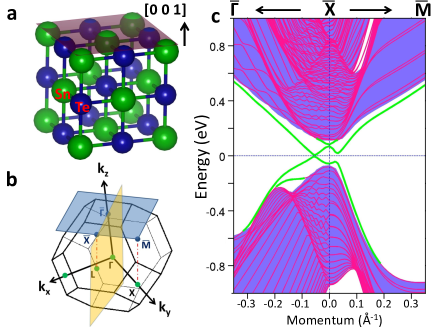
In order to clarify the relevant structural aspects, SnTe in an ideal sodium chloride FCC crystal structure is shown in Fig. 1a. Fig. 1b shows the FCC bulk Brillouin zone (BZ) as well as the [001] surface BZ. The high symmetry points , L and X in the bulk BZ are projected on the , X̄ and M̄ in the surface BZ, respectively. The [1 -1 0] mirror plane is perpendicular to the [001] surface plane and projected onto the surface BZ along the X̄ direction. The projected bulk band structure along the high symmetry lines -X̄-M̄ is shown in Fig. 1c by purple area. The surface bands are highlighted by thick green lines, isolated from other bulk bands. A gapless Dirac cone with the Dirac point sits along -X̄ on the two sides of the X̄ point at the Fermi level, while the surface states along X̄-M̄ are gapped.
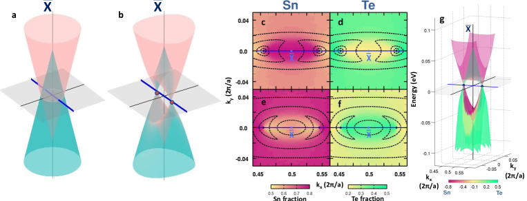
The complicated surface states of SnTe can be understood by a simpler picture, which consists of two Dirac cones. Fig. 2a shows two coaxial Dirac cones centered at the X̄ point. The X̄ and Ȳ points, i.e. (0.5, 0) and (0, 0.5), are equivalent and we concentrate on the one at (0.5,0) hereafter. These two Dirac cones carry different band characters and can be distinguished through an analysis of the wavefunctions of the Sn and Te atoms on the surface layers of the [001] slab. The nature of the differences in potentials of the Sn and Te atoms separates the two Dirac cones in energy vertically as shown in Fig. 2a. If there were no interactions between the two Dirac cone states, the two Dirac cones will intersect each other in the 2D surface BZ in an ellipse, which only intersects the mirror line along -X̄ (blue line) with two points on the two sides of the X̄ point. In Fig. 2b, when the interaction between the two Dirac cones is turned on, a gap opens up along the elliptical overlap region of the two Dirac cones, except at the two points protected by the mirror symmetry.
In order to trace the band character of the SnTe surface states, we decompose their charge distribution into Sn and Te partial contributions presented in Figs. 2c-f. For the surface valence states (Fig. 2c), we find that the Sn fraction is dominant within an elliptical region between the two Dirac points and centered at the X̄ point, while in Fig. 2d the Te fraction is larger outside this region. But, for the conduction surface states (Figs. 2e and f), this trend between the partial contributions from Se and Te atoms is reversed. To enhance visual clarity, we patch the charge fraction map onto the energy dispersion in Fig. 2g. These results of first-principles calculations qualitatively agree with the picture of two interacting Dirac cones shown in Fig. 2b and allow us to attribute the origin of the two coaxial Dirac cones to distinct atomic orbitals. One of the cones with opening to the high energy side is more Sn-like with -orbital, while the other cone with opening to the low energy side is more Te-like with -orbital. The Sn-like cone has the X̄-point Dirac point lower in energy than that of the Te-like cone.
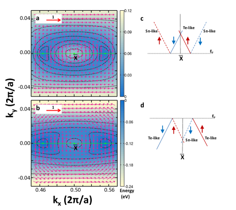
In Fig. 3, we plot surface band energies using a color scale and the associated constant energy contours, together with the in-plane spin-texture. The spin direction of each state was obtained here by calculating the expectation of the Pauli matrices from the first 6 atomic layers from the top surface of the SnTe slab. For the valence surface states shown in Fig. 3b, the highest energy state is located at the Dirac points lying along the X̄ mirror line. The constant energy contours close to the Dirac points are seen not to be of a perfect circular shape, which implies an anisotropic Fermi velocity around the Dirac points. Between two Dirac points, an energy valley is centered at the X̄ point. The energy contours exhibit a Lifshitz transitionNatliang . As we go to energies below the Fermi energy, the constant energy surface changes its topology. The two disconnected hole pockets next to the X̄ point at high energy become a large hole and a small electron pocket both centered at the X̄ point at low energy. In the two coaxial Dirac cones, the large hole pocket is associated with the Te-like lower Dirac cone and the small electron pocket is associated with the Sn-like upper Dirac cone. A similar change in the Fermi surface topology occurs in the conduction surface bands (Fig. 3a). At high energies above the interaction region, the large electron and small hole pocket centered at the X̄ point are associated with the Sn-like upper Dirac cone and the Te-like lower Dirac cone, respectively.
It is interesting to see how the spin-textures within our picture of two co-axial Dirac cones play out based on the spin-textures derived from our first-principles computations. Note that for the conduction bands shown in Fig. 3a, the spin texture shows counter-clockwise rotation around the X̄ point and clockwise rotation far away from the X̄ point. As shown in the schematic diagram of Fig. 3c, states near the X̄ point are associated with the Te-like lower Dirac cone while those far away from the X̄ point belong to the Sn-like upper Dirac cone. The two coaxial cones therefore should mimic similar chirality. They should both have clockwise spin rotation in the upper cone and counter-clockwise in the lower cone. Along the X̄ direction, these two opposite spin states meet at the Dirac points. Along the X̄M̄ direction, the spin polarization diminishes and switches direction around the Lifshitz transition. The spin texture of the valence surface states can be understood along similar lines. A clockwise rotation in the inner region around X̄ is associated with the Sn-like upper Dirac cone, while a counter-clockwise rotation in the outer region far away from the X̄ point is associated with the Te-like lower Dirac cone. We note that the spin chirality of the surface Dirac cone in a typical strong topological insulator like Bi2Se3HsiehBi is the same as that of the Sn-like and Te-like Dirac cones we have found here on the surface of SnTe, and bears a nontrivial mirror Chern number further discussed below.
III Simplified model
In order to make our proposed two-coaxial-cone picture more concrete, we now discuss a 2D model, which not only captures correctly the evolution in band dispersion under a Lifshitz transition, but also describes the spin texture reasonablyfoot1 ; ARFang . In this connection, it is natural to consider a minimal four-band model with Hamiltonian around X̄ point on the [001] surface, which obeys the following three symmetries: mirror symmetry about the plane (), mirror symmetry about the plane (), and time-reversal symmetry (, where for denotes complex conjugate). We then have under these symmetry operations, , and .
As shown in Fig. 2a, two distinct Dirac points occur at X̄, associated with energies and . [ denotes the energy level at which the two cones intersect.] To account for the doublet state at each Dirac point, we choose the basis set to be the eigenvectors of with eigenvalues : {, , , }, where the main atomic portion for each cone is indicated. In particular, when combined with the dominant orbitals for Sn () and Te () atoms mentioned earlier, this basis set also captures spin information, resulting in {, , , }. Note that the quantization axis for spin is now along , with and . Defining matrices, , with Pauli matrices and acting on spin and orbital spaces, respectively, the symmetry operator then takes the form, and the other two symmetry operators can be written as and . After examining the 16 matrices under all three symmetry operations, up to linear coupling in , , we obtain the following symmetry-allowed Hamiltonian,
| (1) | |||||
In Fig. 2b, we plot the energy dispersions based on this effective Hamiltonian, which is clearly seen to capture the key features of first-principles calculations (See Fig. 2g). The presence of two new Dirac points is due to the double degeneracy given by different eigenvalues and is thus protected by the mirror symmetry of the system about the plane, in sharp contrast to the Dirac points at X̄, which are mainly protected by the time-reversal symmetry. As to the spin texture, note that and now represent the in-plane spin and components, respectively. Furthermore, one can prove that for any eigenstate with momentum , (out-of-the-plane component), as required by the combined TRS and the two mirror symmetries: . It turns out that the resulting spin texture is qualitatively similar to that shown in Fig. 3. Finally, we note that if one applies a unitary transformation, , to Eq. (1), the transformed becomes
| (2) |
, where and . This is in fact a more familiar Hamiltonian, representing two interacting Dirac cones in the Rashba form, , with an identical chiralityfoot2 ; Fukpmodel . In Table. I, we list the parameter sets used in Eq. (2) by fitting experimentally obtained ARPES band dispersions in topologically nontrivial (Pb,Sn)TeARSuYang , SnTeARTanaka ; ARTanaka2 and (Pb,Sn)SeARDziawa ; ARMadhabN .
| Pb1-xSnxTe | SnTe | Pb1-xSnxSe | ||
| x=0.4 | x=0.23 | x=0.3 | ||
| -0.30 | -0.30 | -0.062 | -0.056 | |
| -0.15 | -0.15 | -0.036 | -0.026 | |
| -2.3 | -2.3 | -2.55 | -2.58 | |
| 0.0 | 0.0 | -0.64 | -0.32 | |
| -5 | -6.5 | -3.55 | -3.28 | |
| 0 | 0 | 0 | 0 | |
IV Discussion and conclusion
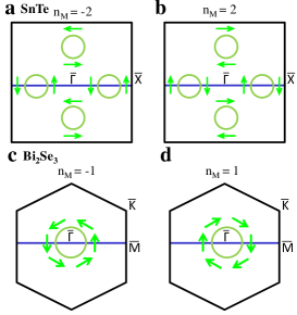
In general, topological crystalline insulators should harbor distinct classes with positive and negative mirror Chern numbers. The schematic diagrams of possible spin textures around the lower Dirac cones are given in Fig. 4. In Fig. 4a, a pair of Dirac cones with counter-clockwise spin texture on the horizontal mirror line gives the mirror Chern number n. The opposite case with a clockwise spin texture in Fig. 4b would give the mirror Chern number n. By comparing the spin-texture obtained from our first-principles calculations in Fig. 3, we can conclude that the mirror Chern number of SnTe is . For Bi2Se3 system shown in Fig. 4c, on a mirror line, only a single Dirac cone appears at the center of the hexagonal Brillouin zone with the mirror Chern number n. In Fig. 4d, if the spin texture runs clockwisely, the system has the mirror Chern number n. Since there are two coaxial Dirac cones in SnTe, where the Sn-like and Te-like Dirac cones exhibit the same spin charality as Bi2Se3, it follows that the mirror Chern number of SnTe is twice that of Bi2Se3.
In conclusion, we have delineated the charge density distributions and spin textures of the [001] surface states on the topological crystalline insulator SnTe via first-principles calculations. We show that the SnTe surface states can be pictured as two interacting coaxial Dirac cones which intersect each other to form the Dirac points along the mirror symmetry line X̄. From an examination of the charge distribution, we attribute the origin of the two coaxial Dirac cones to the two distinct atomic species, Sn and Te, in the material. The crystal and time-reversal symmetries guarantee that the out-of-the-plane spin polarization is zero. The spin texture is dictated by the non-trivial Chern number n in SnTe, which is different from the known Z2 topological insulators such as Bi2Se3.
Acknowledgments: It is a pleasure to thank Liang Fu and Chen Fang for useful discussions. The work at Northeastern and Princeton is supported by the Division of Materials Science and Engineering, Basic Energy Sciences, U.S. Department of Energy Grants DE-FG02-07ER46352, DE-FG-02-05ER46200 and AC02-05CH11231, and benefited from theory support at the Advanced Light Source, Berkeley, and the allocation of supercomputer time at NERSC and Northeastern University’s Advanced Scientific Computation Center (ASCC). M.Z.H is supported by NSF-DMR-1006492 and DARPA-N66001-11-1-4110. W.F.T is supported by the NSC in Taiwan under Grant No. 100-2112-M-110-001-MY2.
References
- (1) M. Z. Hasan, and C. L. Kane, Rev. Mod. Phys. 82, 3045-3067 (2010).
- (2) X.-L. Qi, and S.-C. Zhang, Rev. Mod. Phys. 83, 1057 (2011).
- (3) M. Z. Hasan, and J. E. Moore, Annual Review of Condensed Matter Physics 2, 5578 (2011).
- (4) M. Konig, H. Buhmann, L. W. Molenkamp, T. Hughes, C-X Liu, X-L Qi and S-C Zhang, J. Phys. Soc. Japan 77, 031007 (2008)
- (5) L. Fu and C.L. Kane, Phys. Rev. B 76, 045302 (2007).
- (6) D. Hsieh, D. Qian, L. Wray, Y. Xia, Y. S. Hor, R. J. Cava and M.Z. Hasan, Nature, 452, 970 (2008).
- (7) Hsieh D et al., Nature 460, 1101 (2009)
- (8) L. Fu, Phys. Rev. Lett. 106, 106802 (2011)
- (9) Timothy H. Hsieh et al., Nature Communications 3, 982 (2012)
- (10) Su-Yang Xu et al., Nature Communications 3, 1192 (2012)
- (11) Y. Tanaka et al., Nature Physics 8, 800 (2012)
- (12) P. Dziawa et al., Nature Materials 11, 1023 (2012)
- (13) Teo, J. C. Y. , Fu, L., and Kane, C.L. Phys. Rev. B 78, 045426 (2007).
- (14) R. Takahashi and S. Murakami Phys. Rev. Lett. 107, 166805 (2011).
- (15) G. Kresse and D. Joubert, Phys. Rev. B 59, 1758 (1999).
- (16) J. P. Perdew, K. Burke and M. Ernzerhof, Phys. Rev. Lett. 77, 3865 (1996)
- (17) G. Kresse and J. Hafner, Phys. Rev. B 48, 13115 (1993)
- (18) R. F. Bis and J. R. Dixon, J. Appl. Phys. 40, 1918 (1969)
- (19) C. Fang et al.ARFang considered a similar approach but without any spin information.
- (20) C. Fang et al., arXiv:1212.3285
- (21) The picture of two degenerate Dirac cones given in the recent work by J. Liu et al.Fukpmodel can be obtained via a unitary transformation of our Hamiltonian, and is thus equivalent to our model.
- (22) J. Liu, W. Duan and L. Fu, arXiv:1304.0430.
- (23) Y. Tanaka et al., arXiv:1301.1177
- (24) M. Neupane et al., in preparation