Interplay between symmetry and spin-orbit coupling in graphene nanoribbons
Abstract
We study the electronic structure of chiral and achiral graphene nanoribbons with symmetric edges, including curvature and spin-orbit effects. Curved ribbons show spin-split bands, whereas flat ribbons present spin-degenerate bands. We show that this effect is due to the breaking of spatial inversion symmetry in curved graphene nanoribbons, while flat ribbons with symmetric edges possess an inversion center, regardless of their having chiral or achiral edges. We find an enhanced edge-edge coupling and a substantial gap in narrow chiral nanoribbons, which is not present in zigzag ribbons of similar width. We attribute these size effects to the mixing of the sublattices imposed by the edge geometry, yielding a behavior of chiral ribbons that is distinct from those with pure zigzag edges.
pacs:
PACS number(s): 71.20.Tx, 73.22.-f, 71.70.EjI Introduction
The crucial interplay between structure and electronic properties of graphene is among the most attractive features of its derived nanomaterials. Both carbon nanotubes (CNTs) and graphene nanoribbons (GNRs) show promising characteristics for spintronic devices. Recent progress in experimental techniques has allowed for the fabrication of graphene nanostripes by using electron-beam lithographyCastro Neto et al. (2009) or by unrolling CNTs.Kosynkin et al. (2009) These ribbons could be used in electronic devices, such as field-effect transistors,Lin et al. (2011) opening new perspectives for nanoelectronics.
The presence of localized edge states in GNRs, theoretically predicted, Fujita et al. (1996); Wakabayashi et al. (2010) and experimentally proved, Niimi et al. (2006) confers them distinct properties. GNRs have attracted a great amount of theoretical work, but mostly focused on high-symmetry zigzag and armchair achiral ribbons. Zigzag ribbons have edges states with different spin polarizations, while armchair nanoribbons do not have edge states. The edges of minimalAkhmerov and Beenakker (2008); Jaskólski et al. (2011) chiral ribbons can be considered as a mixture of armchair and zigzag edges, thus having edge-localized states stemming from their zigzag part. Although the evolution of the nanoribbon band structure upon the change of chirality has been recently addressed,Wakabayashi et al. (2009); Wakabayashi and Dutta (2012); Yazyev et al. (2011) these systems have been nonetheless much less studied and many aspects remain to be explored.
The seminal work of Kane and Mele Kane and Mele (2005) triggered the interest on new quantum phases of matter and on the spin-orbit coupling (SOC) effect which, although known to be small in graphene, gives rise to important physics. In particular, the quantum spin Hall (QSH) phase has been widely addressed.Hasan and Kane (2010); Beugeling et al. (2012)
Curvature is known to enhance spin-orbit interaction; its importance in SOC effects has been theoretically investigated for the honeycomb lattice, especially for CNTs,Ando (2000); Chico et al. (2004); Huertas-Hernando et al. (2006); Chico et al. (2009); Izumida et al. (2009); Chico et al. (2012) and experimentally confirmed.Kuemmeth et al. (2008) Hybridization of and orbitals, decoupled in flat graphene, is enhanced by curvature and thus SOC effects are bolstered.Chico et al. (2009) The interplay between curvature and SOC in GNRs has been mostly focused in achiral ribbons, with highly symmetric zigzag and armchair edges.Zarea and Sandler (2009); López-Sancho and Muñoz (2011); Gosálbez-Martínez et al. (2011) For zigzag GNRs, dispersionless edge bands in the flat geometry were found to become dispersive because of SOC effects. Both and edge states remain spin-filtered in the curved geometry, still localized at the boundaries of the ribbon, albeit with an in-plane spin component and a localization length larger than for the flat case.López-Sancho and Muñoz (2011) Recent experimentsSantos et al. (2009); Kosynkin et al. (2009); Tao et al. (2011) on chiral GNRs obtained by unzipping CNTs show a reminiscent curvature. Scanning tunneling spectroscopy measurements revealed the presence of one-dimensional edge states, with an energy splitting dependent on the width of the ribbon.Tao et al. (2011) By comparison with calculations employing a -band model with a Hubbard term the width dependence of the edge state gap was interpreted as a consequence of spin-polarized edge states.Tao et al. (2011); Yazyev et al. (2011) Hence, the study of curvature effects in GNRs is relevant from the experimental and theoretical viewpoint.
In this paper we address the study of this ampler
class of ribbons with chiral edges, focusing on the differences of SOC effects in flat and curved nanoribbons.
We summarize our main results as follows:
(i) We find that the bands of both, chiral and achiral, flat ribbons with symmetric edges are at least twofold spin degenerate due to spatial inversion symmetry. Curving the ribbons breaks this symmetry, thus yielding spin-split bands except for the time-reversal protected special symmetry points.
(ii) We find a gap in all chiral ribbons, despite the fact that they have a zigzag edge component.
Boundary conditions in chiral ribbons mix both sublattices at each edge. This enhances edge-edge coupling, which results in a substantial gap without invoking electron interactions.
(iii) Curvature augments spin-orbit effects in GNRs, yielding a larger splitting in the spin-split bands. In fact, curvature may induce metallicity in ribbons which have a gap in the planar form.
(iv) The spatial distribution of edge states depends on curvature and chirality. While zigzag ribbons are known to have spin-filtered states at the edges, in narrow ( Å) chiral ribbons edge states can have nonzero density at both edges, due to the edge-edge coupling. This size effect is more evident in ribbons with chiral angle close to , i.e., that of the armchair edge, for which the sublattice mixing is stronger.
This paper is outlined as follows. Section II describes the structure and geometry of the ribbons studied. Section III gives some symmetry considerations concerning the role of spatial inversion in flat and curved general ribbons. Section IV contains the description of the model Hamiltonian and calculation method. Section V presents the results, including spin-orbit interaction, for ribbons of different widths in flat and curved geometries. Finally, in Section VI we discuss our results and final conclusions are drawn.
II Geometry
We focus on chiral ribbons with symmetric minimal edges,Akhmerov and Beenakker (2008) obtained from unrolling chiral carbon nanotubes. The ribbon is thus characterized by the edge vector , where and are the primitive vectors of graphene, and the width vector . The widths considered are therefore given by an integer multiple of , defined as the smallest graphene lattice vector perpendicular to , as depicted in Fig.1. For a given , is uniquely determined up to a global factor. As , we will denote the ribbons by , where states the width of the ribbon, and indicates the minimal edge. All minimal edges can be decomposed in a zigzag and an armchair part,Akhmerov and Beenakker (2008); Jaskólski et al. (2011) , with and .
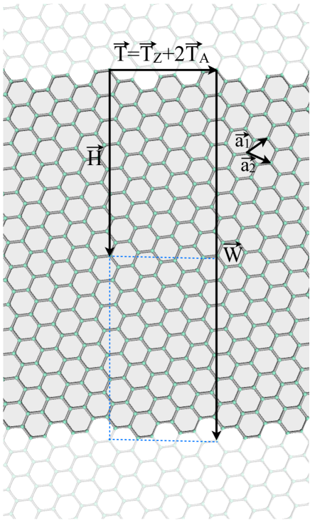
The chirality of the ribbon is specified by the chiral angle between the translation vector which defines the edges and the zigzag direction (1,0).
We take into account different curvatures in the transversal direction for a given flat GNR, with no stretching allowed. Curvature is denoted by the angle spanned by the ribbon from its curvature center, ranging from zero for a flat ribbon to a value of 2, which corresponds to a nanotube with cut bonds along its length. The degree of curvature is controlled by the angle and by the diameter of the cylindrical configuration.
III Symmetry considerations
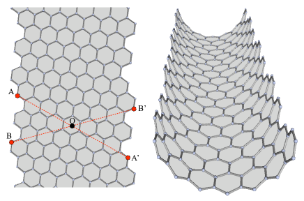
Carbon nanotubes are classified as achiral and chiral according to their having a symmorphic or non-symmorphic symmetry group, respectively. This means that chiral tubes possess an spiral symmetry, so that there are two enantiomers for each chirality, while achiral tubes are equal to their mirror image; i.e., achiral tubes present space inversion symmetry while chiral tubes do not.Saito et al. (1998); Charlier et al. (2007) Graphene nanoribbons, like their siblings carbon nanotubes, are customarily classified as achiral and chiral according to their edge shapes. In GNRs this classification is related to the crystallographic orientation of the boundaries: ribbons with zigzag and armchair edges (derived from armchair and zigzag CNTs, respectively) are called achiral, and those obtained from chiral tubes are called chiral GNRs. However, these so-called chiral ribbons with symmetric edges do have an inversion center. Upon bending the ribbon the inversion symmetry is lost. This feature is crucial when considering SOC effects. Fig. 2 shows an example of a flat (left panel) and curved (right panel) unit cell of the (3,2) ribbon, the latter with . A symmetry center is indicated in the planar geometry. No such inversion center exists in the curved nanoribbon.
Notice that a flat nanoribbon with different edges lacks inversion symmetry. This situation is of experimental interest: most likely, actual ribbons will not have symmetric edges. Such asymmetry can be achieved either by adding or removing atoms to an originally edge-symmetric ribbon, or by altering the bond lengths in one of the edges. Dissimilar bond lengths may arise as a result of a different functionalization on the two edges of the nanoribbon.
IV Theoretical model and computational methods
We calculate the band structure of graphene within the empirical tight-binding (ETB) approximation. Although the -orbital tight-binding model is known to capture the low energy physics of graphene, since we are interested in SOC effects, we consider here an orthogonal four-orbital , , , basis set. This allows for the inclusion of the intrinsic SO terms within the conventional on-site approach. The matrix Hamiltonian is built following the Slater-Koster formalism up to nearest-neighbor hopping. We use the parametrization obtained by Tománek-Louie for graphite.Tománek and Louie (1988) The expression of the one-electron ETB Hamiltonian is
| (1) |
where represents the atomic energy of the orbital , stands for all the atomic sites of the unit cell of the GNR, and and are the creation and annihilation operators, respectively, of one electron at site , orbital , and spin . We focus on neutral graphene; thus, no doping effects are addressed.
SOC effects are included by adding an atomic-like term to the Hamiltonian. Assuming that the most important contribution of the crystal potential to the spin-orbit coupling is close to the cores, the contribution takes the form
where the spherical symmetry of the atomic potential has been assumed and is the radial coordinate with origin at the atom. stands for the orbital angular momentum of the electron, and is the spin operator. The parameter is a renormalized atomic SOC constant which depends on the orbital angular momentum. Notice that the terms only couple orbitals in the same atom. Considering the spin parts of the wave functions, the Hamiltonian matrix has elements, being the number of the C atoms in the unit cell of the GNR and 8 corresponding to the four orbitals per spin of the basis set. The total Hamiltonian in the block spinor structure is given by
| (2) |
The total Hamiltonian incorporates both, spin conservation and spin-flip terms. The spin-conserving diagonal terms act as an effective Zeeman field producing gaps at the and points of the graphene Brillouin zone (BZ), with opposite signs.Chico et al. (2009) By exact diagonalization of the matrix we obtain the band structure of GNRs. As explained in the previous section, the curved geometry is obtained by isotropically bending the ribbon in the width direction, without changing the distance along its length. Thus, no bond stretching is included along the ribbon axis. We do not consider reconstruction or relaxation of the edges or passivation of the dangling bonds.
The value of the SOC constant for C-based materials is not well established and it is still under debate. Some theoretical estimates gave eV for graphene,Min et al. (2006); Zarea and Sandler (2007) much smaller than the atomic SO coupling, 8 meV. Taking into account the role of orbitals, this value raises to eV.Konschuh et al. (2010) Accurate measurements of SOC are difficult to perform in graphene because external effects such as substrates, electric fields, or impurities may mask its value. However, recent experiments in CNT quantum dots have reported spin-orbit splittings substantially higher than those theoretically predicted: Kuemmeth et al. Kuemmeth et al. (2008) give a maximum splitting of 0.37 meV in a CNT of diameter 5 nm. One possible explanation for this energy splitting is that a higher value of should be considered; as indicated by Izumida et al.,Izumida et al. (2009) those measurements are compatible with meV. More recently, Steele et al. Steele et al. (2013) have presented evidence of large spin-orbit coupling in CNTs, up to 3.4 meV, an order of magnitude larger than previously measured and the largest theoretical estimates. Furthermore, transport experiments report spin-relaxation times in graphene 1000 times lower than predicted.Lundeberg et al. (2013) This is compatible with a larger value of the SOC coupling than those given by previous theoretical estimates.Min et al. (2006); Zarea and Sandler (2007); Konschuh et al. (2010) Although small, its effects in GNRs could have important consequences when considering the spin degree of freedom, as has been experimentally shown in CNTs.Kuemmeth et al. (2008); Steele et al. (2013) For the sake of clarity, we choose for the Figures a spin-orbit interaction parameter eV.
The spin-orbit contribution to the Hamiltonian, is linear on . We have checked that, for small values of this parameter, such as the one employed here and those of physical relevance, the eigenvalues of the full Hamiltonian are basically a linear correction to those without the SOC term, . Therefore, the spin-orbit splittings are proportional to and the results presented in this work can be scaled accordingly.
V Results
We have calculated the electronic properties of many different chiral GNRs, varying their width and curvature. All calculations have been performed with the four-orbital parametrization explained in Sec. IV. Therefore, they show some differences with respect to the widely used one-orbital approach.Yazyev et al. (2011) We present here the band structures for three representative chiral ribbons [, , and ] and, for comparison, some zigzag GNRs of different widths. The ribbon has a chiral angle , close to the zigzag direction; the has ; and the GNR has , closer to the armchair direction. The and GNRs have the same unit cell with 76 atoms, but with different orientation; i.e., the and vectors are interchanged. The ribbon, in the intermediate chirality range, has a unit cell with 52 atoms. The (5,2) edge has three armchair () and two zigzag () units, so for the infinite system there are two possible arrangements of the armchair and zigzag units with the same edge vector. We choose the one with all zigzag units together, the . While the edge states in a semi-infinite graphene sheet or in very wide ribbons are the same irrespectively of the sequence, for narrow ribbons some differences in the band structure of distinct edge arrangements may arise.
V.1 SOC and inversion symmetry
V.1.1 Curvature effects
In systems with time-reversal and spatial inversion symmetry, spin-orbit interaction does not lift spin degeneracy, according to Kramers’ theorem. If spatial inversion symmetry is not present, the states are spin-split except in the points protected by time reversal invariance. In symmetric-edge GNRs, spatial inversion symmetry is broken by curving the ribbon, as indicated in Fig. 2. The importance of the broken inversion symmetry is shown in Fig. 3, where the electronic structures of the 1(7,1) ribbon calculated with and without SOC terms are depicted for (a) the planar configuration and (b) the curved one with . This angle corresponds to a maximally curved geometry without overlapping the edges of the ribbon; it is equivalent to an open carbon nanotube with circumference equal to the width of the GNR. SOC effects are clear: all degeneracies, including spin, are lifted in the curved ribbon (b), while in the flat system (a) the bands remain spin-degenerated. The only noticeable difference in the flat case is a small shift in the bands at the point, as it can be observed in the zoom of Fig. 3. Otherwise, the effect of SOC is negligible. However, a large splitting is found in the curved ribbons, greater for the conduction bands. This is due to the interaction of edge states with higher-energy bands (see zoom in Fig. 3 (b)), which in fact are completely hybridized due to curvature. Throughout most of the BZ, one of the spin-split bands has an upward shift in energy, whereas the other band undergoes a downshift. Thus, the bands without SOC mostly lie between the spin-orbit-split bands, as it can be seen in Fig. 3 (b), especially in the zoom.
Notice that GNRs can be made metallic because of the curvature, as seen in Fig. 3: the gap observed in the flat 1(7,1) ribbon (panel (a)) is still present at in the curved () geometry, but in this latter case the ribbon is metallic due to the band bending produced by curvature-induced hybridization (panel (b)).
Although the spin is no longer a good quantum number, the expectation value of the spin operator shows that in the flat geometry the total spin is normal to the ribbon. Curvature provokes the appearance of a small component in the in-plane direction which increases with curvature.
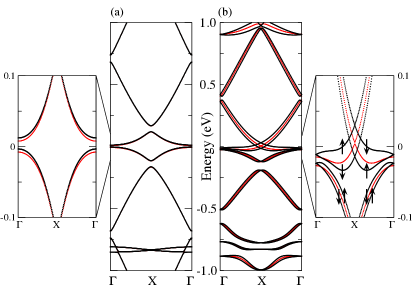
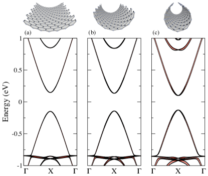
Fig. 4 illustrates the effect of curvature. It presents the band structure of the 1(3,2) ribbon for three bending angles, namely, (a) 0.5; (b) 1.2, and (c) 1.8, with (black dots) and without (red/gray dots) SOC.The curved geometries are shown above each band panel. In a wide ribbon there are four edge bands at 0 eV extending from to .Jaskólski et al. (2011) In the case depicted in Fig. 4 a large gap opens between the occupied and unoccupied edge bands due to size effects, which we discuss later on. There is a general increase of the band splitting with growing curvature, as expected, due to the increment of the - hybridization produced in the curved ribbons, analogous to the effect predictedChico et al. (2004, 2009) and experimentally measured in CNTs.Kuemmeth et al. (2008) Moreover, band splitting in GNRs is anisotropic, band- and -dependent, as also found in CNTs.
V.1.2 Edge modification
As discussed above, planar GNRs with dissimilar edges also lack inversion symmetry. Different edges can be achieved either by adding or removing atoms in a symmetric edge ribbon, or by altering the bond lengths at one edge of a symmetric GNR. We have explored the magnitude of this effect, calculating the changes in the band structure of a planar 1(5,2) modified ribbon. We have considered two types of modifications: two atoms of one edge have been removed, and the bond length of the zigzag atoms at one edge has been changed 10%. With both modifications SOC breaks the spin degeneracy of the band structure; however, the splitting is two orders of magnitude smaller than that achieved by the effect of curvature. Thus, in what follows, we concentrate on the curvature mechanism as a means to break inversion symmetry.
V.2 SOC effects and width of the ribbon
In order to explore the interplay of SOC and the width of the ribbon we consider first flat GNRs, since in curved geometries they could be masked by other effects, such as hybridization. We have performed calculations for different chiralities, verifying that there is a gap in planar chiral nanoribbons that decreases with increasing width. Panels (a) to (c) of Fig. 5 demonstrate this effect for the GNRs. The 1(5,2) ribbon has a substantial gap, around 0.4 eV, while the flat bands around for the 4(5,2) ribbon in panel (c) are clearly identified as edge bands for their dispersionless character near the BZ boundary X. Nonetheless, the gap can be discerned in the inset of Fig. 5 (c), as stated above.
Comparison with high-symmetry zigzag ribbons of similar widths shows a striking difference. Figure 5 demonstrates that zigzag ribbons have a negligible energy gap, around 0.1 meV for the narrowest case depicted [Fig. 5 (d), Å], while for the 1(5,2) ribbon of similar width (8.87 Å) the gap is around 0.4 eV.
The gaps between edge bands in chiral ribbons are due to the stronger coupling between edge states localized at each boundary. In zigzag ribbons the atoms at opposite edges belong to different sublattices, while in chiral ribbons boundary conditions at each edge mix the two sublattices, coupling the states located at the two edges. This results in a band gap due to quantum size effects, without invoking electron-electron interactions.
In flat ribbons, SOC induces a tiny shift of the energy bands; in zigzag ribbons, it turns the flat edge bands into dispersive ones. As inversion symmetry is preserved, all bands remain spin degenerated.
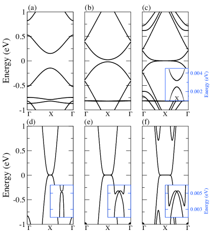
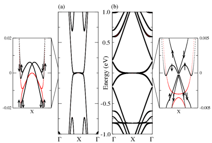
Now, we include curvature in order to enhance SOC effects and break spin degeneracy, as discussed in the previous Section. For narrow chiral ribbons the gap due to quantum size effects is rather large, as it can be seen in Figs. 5 (a) and (b), so the effect of SOC is the aforementioned energy shift and, most importantly, the spin splitting of the bands. We focus on the widest ribbons, namely, the 4(5,2) and the 8(1,0), with a smaller quantum size gap, and consider the same curvature radius for both ribbons, Å, which yields an angle and , respectively. For these cases, the bands closer to are strongly deformed. These happen to be edge states, so their behavior gives rise to a more interesting situation than in the large gap ribbons, as it is illustrated in Fig. 6.
Fig. 6 (a) shows the zigzag case, with a noticeable dispersion in the edge bands. The zoom shows that the bands with SOC are spin-split, with a crossing point slightly shifted with respect to that of the bands without SOC. Fig. 6 (b) shows the chiral 4(5,2) GNR; here besides the energy shift and spin-splitting of the SOC bands, there is a slight displacement of the Fermi wavevector, which is no longer at X Although small, SOC effects have important consequences for the transport properties of curved GNRs: spin-filtered channels arise due to the interplay of SOC and curvature, and for wider ribbons, even chiral GNRs present these spin-filtered channels in the low-energy region.
V.3 Chirality and spatial distribution of edge states
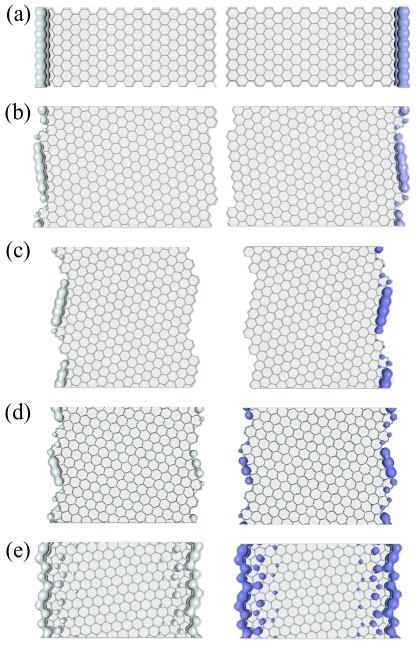
Edge states are among the most important features of GNRs.Wakabayashi et al. (2009); Wakabayashi and Dutta (2012) It is interesting to explore how chirality affects the behavior of these states. For the sake of simplicity, we focus on flat geometries; generalization to curved geometries is straightforward. In Fig. 7 we present the electronic densities of edge states belonging to flat ribbons with different chiralities. The two states chosen correspond to the edge bands closer to the Fermi level, near the high-symmetry point to which the edge bands converge for large widths. Opposite spin polarizations are indicated with distinct colors; since we are dealing with flat ribbons, the spin direction is perpendicular to the plane of the ribbon. We choose a value slightly displaced from the symmetry point (either or the BZ boundary X) in order to avoid degeneracy due to time reversal invariance, and ribbons of similar width in order to compare size effects. In pure zigzag ribbons, edge states are spin-filtered: each edge state has a well-defined spin orientation and it is located at one edge. This is illustrated in Fig. 7 (a), which shows the square modulus of the wave functions for two edge states corresponding to a 10(1,0) zigzag nanoribbon, of width equal to 42.61 Å. These two edge states of zigzag ribbons live in opposite sublattices, and their probability density is mostly confined to the atoms with coordination number 2 which constitute the geometrical edge. Fig. 7 (b) shows the density for two edge states of a 4(7,1) ribbon of width 42.89 Å, close in chirality to the zigzag case. Similarly to the zigzag ribbon, the density of each edge is mostly located in one sublattice. It is not homogeneously distributed, being mostly in atoms with coordination number 2, although there is some appreciable weight in inner atoms close to the edge. For the 1(7,2) GNR (of width 34.88 Å and ) [Fig. 7 (c)], which has a larger chirality angle, the wave function extends more into inner atoms, especially close to the armchair part of the boundary.
For chiralities closer to the armchair, the states have a nonzero density at both edges: panel (d) shows the two states close to for a 4(5,2) ribbon of width 35.48 Å. These two states live at both edges simultaneously, with more inner atoms with nonzero density. This is more dramatic in panel (e) of Fig. 7, which depicts the edge states for a 2(3,2) ribbon of width 37.40 Å. As its chirality is closer to the armchair case, edge states have a greater penetration into the inner part of the ribbon. In order to localize these states and obtain the quantum spin Hall phase, a larger value of the SOC constant ( eV) is needed. This behavior has been found for armchair ribbons within the Dirac modelZarea and Sandler (2007) and the ETB model.López-Sancho and Muñoz (2011) The SOC strength required increases with the chiral angle and decreases with the width of the ribbon.
In curved ribbons, edge states keep their localized character, even for the maximum curvature. Besides the spin splitting (Fig. 6), there are two main differences: the spatial localization length is larger for the curved ribbon than for the flat case, and the spin direction changes from the direction normal to the ribbon surface, acquiring a component in the ribbon plane, as previously reported.López-Sancho and Muñoz (2011); Gosálbez-Martínez et al. (2011)
VI Discussion and conclusions
Our results show that the relation between the QSH edge states of graphene nanoribbons and both, the crystallographic orientation of the edges and the curvature of the GNR, allows us to control the spin and spatial localization of the ribbon edge states. Consequently, this may allow us to achieve an efficient electrical control of spin currents and spin densities in GNRs. Taking into account both spin and valley degeneracy, Bloch states in graphene are four-fold degenerate. SOC splits them into two Kramers doublets and, as Kane and Mele predicted,Kane and Mele (2005) this turns graphene into a topologically non-trivial material. In zigzag edge ribbons, it has already been shown that at each edge spin-up and spin-down electrons move in opposite directions.López-Sancho and Muñoz (2011); Chico et al. (2012) Since backscattering in a given edge requires the reversal of spin it cannot be induced by spin-independent scatterers. Accordingly, edge states in zigzag GNRs are topologically protected and hence the conductance of the edge states is quantized. However, in flat chiral-edge GNRs of finite width and for realistic values of the SOC strength, there is a non-zero probability of having electrons moving in opposite directions with the same spin polarization at a given edge (see fig. 7). Therefore, intra-edge backscattering may occur, which affects the quantization of the conductance. In chiral-edge GNRs, spin reversal can be induced even by non-magnetic disorder and thus edge states do not present a robust conductance quantization. The appearance of backscattering does depend on the chirality angle, increasing for angles approaching the armchair limit. On the other hand, curvature breaks the inversion symmetry of the ribbons and Bloch states are spin-split. Electrons with the same spin and opposite propagating directions in a given edge have different energies. As a result, backscattering is not allowed and in curved chiral-edge GNRs, edge states behave as robust quantum channels. Therefore, these chiral ribbons present a magneto-mechanical effect: upon curving the ribbon, the spin channels are split in energy, thus allowing for spatially separated spin currents.
Despite the weakness of SOC in these carbon systems,—on the scale of a few meV—, their effects in curved graphene and nanotubes are not negligible, due to the coupling of and bands in curved geometries. Thus, although small, the effects discussed in this work may be physically relevant, and since in graphene the position of the Fermi level can be adjusted with external gate voltages, the control of spin currents in GNR-derived devices could be possible.
In summary, we have shown that, in the presence of spin-orbit interaction, curvature breaks spin degeneracy in graphene ribbons. Flat nanoribbons with symmetric edges, either chiral or achiral, have spin-degenerate bands. This is due to the existence of spatial inversion symmetry in flat ribbons, which is broken in the curved cases. Furthermore, spin-orbit splitting is enhanced in curved ribbons due to the hybridization of the bands, absent in flat samples. Other mechanisms to break inversion symmetry, such as edge modification, are much less efficient to remove spin degeneracy.
We have also explored finite-size effects in GNRs. We find that narrow chiral ribbons present a sizable gap, despite their having a zigzag edge component, whereas in pure zigzag GNRs of similar width the gap is negligible. We relate this behavior to the boundary conditions in chiral edges, which mix the two sublattices at each edge. Finally, we have studied the chirality dependence on the spatial localization of edge states. In narrow chiral ribbons, edge states have a nonzero density at both edges simultaneously, due to edge coupling. Due to the sublattice mixing produced by the chiral boundary conditions, edge states have a larger penetration than those of achiral ribbons. For wider curved ribbons, they behave as spin-filtered states, being localized at one edge.
VII Acknowledgments
H. S. gratefully acknowledges helpful discussions with J. E. Alvarellos. This work has been partially supported by the Spanish Ministries of Science and Innovation (MICINN) and Economy and Competitiveness (MINECO) DGES under grants MAT2009-14578-C03-03, PIB2010BZ-00512, FIS2010-21282-C02-02, FIS2011-23713, MAT2012-38045-C04-04, and FIS2012-33521.
References
- Castro Neto et al. (2009) A. H. Castro Neto, F. Guinea, N. M. R. Peres, K. S. Novoselov, and A. K. Geim, Rev. Mod. Phys., 81, 109 (2009).
- Kosynkin et al. (2009) D. V. Kosynkin, A. L. Higginbotham, A. Sinitskii, J. R. Lomeda, A. Dimiev, B. K. Price, and J. M. Tour, Nature, 458, 872 (2009).
- Lin et al. (2011) Y.-M. Lin, A. Valdes-Garcia, S. Han, D. B. Farmer, I. Meric, Y. Sun, Y. Wu, C. Dimitrakopoulos, A. Grill, P. Avouris, and K. Jenkins, Science, 332, 1294 (2011).
- Fujita et al. (1996) M. Fujita, K. Wakabayashi, K. Nakada, and K. Kusakabe, J. Phys. Soc. Jpn., 65, 1920 (1996).
- Wakabayashi et al. (2010) K. Wakabayashi, S. Okada, R. Tomita, S. Fujimoto, and Y. Natsume, J. Phys. Soc. Jpn., 79, 034706 (2010).
- Niimi et al. (2006) Y. Niimi, T. Matsui, H. Kambara, K. Tagami, M. Tsukada, and H. Fukuyama, Phys. Rev. B, 73, 085421 (2006).
- Akhmerov and Beenakker (2008) A. R. Akhmerov and C. W. J. Beenakker, Phys. Rev. B, 77, 085423 (2008).
- Jaskólski et al. (2011) W. Jaskólski, A. Ayuela, M. Pelc, H. Santos, and L. Chico, Phys. Rev. B, 83, 235424 (2011).
- Wakabayashi et al. (2009) K. Wakabayashi, Y. Takane, M. Yamamoto, and M. Sigrist, Carbon, 47, 124 (2009).
- Wakabayashi and Dutta (2012) K. Wakabayashi and S. Dutta, Solid State Commun., 152, 1420 (2012).
- Yazyev et al. (2011) O. V. Yazyev, R. B. Capaz, and S. G. Louie, Phys. Rev. B, 84, 115406 (2011).
- Kane and Mele (2005) C. L. Kane and E. J. Mele, Phys. Rev. Lett., 95, 226801 (2005).
- Hasan and Kane (2010) M. Z. Hasan and C. L. Kane, Rev. Mod. Phys., 82, 3045 (2010).
- Beugeling et al. (2012) W. Beugeling, N. Goldman, and C. Morais Smith, Phys. Rev. B, 86, 075118 (2012).
- Ando (2000) T. Ando, J. Phys. Soc. Jpn., 69, 1757 (2000).
- Chico et al. (2004) L. Chico, M. P. López-Sancho, and M. C. Muñoz, Phys. Rev. Lett., 93, 176402 (2004).
- Huertas-Hernando et al. (2006) D. Huertas-Hernando, F. Guinea, and A. Brataas, Phys. Rev. B, 74, 155426 (2006).
- Chico et al. (2009) L. Chico, M. P. López-Sancho, and M. C. Muñoz, Phys. Rev. B, 79, 235423 (2009).
- Izumida et al. (2009) W. Izumida, K. Sato, and R. Saito, Journal of the Physical Society of Japan, 78, 074707 (2009).
- Chico et al. (2012) L. Chico, H. Santos, M. C. Muñoz, and M. P. López-Sancho, Solid State Commun., 152, 1477 (2012).
- Kuemmeth et al. (2008) F. Kuemmeth, S. Ilani, D. C. Ralph, and P. L. McEuen, Nature (London), 452, 448 (2008).
- Zarea and Sandler (2009) M. Zarea and N. Sandler, Phys. Rev. B, 79, 165442 (2009).
- López-Sancho and Muñoz (2011) M. P. López-Sancho and M. C. Muñoz, Phys. Rev. B, 83, 075406 (2011).
- Gosálbez-Martínez et al. (2011) D. Gosálbez-Martínez, J. J. Palacios, and J. Fernández-Rossier, Phys. Rev. B, 83, 115436 (2011).
- Santos et al. (2009) H. Santos, L. Chico, and L. Brey, Phys. Rev. Lett., 103, 086801 (2009).
- Tao et al. (2011) C. Tao, L. Jiao, O. V. Yazyev, Y.-C. Chen, J. Feng, X. Zhang, R. B. Capaz, J. M. Tour, A. Zettl, S. G. Louie, H. Dai, and M. F. Crommie, Nature Phys., 7, 616 (2011).
- Saito et al. (1998) R. Saito, G. Dresselhaus, and M. S. Dresselhaus, Physical Properties of Carbon Nanotubes (Imperial College Press (London), 1998).
- Charlier et al. (2007) J. C. Charlier, X. Blase, and S. Roche, Rev. Mod. Phys., 79, 677 (2007).
- Tománek and Louie (1988) D. Tománek and S. G. Louie, Phys. Rev. B, 37, 8327 (1988).
- Min et al. (2006) H. Min, J. E. Hill, N. A. Sinitsyn, B. R. Sahu, L. Kleinman, and A. H. MacDonald, Phys. Rev. B, 74, 165310 (2006).
- Zarea and Sandler (2007) M. Zarea and N. Sandler, Phys. Rev. Lett., 99, 256804 (2007).
- Konschuh et al. (2010) S. Konschuh, M. Gmitra, and J. Fabian, Phys. Rev. B, 82, 245412 (2010).
- Steele et al. (2013) G. Steele, F. Pei, E. Laird, J. Jol, H. Meerwaldt, and L. Kouwenhoven, Nature Communications, 4, 1873 (2013).
- Lundeberg et al. (2013) M. B. Lundeberg, R. Yang, J. Renard, and J. A. Folk, Phys. Rev. Lett., 110, 156601 (2013).