Unidirectional Amplification and Shaping of Optical Pulses by Three-Wave Mixing with Negative Phonons
Abstract
A possibility to greatly enhance frequency-conversion efficiency of stimulated Raman scattering is shown by making use of extraordinary properties of three-wave mixing of ordinary and backward waves. Such processes are commonly attributed to negative-index plasmonic metamaterials. This work demonstrates the possibility to replace such metamaterials that are very challenging to engineer by readily available crystals which support elastic waves with contra-directed phase and group velocities. The main goal of this work is to investigate specific properties of indicated nonlinear optical process in short pulse regime and to show that it enables elimination of fundamental detrimental effect of fast damping of optical phonons on the process concerned. Among the applications is the possibility of creation of a family of unique photonic devices such as unidirectional Raman amplifiers and femtosecond pulse shapers with greatly improved operational properties.
I Introduction
Extraordinary features of coherent nonlinear optical NLO energy conversion processes in negative-index metamaterials (NIMs) that stem from wave-mixing of ordinary and backward electromagnetic waves (BEMW) and the possibilities to apply them for compensating optical losses have been investigated in APB ; OL ; OLM ; APL ; APB09 ; OL09 ; SPI ; JOA ; WAS ; ch . Essentially different properties of three-wave mixing (TWM) and four-wave mixing processes on one hand and second harmonic and third harmonic generation have been revealed in EPJD ; SPIE ; KivSHG ; Sc ; SHG ; APB ; Kaz ; EPJST ; El . Ultimately, it was shown that NLO propagation processes that involve BW enable a great enhancement of energy-conversion rate at otherwise equal nonlinearities and intensities of input waves. A review can be found in EPJD ; SPIE .
In ph , three-wave mixing (TWM) of continuous waves (CW) was investigated in the scheme of stimulated Raman scattering (SRS) as an analog of parametric interaction of waves in a medium with negative dispersion. Two of the coupled waves were ordinary electromagnetic waves and the third one was backward elastic wave corresponding to optical phonons which exhibit negative dispersion . The latter gives rise to contra-directed group and phase velocities of propagation of lattice vibrations, i.e. backward elastic waves. Such waves exist in crystals containing more than one atom per unit cell. Indeed, backwardness is a main property of EM waves propagating in NIMs. Such BWs were predicted by L. I. Mandelstam in 1945 Ma , who also had pointed out that negative refraction is a general property of the BWs. Optical phonons with wave vector much smaller than the reciprocal lattice vector have been considered in ph . The focus was placed on a coupling scheme where the fundamental radiation was converted to co-propagating Stokes and contra-propagating vibrational waves under the phase-matched conditions. The possibility of the extraordinary SRS was shown, which is typical for TWM whereas one of the coupled waves possesses negative dispersion APB ; OL . The latter results in gain of the Stokes component along the medium much greater than the exponential growth.
The basic idea underlying the proposed concept is as follows.
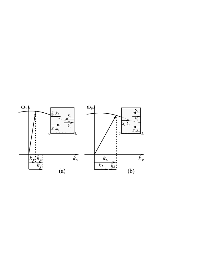
The dispersion curve for optical phonons is depicted in Fig. 1. It is negative in the range from zero to the boundary of the first Brillouin’s zone. Hence, the group velocity of such phonons, , is antiparallel with respect to its wave-vector, , and phase velocity, , because
| (1) |
Optical vibrations can be excited by the light waves due to the two-photon (Raman) scattering. The latter gives the ground to consider such a crystal as the analog of the medium with negative refractive index at the phonon frequency and to employ the processes of parametric interaction of three waves, two of which are ordinary EM waves and the third is the wave of elastic vibrations with the directions of the energy flow and of the wave-vector opposite to each other. For continuous wave SRS in the coupling geometry depicted in Fig. 1(a) and diamond crystal, estimates made in ph have shown that the minimum intensity of the fundamental field , required to reach the aforementioned extraordinary Raman amplification is on the order of W/cm2, which exceeds optical breakdown threshold. The main process that determines such a high intensity is fast phonon damping, which is characterized by the optical phonon relaxation rate on the order of s, and relatively small group velocity of the elastic oscillation cm/s for optical phonons with small optical wave vectors An ; Chen . Diamond is a representative of a wide class of transparent crystals which support optical phonons An ; Chen ; Card ; Alf ; Gor .
The goal of this work is to show that this seemingly formidable obstacle can be removed and the threshold intensity of the fundamental field required to realize such extraordinary coupling can be significantly reduced. It is possible by making use of short laser pulses with duration less then the lifetime of the vibrational oscillation of . Some of the properties of the output fundamental and Stokes pulses, such as duration and pulse shape are investigated.
II Equations and model
Consider lowest-order SRS process ShB ; Boy . The waves are given by equations
| (2) |
Here, , , and are the amplitudes, frequencies and wave-vectors of the fundamental, Stokes and vibrational waves; ; is displacement of the vibrating particles, is the medium density. With account for the frequency and phase matching exppressions,
one obtains following partial differential equations for the slowly varying amplitudes in the approximation of the of first order of in the polarization expansion Bl :
| (3) |
Here, are the projections of the group velocities of the fundamental, Stokes and vibration waves on the z-axis, is the number density of the vibrating molecules, is the molecule polarizability, is the mean free path of phonons.
For the sake of simplicity, we consider model of a rectangular pulse of input fundamental radiation with duration much shorter that the phonon lifetime . In the coordinate frame associated with this pulse and within the fundamental pulse range, complex amplitudes of two other interacting fields become time independent, and Eqs. (II) transform into set of ordinary differential equations whose solution is known in the approximation of constant pump amplitude or can be relatively easily found numerically when depletion of the pump is accounted for. Here, the boundary conditions must be fulfilled not at the boundaries of the medium but at the boundaries of the fundamental pulse. The latter is correct for the period of time after the instant when generated waves reach the boundaries of the fundamental pulse due to the difference in their group velocities or direction of propagation. Such approximation becomes true after travailing a distance , where . Here, , which is further referred to as group length, is defined as
| (4) |
where are negative if their energy fluxes are opposite to that of the fundamental wave. Hereinafter, the waves are referred to as co-propagating waves if Poynting vector of the Stokes wave is co-directed with that of fundamental wave (Fig. 1a), and as counter-propagating in the opposite case (Fig. 1b). In the approximation of constant pump amplitude, in the coordinate frame locked to the pump pulse and within the pulse, equations for generated Stokes and backward vibration waves take the form:
| (5) |
where , , . Here, intensity of the laser beam is taken constant. Depletion of the fundamental beam is neglected. Equations (II) may describe significant amplification of the Stokes signal, however they remain valid until only relatively small part of the strong input laser beam is converted. Equations (II) do not depend on time and are similar to those describing CW TWM ph . Here, group velocities , and wave vector for co-propagating and , for counter-propagating phase matching configurations. Since the Stokes frequency is less than that of the fundamental one, and is much greater than the magnitude of phonon group velocity .In the case of co-directed laser and Stokes waves, the boundary conditions take the form:
| (6) |
In the opposite case of counter-propagating Stokes and laser waves, the boundary conditions are given by equations
| (7) |
Here, is length of the fundamental pulse.
Solution to Eqs. (II) can be presented in the form:
| (8) | |||||
Here, and are transparency (amplification) factors, , , , , , , , .
For , phonon damping can be neglected and Eqs. (8) take the form
| (9) |
III Enhancing coherent energy transfer between electromagnetic waves through backward optical phonons
In the given approximation of neglected depletion of the fundamental wave, solution to Eq. (II) tends to infinity for certain pulse length and intensity. This indicates the possibility to greatly enhance the conversion efficiency provided that the following requirements are met:
| (10) |
Corresponding threshold intensity of the fundamental field , which is required for realization of great enhancement of energy conversion due to NLO coupling with BW phonon, is given by equations:
| (11) |
Here, is refractive index at Stokes frequency, is Stokes wavelength in the vacuum.
III.1 Factors discriminating BW SRS in continuous wave and pulsed regimes
Threshold intensity of fundamental radiation required for realization of BW SRS in CW regime is given by ph
| (12) |
It differs from the threshold value in pulse regime by factor
| (13) |
For the same typical crystal parameters as employed in ph , Eq. (13) yields . Hence, decreases down to W/cm2, which is achievable with commercial femtosecond lasers and falls below optical breakdown threshold for most transparent crystals.
Equation (13) displays two factors that determine substantial decrease of in pulsed regime compared to that in CW one. First factor is the ratio of group velocity of the elastic wave to that of the fundamental one, , which is on the order of . This factor is attributed to the fact that phonons generated on the front edge of the laser pulse propagate in the opposite direction and, hence, exit very fast, practically with the optical group velocity, from the fundamental pulse zone before it is dissipated. Hence, effective phonon mean free pass becomes commensurable with the fundamental pulse length. This mitigates the detrimental effect of phonon damping. With increase of , phonon mean free path grows, which decreases both and in a way that the advantage of pulse regime over CW regime diminishes. The second factor in Eq. (13) determines further decrease of due to small optical dispersion in the transparency region of the crystals. The fact that the Stokes pulse surpasses the fundamental one slowly increases significantly the effective NLO coupling length.
III.2 Numerical simulations, .
Numerical analysis is done for the model with parameters typical for diamond crystal An ; Chen : carrying wavelength of the fundamental pulse nm, pulse duration fs, cm-1, vibrational transition width cm-1, cm/s, cm/s, cm/s for co-propagating and cm/s for counter-propagating waves, (g/cm)1/2. Partial differential equations (II) were solved numerically in three steps: TWM in the vicinity of the entrance to the Raman medium, TWM and propagation through the medium and TWM in the vicinity of the exit from the Raman slab. Numerical simulation for the first and third medium intervals were made in the laboratory reference frame with the boundary conditions applied to the corresponding edges of the slab. NLO propagation process inside the slab was simulated in the moving frame of reference with the boundary conditions applied to the pulse edges. Such a computing approach allows for significant reduction of the computation time since, for each given instant, integration is required only through a space interval covered by the fundamental pulse and not through the entire medium. Shape of the fundamental pulse was chosen nearly rectangular and symmetric with respect to its center
the slope , the pulse duration at half-maximum and pulse delay were scaled to the fundamental pulse width . The amplitude of input CW Stokes signal was chosen .
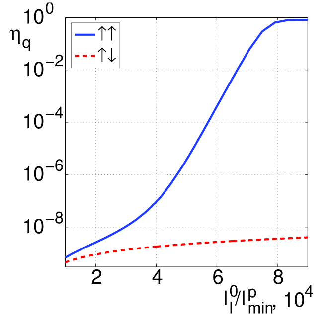
Figure 2 displays output quantum conversion efficiency vs. input pulse intensity (the same as vs. input pulse energy) both for co-propagating () and counter-propagating () geometries. A great increase of the conversion efficiency due to BW effect in the case of co-propagating waves is explicitly seen. Saturation at is due to depletion of fundamental radiation caused by conversion to Stokes radiation.
(a)
(b)
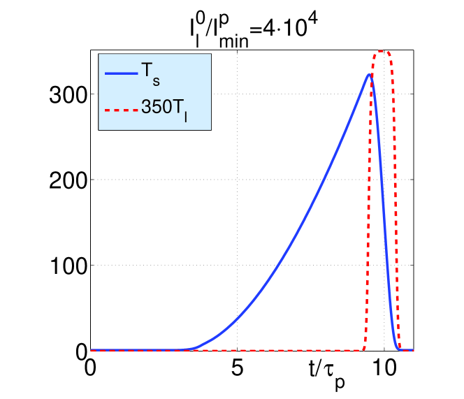
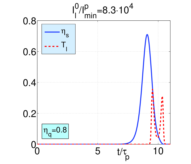
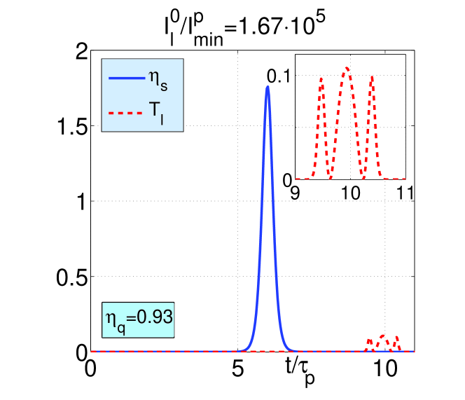
Simulations also show that shape of the output Stokes and fundamental pulses differ and vary significantly depending on the intensity of the input fundamental wave. Input seeding signal at Stokes frequency is assumed a weak CW broadband radiation. Figure 3 depicts amplified output pulse of Stokes radiation for relatively small amplification of the signal and small depletion of the fundamental beam. Here, shape of the fundamental pulse remains unchanged. Pulse shape of amplified Stokes signal is different and determined by the fact that and Stokes pulse surpasses fundamental one. In contrast, at and (Figs. 4a,b), conversion efficiency becomes significant ( 0.8 and , respectively). Corresponding depletion of the output fundamental pulse and changes in its shape is explicitly seen. Note that in the case shown in Fig. 4(b), the output Stokes pulse significantly overtakes the pump pulse. In the latter case, major conversion occurs in the middle of the medium, after which both pulses propagate almost without interacting and independently from each other. It is seen that output Stokes pulse narrows with increase of the input fundamental intensity. Here, crystal length of 1cm corresponds to more than 1000 input pulse lengths ( = 1357). Threshold intensity W/cm2, which corresponds to 60 fs pulse of 5 J focused to the spot of diameter D = 100 m. Intensity of seeding Stokes signal was chosen .
Described NLO propagation processes are in striking contrast with their counterparts in crystals where only phonons with positive group velocity exist ShB ; Boy . Such NLO properties are also different from those inherent to phase-matched mixing of EM and acoustic waves for the cases where the latter have energy flux and wave vector directed against EM waves Bob . Elaboration of the proposed concept allows to utilize revealed extraordinary features for creation of a family of unique photonic devices made of ordinary Raman crystals such as optical switches, filters, amplifiers and cavity-free optical parametric oscillators. Proposed here concept is different from earlier proposed in Har and does not require periodic poling of quadratic nonlinear susceptibility of crystals at the nanoscale as described in Kh (and references therein).
IV Conclusions
While the physics and applications of NIMs are being explored world-wide at a rapid pace, current mainstream focuses on fabrication of specially shaped nanostructures which enable negative optical magnetism. It is challenging task that relies on sophisticated methods of nanotechnology. Engineering a strong fast quadratic NLO response by such mesoatoms also presents a challenging goal not yet achieved. This paper proposes to mimic similar extraordinary backward-wave extraordinary nonlinear-optical propagation processes, however, making use readily available Raman active crystals. Among the prospective application is a family of photonic devices with advanced functional properties. Basic underpinning idea is to replace one of the coupled backward electromagnetic wave by optical phonons - elastic waves with negative group velocity.Operation in short pulse regime is proposed to remove such a severe detrimental factor as fast phonon damping. Significant decrease of the required minimum intensity of fundamental radiation compared with that in continuous-wave regime is shown down to that provided by commercial lasers. Unusual properties of the investigated processes are numerically simulated and the possibilities of pulse shape tailoring are predicted. There are many Raman active transparent crystals that support optical phonons with negative group velocity can be utilized, some of them, such as calcite, may offer further optimization of operational characteristics of the proposed photonic devices.
Acknowledgements.
This work was supported in parts by the Air Force Office of Scientific Research (Contract No FA950-12-1-298), by the National Science Foundation (Grant No ECCS-1028353), by the Academy of Finland and Nokia through the Center-of- Excellence program, by the Presidium of the Russian Academy of Sciences (Grant No 24-31), and by the Russian Federal Program on Science, Education and In- novation ( Grant No 14.A18.21.1942).References
- (1) A. K. Popov and V. M. Shalaev, Negative-index metamaterials: second-harmonic generation, Manley Rowe relations and parametric amplification, Appl. Phys. B: Lasers and Optics 84: 131–137, 2006.
- (2) A. K. Popov and V. M. Shalaev, Compensating losses in negative-index metamaterials by optical parametric amplification, Opt. Lett. 31: 2169–2171, 2006.
- (3) A. K. Popov, S. A. Myslivets, T. F. George, and V. M. Shalaev, Four–wave mixing, quantum control, and compensating losses in doped negative-index photonic metamaterials,” Opt. Lett. 32: 3044–3046, 2007.
- (4) A. K. Popov and S. A. Myslivets, Transformable broad-band transparency and amplification in negative-index films, Appl. Phys. Lett. 93: 191117(3), 2008.
- (5) A. K. Popov, S. A. Myslivets, and V. M. Shalaev, Resonant nonlinear optics of backward waves in negative-index metamaterials, Appl. Phys. B: Lasers and Optics 96: 315–323, 2009.
- (6) A. K. Popov, S. A. Myslivets, and V. M. Shalaev, Microscopic mirrorless negative-index optical parametric oscillator, Opt. Lett. 34: 1165–1167, 2009.
- (7) A. K. Popov, S. A. Myslivets and V.M. Shalaev, Plasmonics: nonlinear optics, negative phase and transformable transparency (Invited Paper), in Plasmonics: Nanoimaging, Nanofabrication, and their Applications V, edited by Satoshi Kawata, Vladimir M. Shalaev, Din Ping Tsai, Proc. SPIE 7395: 73950Z-1(12), 2009.
- (8) A. K. Popov, S. A. Myslivets, and V. M. Shalaev, Coherent nonlinear optics and quantum control in negative-index metamaterials, J. Opt. A: Pure Appl. Opt. 11: 114028(13), 2009.
- (9) A. K. Popov and S. A. Myslivets, Numerical Simulations of Negative-Index Nanocomposites and Backward-Wave Photonic Microdevices, ”ICMS 2010 : International Conference on Modeling and Simulation,” Proc. of WASET 37: 107–121 2010; http://www.waset.org/journals/waset/v37/v37-16.pdf .
- (10) A. K. Popov and T. F. George, Computational studies of tailored negative-index metamaterials and microdevices, a chapter in Computational Studies of New Materials II: From Ultrafast Processes and Nanostructures to Optoelectronics, Energy Storage and Nanomedicine, Edited by T. F. George, D. Jelski, R. R. Letfullin, and G. Zhang, World Scientific, Singapore, 2011.
- (11) A. K. Popov, Nonlinear optics of backward waves and extraordinary features of plasmonic nonlinear-optical microdevices, Eur. Phys. J. D 58: 263–274, 2010 (topical issue on Laser Dynamics and Nonlinear Photonics).
- (12) A. K. Popov and V. M. Shalaev, ”Merging nonlinear optics and negative-index metamaterials,” Proc. SPIE 8093-06: 1–27, 2011; arXiv:1108.0867.
- (13) I. V. Shadrivov, A. A. Zharov, and Yu. S. Kivshar, Second-Harmonic Generation in Nonlinear Left-Handed Metamaterials, J. Opt. Soc. Am. B23: 529–534, 2006.
- (14) M. Scalora, G. D’Aguanno, M. Bloemer, M. Centini, N. Mattiucci, D. de Ceglia and Yu. S. Kivshar, Dynamics of Short Pulses and Phase Matched Second Harmonic Generation in Negative Index Materials, Opt. Express, 14: 4746–4756, 2006.
- (15) A. K. Popov, V. V. Slabko, and V. M. Shalaev, Second harmonic generation in left-handed metamaterials, Laser Phys. Lett. 3: 293–296, 2006.
- (16) A. I. Maimistov and I. R. Gabitov, E. V. Kazantseva, Quadratic solitons in media with negative refractive index, Opt. Spectrosc. 102, 90–97 2007.
- (17) A. I. Maimistov and I. R. Gabitov, Nonlinear optical effects in artificial materials, Eur. Phys. J. Special Topics 147: 265 286, 2007
- (18) S. O. Elyutin, A. I. Maimistov, and I. R. Gabitov, On the third harmonic generation in a medium with negative pump wave refraction, JETP 111: 157–169, 2010.
- (19) M. I. Shalaev, S. A. Myslivets, V. V. Slabko and A. K. Popov, ”Negative group velocity and three-wave mixing in dielectric crystals, Optics Lett. 36: 3861–3863, 2011.
- (20) L. I. Mandelstam, Group velocity in a crystall lattice, ZhETF 15: 475–478, 1945 (in Russian).
- (21) E. Anastassakis, S. Iwasa and E. Burstein, Electric-Field-Induced Infrared Absorption In Diamond, Phys. Rev. Lett. 17: 1051–1054, 1966.
- (22) Y. Chen and J. D. Lee, Determining material constants in micromorphic theory through phonon dispersion relations, Int. J. of Engineering Sci. 41: 871–886, 2003.
- (23) Light Scattering in Solids, Ed.M. Cardona, Ch.2 in Topics in Applied Physics, vol. 8, Springer-Verlag, Berlin, Heidelderg, NY, 1975.
- (24) R. R. Alfano and S. I. Shapiro, Optical Phonon Lifetime Measured Directly with Picosecond Pulses, Phys. Rev. Lett. 26: 1247–1251, 1971.
- (25) V. S. Gorelik, Contemporary problems of Raman spectroscopy, Moscow, Nauka Publishing Co., 1978 in Russian), pp. 28–47.
- (26) Y. R. Shen and N. Bloembergen, Theory of stimulated brillouin and raman scattering, Phys. Rev. 137: A1787-A1805, 1965.
- (27) R. W. Boyd, Nonlinear Optics, Third Edition (Amsterdam: Academic Press, 2008.
- (28) Bloembergen, N., [Nonlinear Optics], W. A. Benjamin, Inc., New York, 1965, Ch. 4.
- (29) D. L. Bobroff, Coupled-modes analysis of the phonon-photon parametric backward-wave oscillator, J. Appl. Phys. 36: 1760–1769, 1965.
- (30) S. E. Harris, Proposed backward wave oscillations in the infrared, Appl. Phys. Lett. 9: 114–117, 1966.
- (31) J. B. Khurgin, Mirrorless magic, Nat. Photonics 1: 446–448, 2007 (and ref. therein).