Triple gear††thanks: This work is in the public domain.
Abstract
A relatively common sight in graphic designs is a planar arrangement of three gears in contact. However, since neighboring gears must rotate in opposite directions, none of the gears can move. We give a non-planar, and non-frozen, arrangement of three linked gears.
1 Introduction
2pt
\pinlabelmeridian [Br] at 185 407
\pinlabellongitude [tr] at 10 190
\pinlabel curve at 310 160
\endlabellist
The mathematician’s torus is simply the crust of a bagel: a surface with one hole. There are two special kinds of curves on the torus called meridians and longitudes. These are the curves obtained by slicing the bagel vertically or horizontally, respectively. We call a curve on the torus a curve if it crosses a longitude times and a meridian times. See Figure 1.
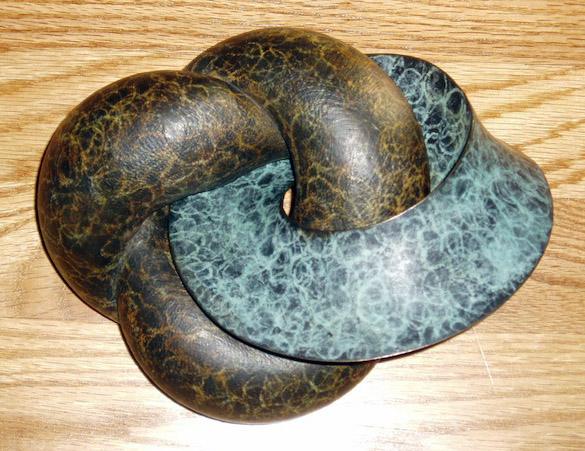
Helaman Ferguson’s Umbilic Torus NC is a classic work of mathematical art; topologically it is a torus with a ridge along a curve [4]. He has also designed a complementary sculpture, called the Umbilic Torus NIST; here we find a torus with a valley along a curve. These complementary tori are mated in his piece Umbilic Rolling Link, see Figure 2. Note that the ridge of the NC torus meshes with the valley of the NIST torus. Thus if one of the tori rotates along itself then so must the other, with speeds in a ratio of .
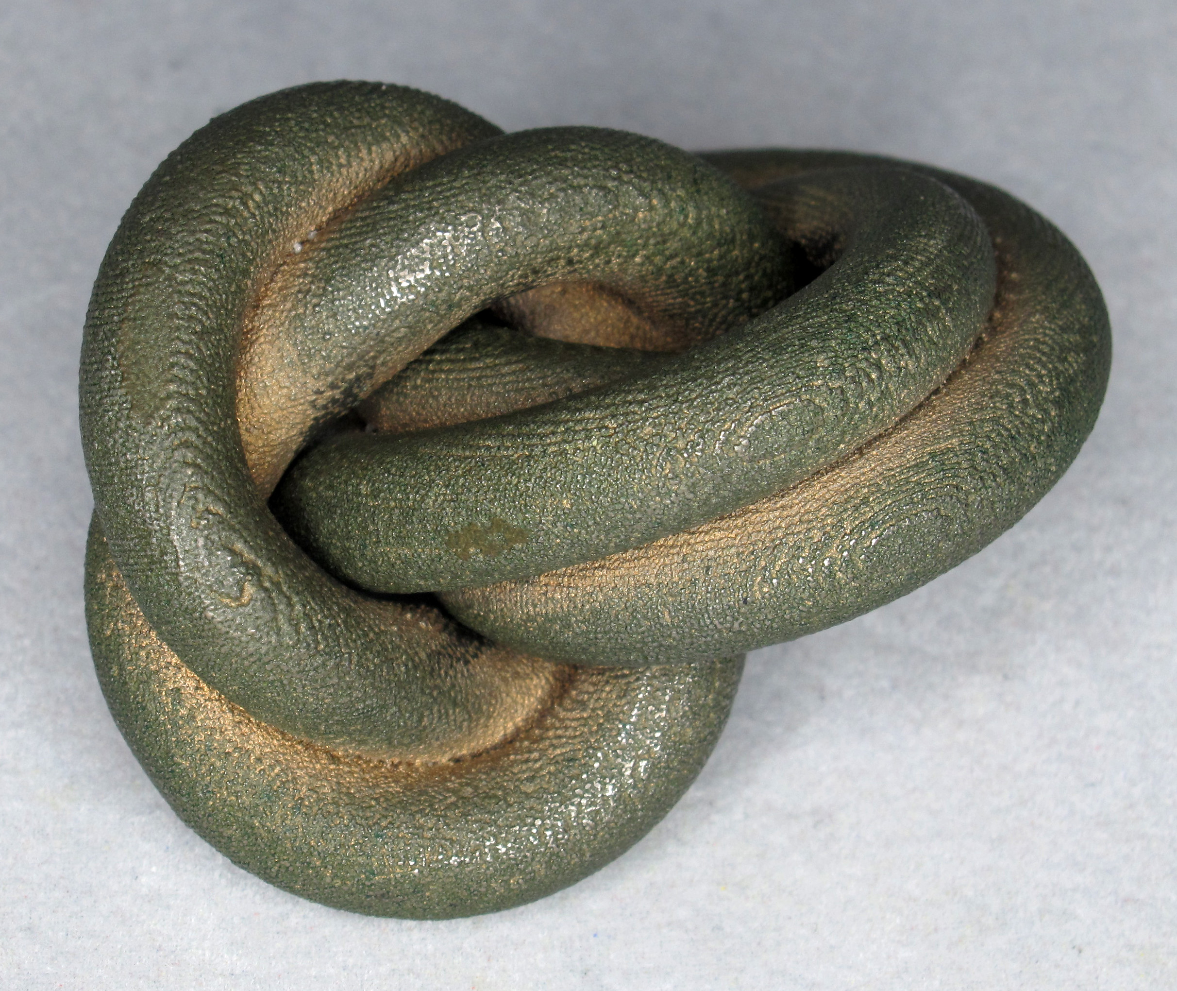
A closely related piece by Oskar van Deventer inspired this project. His Knotted Gear111See http://www.youtube.com/watch?v=ZqiHHlE1SD8 for a video of the knotted gear in motion. consist of two rings, a thickened curve (a left-handed trefoil) linked with a thickened curve. See Figure 3. The two rings mesh with speeds in a ratio of . We quickly decided that by varying and any rational ratio could, in principle, be achieved. We next asked “Can this be done with three or more rings?”
To formalize this problem we begin with some examples and definitions. An example of a rigid body is a wheel. An example of a rigid motion is a rotation of the wheel about its center through some angle. A movement is a one-parameter family of rigid motions . For example, consider spinning the wheel about its center with constant angular velocity : then at time , the motion is a rotation through degrees. Given two motions and , the composition of with , denoted , is the motion we get by performing followed by . A movement is simple if for any times and we have . Note that the simple movements are either stationary, translational, rotational or screw movement. These movements get their name from the classical simple machines: the lever, the wheel, the screw, and so on. For example, the spinning wheel is a simple movement.
Next, a design is a union of rigid bodies in space, with disjoint interiors. As an example of a design, we may take a wheel on an axle as shown in Figure 4. We add two flanges to the axle to stop the wheel from moving along the length of the axle.
A compound movement , of , is a collection of movements, one for each rigid body, which together keep the interiors of the bodies disjoint. In the example, spin the wheel in one direction while spinning the axle in the other. As this happens we may additionally translate both through space to give a new compound movement. In other words, if is a compound movement of and is any movement then we define a new compound movement by composing all of the movements of with , moment by moment.
Two compound movements and are equivalent if there is a movement so that . Thus, the two compound movements of wheel plus axle discussed above are equivalent.
We now restrict the degrees of freedom of via the following axiom.
-
Tracked: There is a compound movement of so that every compound movement of is equivalent to a time-reparameterization of .
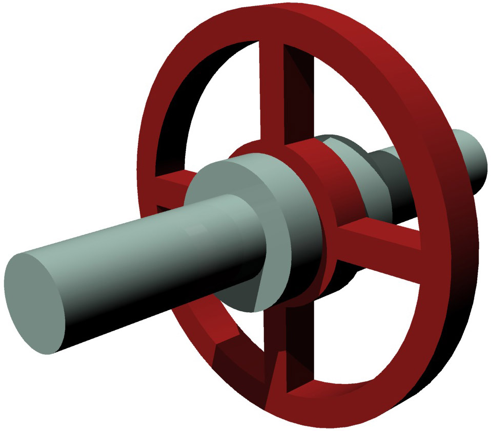
The wheel plus axle satisfies tracked: we can rotate the wheel on the axle and there is essentially no other way that they can move relative to each other. However, an axle with two wheels (again with flanges holding them in place) does not satisfy tracked. This axiom implies that in , as in many geared machines, the bodies may move relative to each other in an essentially unique fashion. We now distinguish the wheel and axle from the designs of Ferguson and Van Deventer.
-
Epicyclic: For any bodies and in the design , if and are in contact at some moment then the given movement of , in the frame of reference of , is not simple.
Fixing the axle pointwise, the wheel can only spin about its center, which is a simple movement. Hence the wheel plus axle is not epicyclic. Note that in ordinary mechanisms, the parts in contact with the gear-box have simple movements, in the frame of reference of the box. Such mechanisms are not epicyclic. In view of this axiom we will refer to all of the rigid bodies in our design as gears.
To simplify our search for a tracked, epicyclic three-component design, we add the following axiom.
-
Symmetry: Any gear of may be taken to any other by a rigid motion preserving .
To ensure that is tracked, we will make a series of assumptions, at each stage reducing the possible compound movements of the design. To ensure that is epicyclic we must do this without using any kind of framework or gear-box, following Ferguson and Van Deventer. Departing from their work, symmetry implies that all of our gears must be identical.
2 Topology
In this section we prevent compound movements that move the gears arbitrarily far from each other. We first assume that each gear is a circular ring. Now, if no pair of rings is linked, then is globally unlinked [5, Lemma 3.2]. Thus we assume that some pair of rings is linked. For example, this rules out the Borromean rings.

As suggested above, we further restrict our attention to designs with only three rings. The symmetry condition now implies that all three pairs of rings are linked. A geometric argument given in Appendix B proves the design is, topologically, the three-component Hopf link. Note that this rules out another natural candidate: the minimally twisted three chain link [6].
Examining cases, the symmetry axiom implies that there is a rigid motion, , that acts via an order three permutation222That is, if we apply three times then we are back to where we started. on the components of . It follows that is a rotation about a line in three-space of order three (i.e. by in one or the other direction). Our three-component Hopf link has just two symmetries of order three. Thus, we may assume that the rings of are equally spaced curves on a torus, as shown in Figure 5.
Consider the compound movement that rotates each of the rings about its center, all with the same speed and handedness. Note that preserves the design and obeys the symmetry axiom. Also, in the frame of reference of any one ring, the movements of the other two are not simple, so a design with this movement would be epicyclic. In the rest of the paper, we seek a shape for the individual rings that will satisfy the tracked axiom, using essentially this compound movement .
3 Maximal tori
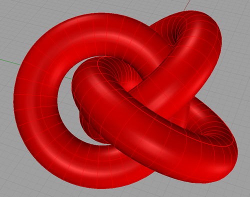
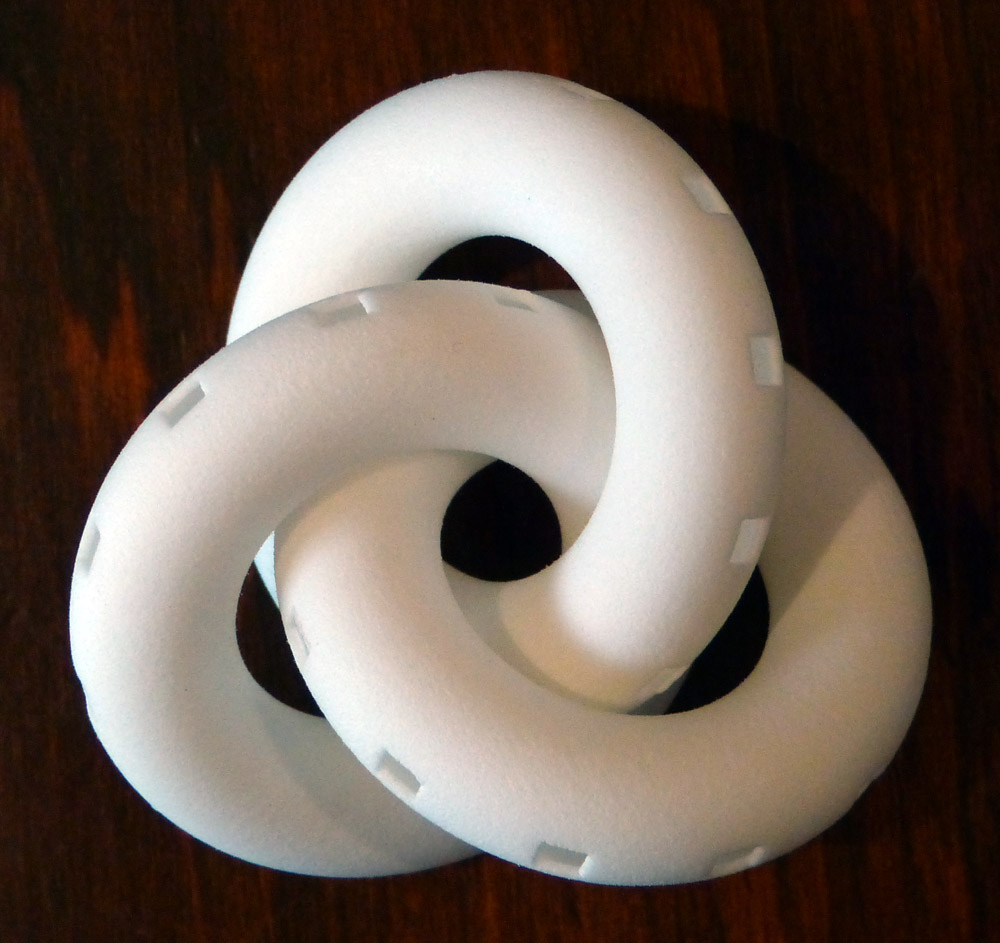
In any design satisfying the tracked axiom, the gears must remain in contact. To arrange this we take three congruent rings, linked as in Figure 5, and gradually increase their thickness; think of blowing up three tubular balloons. Their orientations may change as the rings bump each other, but we always maintain the –fold symmetry. Eventually the rings will reach some maximum thickness, giving an arrangement as in Figure 6a.
To find the positions of the rings at the maximal thickness we solve an optimization problem. The three circles, each of radius , are arranged so that rotation by around the –axis permutes them. We assume that one of the circles has center on the –axis, at distance from the origin. The plane containing this circle is spanned by the vectors and . These parameters are displayed in Figure 6b.
2pt \pinlabel at 129 94 \pinlabel at 170 140 \pinlabel at 105 193 \pinlabel at 253 112 \pinlabel at 8 200 \pinlabel at 83 243 \pinlabel at 96 82 \pinlabel at 115 150 \pinlabel at 183 123.5 \endlabellist

Our aim is to maximize the distance between this circle and one of its rotates, while preserving the topology. Note that there is no closed form for the minimal distance between two general circles [8]. Thus, a closed form solution for the optimal values of , , and seems unlikely. However, for our purposes a numerical approximation is good enough.
Ian Agol [1] points out that the optimal configuration should have dihedral symmetry, and thus . Here is the heuristic explanation. First, at the maximal thickness, each ring touches each of the other two in at least two points. This is because if there is only one point of contact, then the rings can be rotated to remove that point of contact and allow further thickening. Second, two linked congruent tori that are tangent to each other at two points should be related by a rotation of that exchanges the two points. This extra symmetry property seems to hold (although we do not know a proof) and implies the dihedral symmetry, which implies that .
We numerically obtain, for the other variables, values of and . At the maximum, the ring has thickness of and the distance between two core circles is twice this. We set up a coordinate system on the surface of each ring, a torus, as follows. Each torus is parameterized by . The parameter is in the longitude direction, with at the vector and nearest in the positive direction. The parameter is in the meridian direction, with at the biggest longitude (i.e. on the outside of the torus), and the direction closest in the positive direction. In these coordinates the points of contact of this torus with the others are at
Note there are two points of contact with each of the other tori. By symmetry, the same is true for the other two tori as well.
Some of the symmetries in these four points come from the dihedral symmetry of the configuration, but we currently do not know why the number appears both as a value for and for , nor why the sum of and appears to be .
If, at maximal thickness, the rings could move only along their core circles, then the symmetry axiom would completely determine the compound movement required by the tracked axiom. Unfortunately this is not the case: if we relax the –fold symmetry then we can further increase the thickness of the rings; see Figures 7a and 7b333We expect that maximizing the thickness of the rings in Figure 7b would restrict them to move only along their core circles. An interesting future direction is to explore gearing in this configuration..
4 Cutting teeth
We now add gear-teeth to the rings; this enforces the 3–fold rotational symmetry, preventing the configuration of Figure 7b. Recall that symmetry requires our rings to all rotate at the same speed.
For unlinked gears with parallel axes, the tracked axiom (implied by the fundamental law of gearing444The fundamental law of gearing states that the angular velocity ratio between two gears should remain constant as the gears rotate.) can be obtained using involutes of a circle for the shapes of the teeth; this was first proposed by Euler [2]. The version of this problem for skew axes is an area of active research. We looked in particular at work of Phillips [9, 10] on spatial involute gearing. We implemented his system, but ran into a serious problem. For any pair of axes, he gives a pair of surfaces that are tangent at the contact point and curve away from the contact point towards the two axes. This nicely suits the case when the gear lies on the side of the flank surface towards the axis, as in most applications. However, our gears link each other. Thus, it can happen that the gear may lie on the opposite side of Phillips’ tooth flank. It can even happen that the flank surfaces are roughly cylindrical, tangent at a point, curving in the same direction, and with different axes — in this case the two surfaces intersect in an ‘X’ shape.
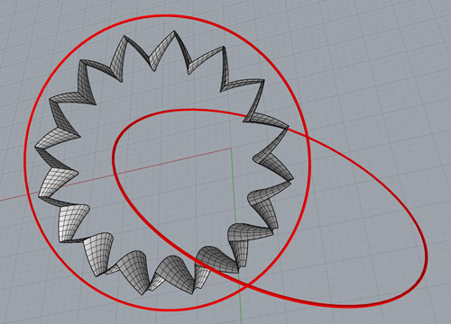
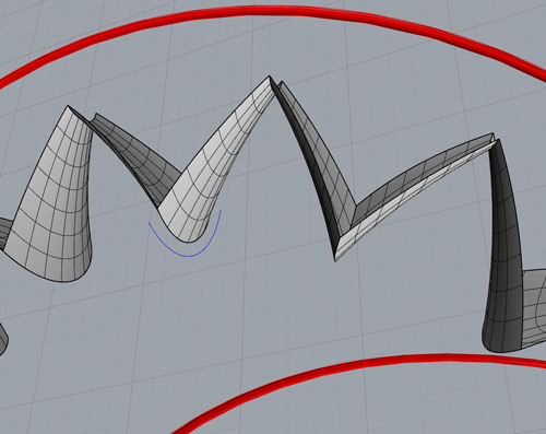
So we instead use an ad hoc method. We use one gear to carve the shape of the mating gear. In hindsight, our method is similar to techniques going back at least to 1896 [3, Figures 12–19]. Here are the details. We know the compound movement of the two meshing gears. We choose a point on the boundary of the first gear. We consider the path of in the frame of reference of the second gear. This path must be outside of, or on the boundary of, the second gear; so we imagine this path (and many other similar paths) carving the shape of the second gear, as if from a block of clay.
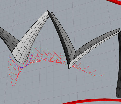
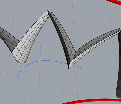
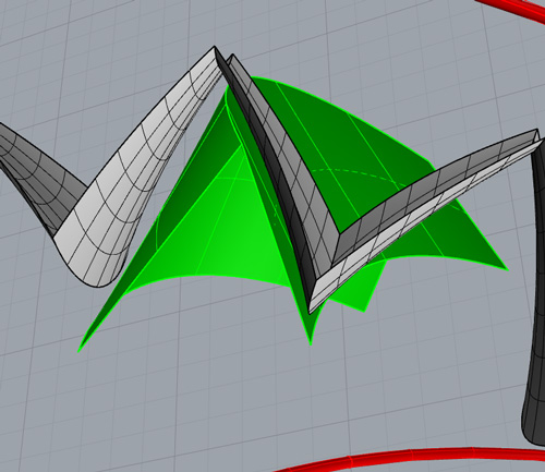
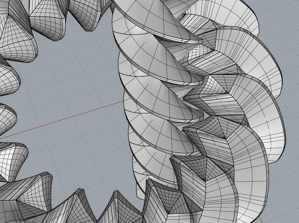
Note that this process transforms a point of one gear into a excluded path for the other gear; that is, the dimension increases by one. If we have a proposed –parameter tooth flank for the first gear, then this carves a –parameter volume in the frame of reference of the second gear. The appropriate tooth flank for the second gear would then be part of the boundary of that volume. In practice, we start with one set of gear teeth on the inside of one ring, and use it to carve a set of gear teeth for a second. See the steps outlined in Figure 8. The shapes of the first set of teeth are given by linear functions in the toroidal coordinates; the exact parameters were chosen with a fair amount of trial and error to work well with the carving process.
Note that the values of the points of contact on the torus determine longitudes of the torus that must have gearing on them. The two values and are very close to each other near the smallest longitude on the inside of the ring. These are so close that gear teeth from the other two rings intended to mesh with one longitude will most likely interfere with the other. For this reason, we merged these two longitudes into one gearing pattern, as seen in Figure 8a555The closeness of these two longitudes may cause problems in producing three gears that rotate at different speeds.. We follow the steps shown in Figure 8 to produce the tooth flanks. As is usual in gear design, we truncate to ensure a non-zero “top land” for the gear teeth. We transport the tooth flanks using the various symmetries of the design. The flanks are joined to each other with connecting patches, and the final closed surface is hollowed out; this allows recovery of unused material from the 3D printing process.
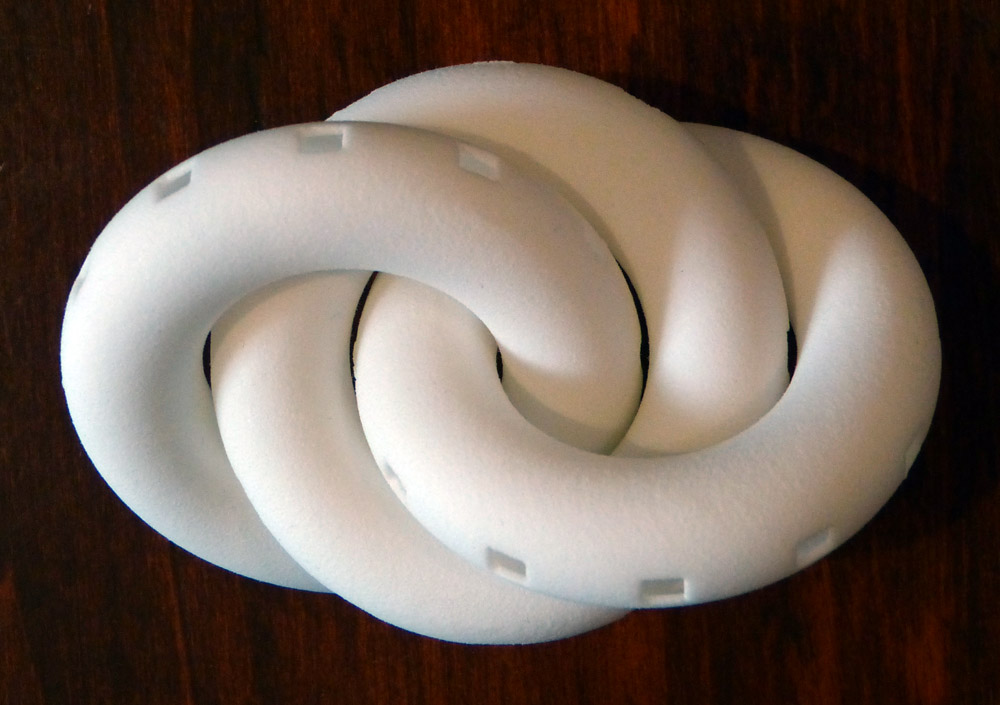
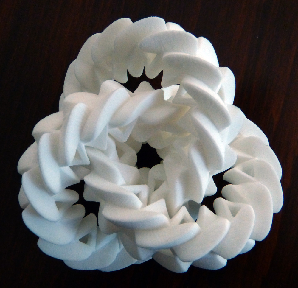
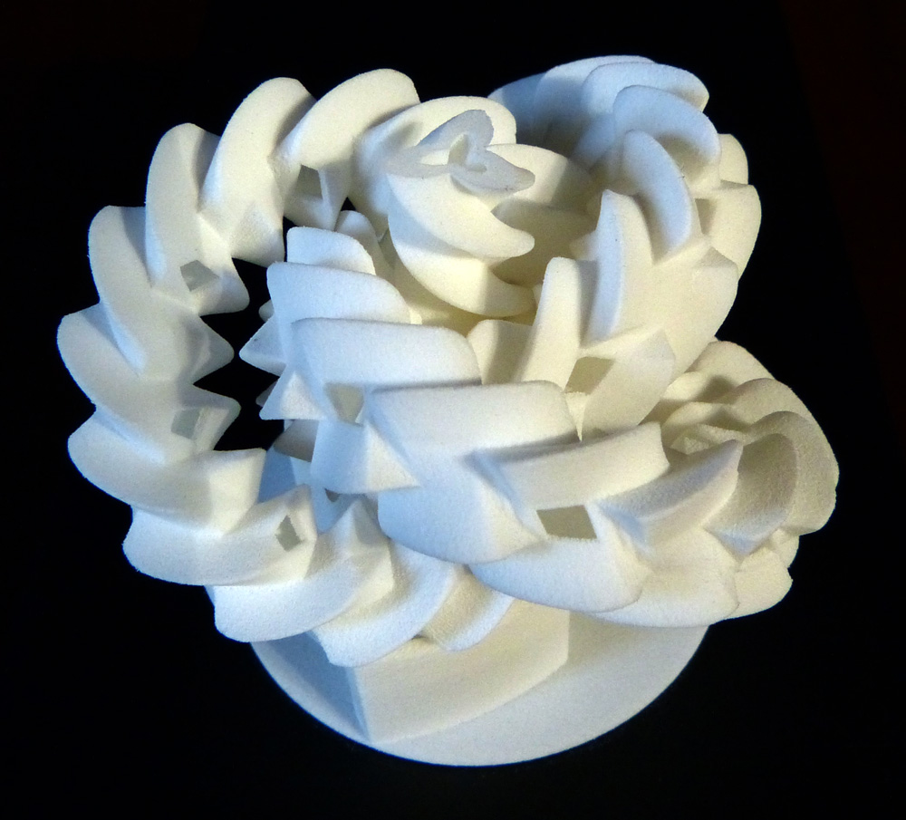
This completes our construction; Figure 8f displays the final result666See http://www.youtube.com/watch?v=I9IBQVHFeQs for a video of the triple gear in motion. It can be purchased at http://shpws.me/mQ6F. An STL file is available at http://www.thingiverse.com/thing:66708.. The gear teeth on each ring are arranged in three groups, one along the inside longitude of the ring and two along longitudes towards the outside of the ring. There are the same number of teeth on each of these, so in principle it might be possible to connect all of these together into a single twisting gearing pattern wrapping around the torus. This would have to be done very carefully, to avoid any unintended collisions between the added parts and the existing gear teeth.
The 3-fold symmetric three-component Hopf link is one of many other arrangements of linked circles that could lead to tracked, epicyclic designs. In addition to the configuration shown in Figure 7b, rotationally symmetric Hopf links with four or five components should be possible. We have also considered a design based on the minimally twisted six chain link [6], where neighboring rings are geared while rings two steps around the chain from each other are in contact but slide smoothly against each other.
5 Driving the triple gear
It is an interesting dexterity challenge to move the triple gear using your hands. Printed in PA 2200 nylon plastic by selective laser sintering, friction wins over weight; if you hold two of the gears and rotate them then the third is pushed out of the 3-fold symmetry position until the mechanism seizes. A finger positioned against the third gear stops it moving out of place; then the design moves as intended.
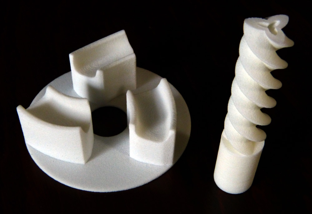
We have also designed a driving mechanism. As shown in Figure 9b, it consists of a central helical axle, powered by a motor, and a baseplate upon which the triple gear rests777See http://www.youtube.com/watch?v=QhXjevOY_uk for a video of the powered triple gear. We thank Adrian Goldwaser for initial prototyping and Stuart Young for further prototyping and construction of the motorized base. The baseplate and axle can be purchased at http://shpws.me/nIjE. An STL file is available at http://www.thingiverse.com/thing:78218.. The tooth cross-section for the helical axle is designed using essentially the same carving technique as in Section 4. Since the helix is invariant under a screw motion it can be inserted into the the triple gear without having to move the gears; it need not be printed in place.
The axle, with a rotational movement, can be added to the design with its original movement; this combination is again epicyclic. However, in reality this new design tends to prefer the compound movement where all of the circular gears are at rest with respect to the axle: that is, everything rotates about the axle at the same speed. This is definitely not epicyclic! The three cradles on the baseplate prevent this trivial compound motion.
Since rotational and translational movement of the helical axle are equivalent, we can also drive the triple gear by translating the axle through it. Thus we can place the triple gear at the top of a long axle and let it fall downwards under gravity. However, without the baseplate the triple gear only sometimes moves in the desired epicyclic fashion. It should be possible to produce a very large circular axle by gently bending the long axle into a ring. Holding the circular axle vertically and, pulling the axle hand-over-hand, the triple gear falls endlessly down the other side.
References
- [1] Ian Agol, Maximum thickness of three linked Euclidean solid tori, MathOverflow, http://mathoverflow.net/questions/83586 (version: 2011-12-17).
- [2] Leonhard Euler, Supplementum de figura dentium rotarum, Novi Commentarii academiae scientiarum imperialis Petropolitanae 11 (1767), 207–231.
- [3] Edwin R. Fellows, Gear-shaping machine, Patent (1896), US 579708, http://www.google.com/patents/US579708.
- [4] Helaman Ferguson and Claire Ferguson, Celebrating Mathematics in Stone and Bronze: Umbilic Torus NC vs SC, Proceedings of Bridges 2012, (2012) 17–24.
- [5] Michael H. Freedman and Richard Skora, Strange actions of groups on spheres, Journal of Differential Geometry 25 (1987), 75–98.
- [6] J. Kaiser and J. S. Purcell and C. Rollins, Volumes of chain links, http://arxiv.org/abs/1107.2865.
- [7] F. E. Lindsay, An interesting gear, The Engineer 135 (1923), 660, http://www.gracesguide.co.uk/images/c/cf/Er19230622.pdf.
- [8] C. Andrew Neff, Finding the distance between two circles in three-dimensional space, IBM Journal of Research and Development 34 (1990), no. 5, 770–775.
- [9] Jack Phillips, General spatial involute gearing, Springer, 2003.
- [10] Hellmuth Stachel, On Jack Phillip’s spatial involute gearing, The 11th International Conference on Geometry and Graphics, 1-5 August, 2004, Guangzhou, China.
Appendix A Postscript on paradoxes
After submission, but before publication, we stumbled across the work of Jacques Maurel888See http://www.jacquesmaurel.com/gears. His video http://www.youtube.com/watch?v=AwzL7Z_50zc inspired this appendix.. He explains, via many beautiful videos, Lindsay’s paradoxical gears [7]. We adapt these to find three gears with parallel axes, all in contact and all rotating in the same direction. However, these gears are not in fact planar; thus they narrowly avoid contradicting the second sentence of our abstract.

The three gear are helical screws, similar to the driving axle shown in Figure 9a. Their axes meet each horizontal plane at the vertices of an equilateral triangle. Each horizontal cross-section of each screw is an involute planar gear, as discussed in Section 4, but with only three teeth. See Figure 10 for a sequence of cross-sectional views. Descending, the cross-sections rotate, all in the same direction. Alternatively we can view the three pictures as an animation of a cross-section at a fixed height.
Note that in ordinary planar gearing, teeth of meshing gears meet close to the center line : the straight line between the gear centers. The normal to the teeth at the point of contact is roughly perpendicular to . Thus, using the cross-product to compute the torque on the follower, we find that the driver and follower rotate in opposite directions.
Consider the first cross-section of the paradoxical gears, shown in Figure 10. Again there is a triple of involute gears, in point contact. However, the point of contact of the upper two gears is much further from their center line, . At the point of contact the common normal to the teeth is parallel to . Thus the follower rotates in the same direction as the driver.
By the time we get to the third picture in the animation, the gears are no longer in contact. However, there are horizontal slices of the screws at other heights which have come into contact, reproducing the first picture. So the helical screws, as a whole, remain in contact and produce the desired paradoxical behavior.
Appendix B The three-component Hopf link
Theorem.
Let be a three-component link where every component is a round circle and every pair of circles is linked. Then is the three-component Hopf link.
Proof.
We work in . Let and be the – and –axes. After a Möbius transformation, we may assume that the first and second components of the link are the axes and . Let be the third component of and note that this is again a round circle.
Consider the set of great spheres that contain . Each such sphere is divided into two hemispheres by . Each sphere meets in two points, one in each hemisphere. So the set of hemispheres is indexed by the points of .
Since is round, and since it links , we deduce that intersects each great sphere containing in precisely two points, once in each hemisphere. Thus, as we go around , we hit every hemisphere in cyclic order. Similarly, as we go around , we hit the hemispheres in cyclic order. Note that is the geodesic segment from to , parameterized by for . We can deform by sliding each point along its respective geodesic segment until it is at . Thus becomes the curve on the torus . So , and are three fibers of the Hopf fibration of , and our link is the three-component Hopf link. ∎