Parabolic Strip Telescope
Abstract.
We present a proposal of a new type of telescopes using a rotating parabolic strip as the primary mirror. It is the most principal modification of the design of telescopes from the times of Galileo and Newton. In order to demonstrate the basic idea, the image of an artificial constellation observed by this kind of telescope was reconstructed using the techniques described in this article. As a working model of this new telescope, we have used an assembly of the primary mirror—a strip of acrylic glass parabolic mirror 40 cm long and 10 cm wide shaped as a parabolic cylinder of focal length 1 m—and an artificial constellation, a set of 5 apertures in a distance of 5 m illuminated from behind. In order to reconstruct the image, we made a series of snaps, each after a rotation of the constellation by 15 degrees. Using Matlab we reconstructed the image of the artificial constellation.
Keywords: Instrumentation: high angular resolution, Techniques: image processing, Telescopes.
1. Introduction
All known telescopic systems are of two basic types: the Galileo–Kepler using lenses (or lenses with corrections of optical defects) as primary optical elements (refractors), or the Newton–Cassegrain with spherical or paraboloid mirrors (reflectors) as the primary elements. The image is observed using photographic cameras, CCD cameras or a light spectrometers. The images from the CCD or the spectrometers are stored in computers for further elaboration. In all cases, the images are exposed in the image plane. The primary elements of the reflectors and of the refractors collect parallel rays of light in the focal plane, and other optical elements are used in different geometrical configurations. For more details see [1].
As a rule, telescopes are supported by mountings which make it possible to point their optical axes to the object to be observed. In the case of moving objects, the mounting makes the optical axis able to follow the position of the object. There are several types of mountings, the most important are parallactic, azimuthal, and four axes mountings. The azimuthal mounting has horizontal and vertical rotational axes, and it is necessary to perform both rotations simultaneously during the observation of moving objects. The parallactic mounting has two perpendicular axes, one axis is parallel to the Earth’s axis, and a suitable rotation around this axis makes the telescope follow the celestial objects. Most contemporary mountings are controlled by computers.
Up to now, telescopes have their primary elements of circular or regular polygonal form. The angular resolution of such telescopes is almost the same in all lateral directions, and it is defined as the smallest angle between two close points which can be distinguished. The angular resolution is the ability of a telescope to render detail: the higher resolution, the finer details can be observed. The angular resolution, together with the aperture size, are the two most important characteristics of telescopes. In the case of circular primary mirror of diameter , its area and angular resolution are
for a monochromatic light of wavelength [2].
There are two reasons for the construction of very large telescopes: to gain better angular resolution and to collect more light [3]. In those cases improving the resolution and collecting more light means increasing the diameter of the primary mirror.
2. Telescope with a rotating objective element
The basic idea of our new system has been inspired by X-ray computer tomography (CT). An X-ray source is located on one side and an X-ray camera on the opposite side of a sample. The integral absorptions of X-rays in different angles step by step during the rotation of the sample are measured. The total absorption of all photons coming along different lines perpendicular to the camera are registered as points of a one-dimensional picture. Finally, the inverse Radon transform is used to reconstruct the image of absorption of X-rays in different points of the media.
Modern mathematical methods and software developed for CT involve gathering projection data from multiple directions and feeding the data into a tomographic reconstruction software algorithm processed by a computer [3]. Mathematical filters are used to improve the reconstructed image [4]. The idea and the image processing of the technology of Single-Photon Emission Computer Tomography (English 1996) is the same as for our parabolic strip telescope. This technology is used in nuclear medicine where a patient is injected with a radiopharmaceutic which emits gamma rays. The emitted gamma rays are collected by a gamma camera and the emitted image is reconstructed [7].
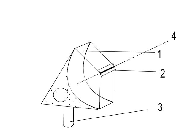
The same approach can be used when a parabolic strip is the primary mirror (h, i) of a telescope, following the schematic shown in Figure 1. The images of observed objects are lines. Each line represents the integral intensity of light incoming from the object or objects perpendicular to the strip (parallel to the focal line) located inside the field of view which is guaranteed by the geometry. Making a series of photos while rotating the telescope around its optical axis, one can use the inverse Radon transform to reconstruct the image with the above mentioned angular resolution. It is also possible to use other tools, for example Matlab [7]. Secondary optic elements can be used to focus the lines from the focal plane into points.
The technological construction of the parabolic strip is simpler than planar or paraboloid surface, because the stress of material helps to maintain the geometry. A precise parabolic bracket is required to hold the parabolic strip made of elastic mirrors. It is also simpler to use adaptive optics for the correction of defects. One can control the surface by a laser pointer located on one side of the strip. By the detection of its reflected light on the other side of the strip during the scan, the whole surface can be controlled and corrected by corrective elements. Of course, secondary mirrors can be added, then we have a Newton–like or Cassegrain–like telescope. The area and the angular resolution of a parabolic strip telescope are
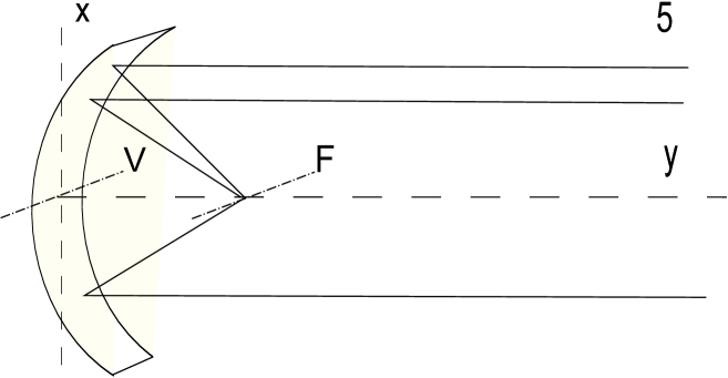
where is the wavelength of light, is the length of projection of strip on tangent plane at the vertex line—in Figure 2 it is the length of x-axis projection of the strip—and is the width of the strip.
The proposed telescopic system involves preferably parallactic mounting and an instrument for the digitalization of the image connected to a computer.
The mounting, however, has to perform one more rotation than the usual mounting: a rotation of the primary element or of the whole system around the optical axis is necessary, in order to reconstruct the details of the object. The instrument for the digitalization of images has to be located in the image plane of the telescope.
For refractors the new primary elements are cuts of parabolic cylinders and instruments for the digitalization of the image are located in the image plane of the telescopes. Of course, this idea can also be used for radio telescopes.
3. Advantages
We have proposed a fundamental modification of reflectors where the angular resolution can be better than in the case of usual objectives of the same area. The reconstruction of images exploits the discrete inverse Radon transform [6] or similar mathematical methods. The main advantages of such telescopes are
-
•
good angular resolution,
-
•
low expenses,
-
•
simple technological development,
-
•
possibility to install a grid of large telescopes across the Earth,
-
•
lower weight for use on satellites.
The only major complication is that one more rotational movement is needed to reconstruct the image with the same angular resolution in all directions.
The good angular resolution can be used for direct observation of bright objects. The additive rotation is not necessary for some purpose, for example when the plane of rotation of rotating objects is known, and changes of orbits are observed. For example, the Jupiter-like planet around close stars can be directly detectable by a 60 meter telescope, from point of view of the requirement angular resolution.
The relatively low cost of parabolic strip telescopes makes it possible to cover the Earth from North to South by a grid of telescopes. Each of them would observe, for example, 30 degrees around the zenith. This would reduce the cost of mountings and multiply the observation time. The cost of telescopes observing 15 degrees will be reduced because of:
-
•
high mounting not being necessary,
-
•
low wind influence,
-
•
low gravitational influence.
4. Secondary optics
The parabolic strip telescope offers the possibility to use secondary optical elements to focus light from the primary mirror to short segments or points. But these secondary elements may introduce errors or noise in resulting images. The most natural and easiest way is to use a "software" secondary element, i.e. a computer process on images created by the primary mirror. This can be explained on the following simple example. Let us observe two distinguishable objects lying on a line parallel to the vertex line. The points represent objects whose structure is below the angular resolution of a telescope in that direction. The image of each object is a segment of length W that is parallel with the vertex line, and both segments lie on the same straight line. The centers of the segments are located symmetrically to the optical axis in directions according to the reflection law. Depending on the strip width W and the angle between the two objects, the two segments are either separated or overlapping. If the segments are separated, their images are placed in the centers of the segments. If the segments are overlapping, then a simple analysis gives the position of images of the objects. One has to subtract the half width of the parabolic strip from one end of the overlapping segments and from the opposite end of the overlapping segments, and these are the positions of objects on the image. In Figure 5 the end points of displaced segments are shown. The segments are images of the artificial constellation. Angular resolution in determining the position of a point in the direction of the vertex line is and is substantially less than in the perpendicular direction . This difference in angular resolution in two perpendicular directions can serve for observation of some particular phenomena. For example, to monitor fine movements of an object in the known direction, the telescope has to be adjusted so that in this direction the best angular resolution is achieved. During computer processing all the photons reflected from the primary mirror are recorded by pixels of a CCD camera in the image plane and no one is lost. Using a secondary parabolic strip or a secondary parabolic lens from the Hartley disc, the segments can be focused into points. Then the inverse Radon transform reconstruct the image with appropriate angular resolutions.
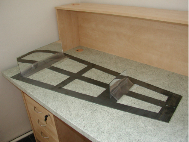
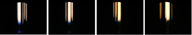
5. The proof-of-principle experiment
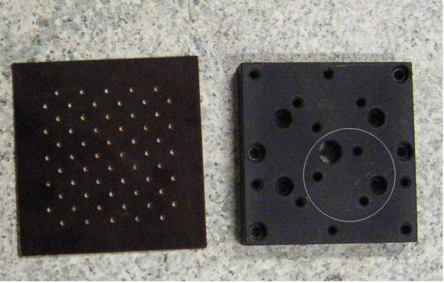
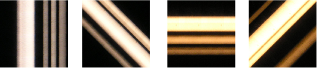
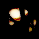
In order to show that the principle works we have prepared a very basic experiment. For the sake of simplification, the telescope was stationary. Figure 3 shows manufactured parabolic strips of lengths 20 and 40 cm. In the experiment the 40 cm strip was used. The artificial constellation was represented by a light shining through five apertures. The artificial constellations used are shown in Figure 4. The constellation was then rotated in steps of 15 degrees and the images were photographed by an ordinary digital camera. Figure 5 shows four photos for the constellation at angles 0, 45, 90 and 135 degrees. Figure 6 shows the same photos after two steps of processing—averaging and rotating. The reconstructed image is shown on Figure 7. For image processing, Matlab was used.
The principle of the telescope was successfully tested. The resulting image can be compared with the reconstructed images in [7]. With higher quality components and more measurements at finer angle steps, the reconstructed image would be of better quality.
Acknowledgements
The support by the Ministry of Education of Czech Republic project MSM6840770039 is acknowledged.
References
- [1] King H. C. 2003, The History of the Telescope, Dover Publication, New York
- [2] Crawford F.S. Jr. 1968, Berkeley Physics Course 3. Waves (McGraw-Hill Book Co., New York).
- [3] ESO 2012, The Very Large Telescope, https://www.eso.org/public/teles-instr/vlt.html
- [4] Herman, G. T. 2009, Fundamentals of computerized tomography: Image reconstruction from projection, 2nd ed., Springer,
- [5] Jahne, B. 1995, Digital Image Processing, Springer–Verlag
- [6] English, R. J.1996, Single–Photon Emission Computed Tomography: A Primer, Publ. of The Society of Nuclear Medicine,
- [7] Akram W., et al. 1996, Image Processing Using SPECT Analysis, (http://www.clear.rice.edu/elec431/projects96/DSP/index.html)
- [8] Chadzitaskos G., Tolar J. 2007, CZ Patent 298313
- [9] Chadzitaskos G., Tolar J. 2004, in Proc. SPIE. 5487, Optical, Infrared, and Millimeter Space Telescopes 1137 doi: 10.1117/12.5546007(arXiv: astro-ph/0310064)
- [10] Beylkin G. 1987, IEEE Transaction on Acoustics, Speech, and Signal processing, vol. ASSP-35, No. 2, 162