Compact surface Fano states embedded in the continuum of waveguide arrays
Wave localization at surfaces is a fundamental physical phenomenon with many important examples such as surface plasmon polaritons Boardman (1982); Maier (2007), Dyakonov surface modes D’yakonov (1988), and Tamm states Tamm (1932). Although being of different origin, these modes share the same property: they decay exponentially away from the surface, with the eigenfrequencies of the surface states being outside the band of the spatially extended propagating states. Here we describe theoretically and observe experimentally a novel type of surface states in a semi-infinite waveguide array with simultaneous Fano and Fabry-Perot resonances. We demonstrate that the Fano surface mode is compact, with all energy concentrated in a few waveguides at the edge and no field penetration beyond the side-coupled waveguide. We show that by broadening the spectral band in the rest of the waveguide array it is possible to suppress exponentially localized modes, whereas the Fano state having the eigenvalue embedded in the continuum is preserved.
Remarkably, in their seminal paper von Neumann and Wigner von Neumann and Wigner (1929) explicitly constructed a potential that supports so-called “bound states in the continuum” (BIC), i.e., a particular localized mode with the eigenfrequency inside the band of extended states. Since then, the peculiar concept of BIC attracted a lot of attention in various branches of physics Stillinger and Herrick (1975); Friedrich and Wintgen (1985), reaching a climax with the direct observation of an electronic bound state above a potential well due to Bragg reflection in semiconductor heterostructures Capasso et al. (1992). In the optical domain it was shown that BIC can be generated in photonic crystals and optical waveguide arrays Longhi (2007); Marinica et al. (2008); Bulgakov and Sadreev (2008); Dreisow et al. (2008); Longhi (2009); Bulgakov and Sadreev (2009); Otey et al. (2009); Bulgakov and Sadreev (2010). The first true observation of a BIC in any system was carried out in an optical system: a planar optical waveguide array with two side-coupled defects, in which an in-band defect state is formed by virtue of symmetry Plotnik et al. (2011). Recently, a special design of a one-dimensional (1D) waveguide array with modulated inter-site coupling was suggested in order to obtain “surface BIC” Molina et al. (2012).
The phenomenon of Fano resonance Fano (1961) provides a simple and universal means for obtaining bound states in the continuum, which can be realized in optics through the addition of side-coupled waveguides or cavities Miroshnichenko et al. (2010). Indeed, at Fano resonance there appears an effectively infinite potential barrier such that an incident wave exhibits complete reflection, and such mechanism is responsible for light trapping studied in photonic crystal waveguides between two side coupled defects Pan et al. (2008, 2010a, 2010b), at a cavity placed near the waveguide termination Tanaka et al. (2007), and predicted for waveguide arrays with side-coupled waveguides Longhi (2007). In this regime the mode can be trapped even when its eigenvalue is embedded in a continuum spectrum of the optical waveguide.
In this Letter, we present the theoretical analysis and the experimental observation of the formation of surface Fano states. To this end, we employ an optical system: an array of evanescently coupled waveguides with a side coupled waveguide close to the lattice edge. We show that the Fano modes are “compact”, i.e., there is no wave penetration beyond the location of the side-coupled waveguide, in agreement with the principles of Fano resonance based on complete destructive interference in transmission. Based on this property, we demonstrate that usual exponentially localized defect modes can be suppressed by increasing the waveguide coupling past the side-coupled waveguide: These modes disappear when their eigenvalue enters the broadened spectral band, in contrast to the Fano mode that remains trapped. Such a selective manipulation of modes sensitive to their localization mechanism may find applications in various physical contexts, since Fano resonance is a general wave phenomenon.
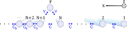
We study the formation of Fano surface localized modes in a planar optical waveguide array with one side-coupled waveguide as shown in Fig. 1. In analogy to the atomic physics context where Fano results were originally derived, this side-coupled waveguide is called the “autoionizing” waveguide (AW). The waveguide structure consists of a 1D chain of identical waveguides. The propagation direction and the transverse direction are and , respectively. The chain is coupled to the AW with strength . The part containing the waveguides to is a resonator region. Here, the coupling coefficient between neighboring waveguides is . We consider the general situation when the coupling strength in the “background” region, i.e., the semi-infinite array section containing the waveguides , , , is different. As we demonstrate below, the variation of the background coupling enables selective manipulation of Fano modes and regular exponentially localized modes.
We model the evolution of the optical mode amplitudes along the propagation direction using a coupled-mode approach with nearest-neighbor coupling Miroshnichenko et al. (2005),
| (1) |
where describes the optical mode amplitude in the -th waveguide. We put due to the array termination. In this formulation, the spectrum is centered around the propagation constant of an isolated waveguide.
We first consider the case of a homogeneous coupling in the waveguide array, . Then, the eigenvalues in the semi-infinite array for a continuous band in the region . By virtue of the dispersion relation , each supermode can be constructed from plane waves with wavenumber . The waveguide is a defect to the 1D chain and plane waves incident on the triangle of waveguides exhibit a transmission which is dependent on the value of . It is convenient to represent the field inside the resonator region () in terms of incident and reflected waves as and in the background region () the field will be the transmitted wave . One finds from Eq. (1) with that the transmission and reflection coefficients are
| (2) |
where . We note that the transmission vanishes at certain value of , which corresponds to a Fano resonance Miroshnichenko et al. (2005). At resonance, we have , i.e. defines the phase of the reflection coefficient. In order to use the Fano resonance to trap light in the resonator region, it is necessary to also satisfy the Fabry-Perot condition for one round-trip of the plane wave between the surface of the chain and the AW, which is formulated as
| (3) |
where is an integer. In this expression, the first term corresponds to phase accumulation for the waves propagation between the waveguides , the second term is the reflection phase from the Fano defect, and the third term is the reflection phase at the boundary . We find that the Fano and Fabry-Perot resonance conditions can be satisfied simultaneously when . In this case , and the Fabry-Perot resonances occur for , corresponding to the number of waveguides in the resonator region
In the following, the case is studied numerically and experimentally. For the experimental study, the waveguide array has to be finite, and we consider an array with all in all waveguides ( waveguides in the 1D chain plus the AW). We numerically calculate the spectrum of eigenmodes, and present it in Fig. 2(a). We find extended eigenstates with eigenvalues representing a quasi-continuum. Furthermore, as indicated by arrows in the figure we identify two localized states, which arise from the coupling of the AW with the 1D chain. The state indicated by a red arrow is a defect state residing inside the gap above the band of eigenvalues and it is thus exponentially localized (). The second state, indicated by the blue arrow, occurs at the eigenvalue corresponding to the Fano resonance, at it has a fundamentally different field structure with the zero amplitude in the background, i.e., this state strictly exists only between the edge and the AW. This property is referred to as “compactness”. Furthermore, the propagation constant of this Fano-compact state (FCS) resides inside the allowed propagation band. The Fano resonance does not break up the band of eigenvalues of the unperturbed 1D chain which makes the FCS a bound state in the quasi-continuum of the 1D chain.
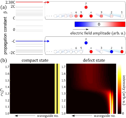
The vanishing of the electric field in waveguides does not allow any interaction of the FCS with the residual lattice. Therefore the state is completely insensitive to the lattice structure in the background. Hence, the FCS does not change if or the number of waveguides in the background is varied. Figure 2(b) demonstrates the change of the FCS (left) and the defect state (right) with increasing . By an increase of the propagation band broadens until the exponentially localized state is absorbed into the band, whereas the FCS remains unchanged at . The critical ratio of the coupling constants for which the exponentially localized state ceases to exist is .
A light beam coupled to the waveguide array will excite a superposition of different modes. The amplitudes of eigenstates will be proportional to the overlap of their spatial profiles with the input field distribution. For a single-waveguide excitation of the first site in the above structure, the amount of intensity dedicated to the FCS is . The defect state is only excited with a fraction of of the input intensity when , and this decreases further when .
For our experiments, we fabricated several waveguiding structures in fused silica using the femtosecond laser direct-writing approach Szameit and Nolte (2010). The samples are long, which is the maximum length feasible with our current fabrication technology. The experimental investigations now deal with two separate issues. First, observing the Fano resonance in an array with homogeneous coupling in the entire structure. Second, proving the compactness of the FCS by varying the coupling constant in the background. In order to directly observe the light evolution inside the structures we employ a fluorescence microscopy technique Szameit et al. (2007a). Among the possible single-waveguide excitations, the excitation of the first waveguide at the edge of the structure has the largest overlap with the FCS compared to the overlap with the defect state. In our experiments light at is launched into this waveguide using fiber butt coupling.
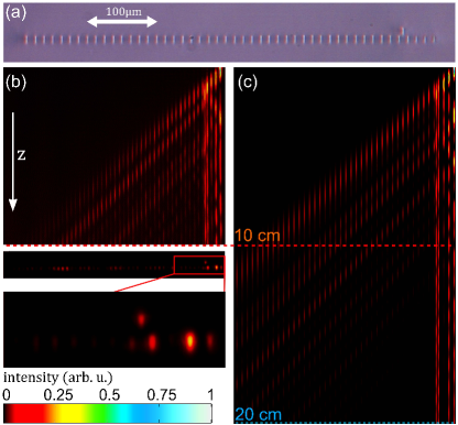
In a first set of experiments the spacing between neighboring waveguides of the chain is fixed to m, such that . This results in a coupling of about . Figure 3(a) shows the microscope image of the front facet of the fabricated array. Due to the strongly elliptical shape of the waveguides, resulting from the fabrication process, the coupling strength depends not only on the separation of the guides but also on their orientation with respect to the coupling direction Szameit et al. (2007b). The vertical offset () of the AW with respect to the chain was carefully tuned to match the condition . Equal coupling was achieved for .
The experimental data is shown in Fig. 3(b). When launching light into the edge waveguide of the structure, several eigenstates of the system are excited, including the FCS. Due to the reflection at the defect caused by the AW, the light carried by the extended eigenstates is transmitted gradually into the background. After cm propagation the intensity pattern in the resonator region is not perfectly reduced to the intensity pattern of the FCS. The transient behavior within the first five waveguides still includes intensity oscillations in each waveguide. However, the output pattern already exhibits the characteristic “dark” third waveguide [Fig. 3(b), lower part] identifying the FCS. The simulations, shown in Fig. 3(c), confirm the measured behavior. Even after 20cm propagation, the FCS is not established perfectly but the data in Fig. 3 is sufficient to confirm the existence of the FCS.
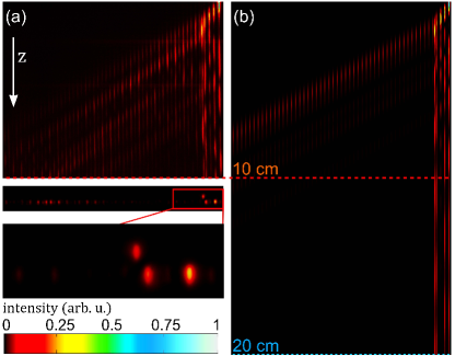
In the next experiment, we aim to demonstrate the “compactness” of the FCS. To this end, in a second sample we reduced the spacing in the background region to which corresponds to , whereas in the region close to the surface m spacing is reproduced. Therefore, the Fano resonance is expected at a similar height of the AW, compared to the first structure. Indeed, was here achieved for . The experimental data in Fig. 4(a) shows that an intensity distribution in the first five waveguides evolves to a final state which is very similar to that observed in the first experiment, c.f. Fig. 3(a). Our simulations of the light evolution in this structure [Fig. 4(b)] confirm this trend. This is the experimental confirmation that the FCS is independent of the topology of the background region of the 1D waveguide chain and, thus, the FCS is compact. Nevertheless, the transient behavior changes slightly. This is reasonable since the occupation of the eigenmodes has changed and except for the FCS, the profiles of eigenmodes are sensitive to the value of .
In this work, we have theoretically predicted and experimentally demonstrated the existence of a compact bound state in the continuum of one-dimensional waveguide array. This state is confined to a finite region of the array and exhibits no exponentially decaying tails. We found the condition when all localized states other then the compact state cease to exist.
Acknowledgments
This work was support by the Australian Research Council through Future Fellowship program (including FT100100160) and the
German Ministry of Education and Research (Center for Innovation Competence programme, grant 03Z1HN31). R. Keil was supported by the Abbe School of
Photonics.
Methods
Our samples are fabricated in bulk fused silica wafers using the femtosecond laser direct-write approach
(Szameit and Nolte, 2010) employing a Ti:Sapphire Mira/RegA laser system (Coherent Inc.) operating at a wavelength of 800 nm, a repetition rate
of 100 kHz and a pulse length of 170 fs. The light is focused inside the sample by a microscope objective (NA=0.35), and by continuously
moving the sample using a high-precision positioning system (Aerotech Inc.) the waveguides are created by the induced refractive index increase. For
the fabrication of our samples, the pulse energy was adjusted to 320 nJ and the writing velocity was set to 1.5 mm/s.
Author contributions
S. W. fabricated the samples and performed the experiments. S. W. and A. S. analyzed the data. Y. X., A. E. M., and A. A. S. developed the theory.
All authors co-wrote the manuscript.
Additional information
Correspondence and requests for materials should be addressed to A.S. (alexander.szameit@uni-jena.de)
Competing financial interests
The authors declare no competing financial interests.
References
- Boardman (1982) A. D. Boardman, ed., Electromagnetic Surface Modes (New York: Wiley, 1982).
- Maier (2007) S. A. Maier, Plasmonics: Fundamentals and Applications (Springer, 2007).
- D’yakonov (1988) M. I. D’yakonov, Sov. Phys. JETP 67, 714 (1988).
- Tamm (1932) I. E. Tamm, Phys. Z. Soviet Union 1, 733 (1932).
- von Neumann and Wigner (1929) J. von Neumann and E. Wigner, Z. Phys 30, 465 (1929).
- Stillinger and Herrick (1975) F. H. Stillinger and D. R. Herrick, Phys. Rev. A 11, 446 (1975).
- Friedrich and Wintgen (1985) H. Friedrich and D. Wintgen, Phys. Rev. A 32, 3231 (1985).
- Capasso et al. (1992) F. Capasso, C. Sirtori, J. Faist, D. L. Sivco, S.-N. G. Chu, and A. Y. Cho, Nature 358, 565 (1992).
- Longhi (2007) S. Longhi, The European Physical Journal B - Condensed Matter and Complex Systems 57, 45 (2007).
- Marinica et al. (2008) D. C. Marinica, A. G. Borisov, and S. V. Shabanov, Phys. Rev. Lett. 100, 183902 (2008).
- Bulgakov and Sadreev (2008) E. N. Bulgakov and A. F. Sadreev, Phys. Rev. B 78, 075105 (2008).
- Dreisow et al. (2008) F. Dreisow, A. Szameit, M. Heinrich, T. Pertsch, S. Nolte, A. Tünnermann, and S. Longhi, Phys. Rev. Lett. 101, 143602 (2008).
- Longhi (2009) S. Longhi, Journal of Modern Optics 56, 729 (2009).
- Bulgakov and Sadreev (2009) E. N. Bulgakov and A. F. Sadreev, Phys. Rev. B 80, 115308 (2009).
- Bulgakov and Sadreev (2010) E. N. Bulgakov and A. F. Sadreev, Phys. Rev. B 81, 115128 (2010).
- Otey et al. (2009) C. R. Otey, M. L. Povinelli, and S. H. Fan, Appl. Phys. Lett. 94, 231109 (2009).
- Plotnik et al. (2011) Y. Plotnik, O. Peleg, F. Dreisow, M. Heinrich, S. Nolte, A. Szameit, and M. Segev, Phys. Rev. Lett. 107, 183901 (2011).
- Molina et al. (2012) M. I. Molina, A. E. Miroshnichenko, and Y. S. Kivshar, Phys. Rev. Lett. 108, 070401 (2012).
- Fano (1961) U. Fano, Phys. Rev. 124, 1866 (1961).
- Miroshnichenko et al. (2010) A. E. Miroshnichenko, S. Flach, and Y. S. Kivshar, Rev. Mod. Phys. 82, 2257 (2010).
- Pan et al. (2008) J. Pan, Y. Huo, K. Yamanaka, S. Sandhu, L. Scaccabarozzi, R. Timp, M. L. Povinelli, S. Fan, M. M. Fejer, and J. S. Harris, Applied Physics Letters 92, 103114 (2008).
- Pan et al. (2010a) J. Pan, S. Sandhu, Y. Huo, N. Stuhrmann, M. L. Povinelli, J. S. Harris, M. M. Fejer, and S. Fan, Phys. Rev. B 81, 041101 (2010a).
- Pan et al. (2010b) J. Pan, Y. Huo, S. Sandhu, N. Stuhrmann, M. L. Povinelli, J. S. Harris, M. M. Fejer, and S. Fan, Applied Physics Letters 97, 101102 (2010b).
- Tanaka et al. (2007) Y. Tanaka, J. Upham, T. Nagashima, T. Sugiya, T. Asano, and S. Noda, Nat. Mater. 6, 862 (2007).
- Miroshnichenko et al. (2005) A. E. Miroshnichenko, S. F. Mingaleev, S. Flach, and Y. S. Kivshar, Phys. Rev. E 71, 036626 (2005).
- Szameit and Nolte (2010) A. Szameit and S. Nolte, J. Phys. B: At. Mol. Opt. Phys. 43, 163001 (2010).
- Szameit et al. (2007a) A. Szameit, F. Dreisow, H. Hartung, S. Nolte, A. Tuennermann, and F. Lederer, Applied Physics Letters 90, 241113 (2007a).
- Szameit et al. (2007b) A. Szameit, F. Dreisow, T. Pertsch, S. Nolte, and A. Tuennermann, Opt. Exp. 15, 1579 (2007b).