Propagation of the Gravo-Magneto Disc Instability
Abstract
Discs that contain dead zones are subject to the Gravo-Magneto (GM) instability that arises when the turbulence shifts from gravitational to magnetic. We have previously described this instability through a local analysis at some radius in the disc in terms of a limit cycle. A disc may be locally unstable over a radial interval. In this paper, we consider how the local instability model can describe global disc outbursts. The outburst is triggered near the middle of the range of locally unstable radii. The sudden increase in turbulence within high surface density material causes a snow plough of density that propagates both inwards and outwards. All radii inside of the trigger radius become unstable, as well as locally unstable radii outside the trigger radius. In addition, a locally stable region outside of the trigger radius may also become unstable as the gravitational instability is enhanced by the snow plough. For the circumstellar disc model we consider, we find that a quarter of the disc mass is accreted on to the central object during the outburst. The radius out to which the disc is globally unstable is twice that for which it is locally unstable.
keywords:
accretion, accretion disks –- planets and satellites: formation –- protoplanetary disks –- stars: pre-main sequence1 Introduction
Accretion discs are ubiquitous in the Universe, they form on all scales from planetary, to stellar, to galactic. They transport angular momentum outwards allowing material to spiral inwards through the disc (e.g. Pringle, 1981). If the disc is fully ionised, the magneto rotational instability (MRI) drives turbulence and thus angular momentum transport (Balbus & Hawley, 1991). However, below a critical level of ionisation, a dead zone may form at the mid-plane where the MRI does not operate (Gammie, 1996; Gammie & Menou, 1998; Turner & Sano, 2008). The inner parts of the disc are hot enough to be thermally ionised. However, further out, only the surface layers of the disc may be ionised by external sources such as cosmic rays or X-rays from the central star (Glassgold, Najita & Igea, 2004). The restricted flow through the disc causes a build up of material in the dead zone. If there is sufficient accretion infall, some turbulence in the dead zone may be driven by self-gravity when the layer becomes massive enough (Paczynski, 1978; Lodato & Rice, 2004). However, if it does not transport angular momentum fast enough, the gravo-magneto (GM) disc instability can result. This occurs when the temperature in the dead zone reaches the critical required for the MRI to be triggered and an accretion outburst ensues (Armitage, Livio & Pringle, 2001; Zhu, Hartmann & Gammie, 2009, 2010a; Zhu et al., 2010b; Martin & Lubow, 2011a).
The GM disc instability can be explained as transitions between steady state disc solutions plotted on a state diagram showing the accretion rate through the disc against the surface density for a fixed radius (Martin & Lubow, 2011a). There are three steady state disc solutions, two fully MRI turbulent solutions (one that is thermally ionised and one that is fully ionised by external sources such as cosmic rays or X-rays) and the GM solution. The GM solution consists of a self gravitating, MRI inactive mid-plane region with MRI active surface layers such that the flow through the disc is at the steady rate. For a given radius, there may be a range of accretion rates for which no steady solution exists. If the accretion rate on to the disc lies in this range then the disc will be locally GM unstable. The disc transitions between the steady thermal MRI and GM solutions cause repeating outbursts over time. This is similar to the “S-curve” used to explain dwarf nova outbursts (Bath & Pringle, 1982; Faulkner, Lin & Papaloizou, 1983).
For a range of radii in the disc, there exists a local limit cycle. In this work, we extend the model of Martin & Lubow (2011a) to consider how the local limit cycles at different radii are coordinated and thus how the global disc evolution operates. We examine the radius at which the outburst is triggered and how far the outburst propagates through the disc. We find that the radii are connected through a snow plough effect where the dense material is pushed both inwards and outwards during the outburst. Previous works have considered the propagation of the outburst (e.g. Armitage, Livio & Pringle, 2001; Zhu et al., 2010b), but not within the framework of the limit cycle.
The GM disc instability may occur in accretion discs on many scales. It is thought to describe FU Orionis outbursts in discs around young stellar objects (e.g. Armitage, Livio & Pringle, 2001; Zhu et al., 2010b; Martin et al., 2012a, b; Stramatellos et al., 2012). It is also likely to occur in circumplanetary discs that form around massive planets as they form within the circumstellar disc (Martin & Lubow, 2011b; Lubow & Martin, 2012a, b). In this work we restrict our analysis to that of a circumstellar disc, but note that the underlying mechanism is the same for all scales.
2 Local Disc Instability
The layered disc model we apply is based on Armitage, Livio & Pringle (2001) and further developed in Zhu et al. (2010b) and Martin & Lubow (2011a). Following Martin & Lubow (2011a), we first solve the steady state layered accretion disc equation
| (1) |
with the steady energy equation
| (2) |
where is the steady accretion rate through the disc, is the midplane temperature, is the surface density in the dead zone layer, is the MRI active surface density, the total surface density is , is the Keplerian angular velocity, is the optical depth of the magnetic layer and is the optical depth of the whole disc. The viscosity due to the MRI is
| (3) |
where is the sound speed in the active surface layers and is the Shakura & Sunyaev (1973) parameter in the layer. The disc is self-gravitating if the Toomre (1964) parameter is less than the critical, , and in this case depends on . The viscosity due to self-gravity is
| (4) |
where is the sound speed in the mid-plane layer and
| (5) |
for and zero otherwise (Lin & Pringle, 1987, 1990). We find that the exact form of does not affect the disc evolution provided it is a steeply declining function of (see also Zhu et al., 2010b, and the Discussion section).
In this work we consider a constant infall accretion rate, , on to the disc. For a steady disc solution, the infall accretion rate is equal to the accretion rate through the disc, , at all radii. However, if at some radius there is no steady solution, then the disc is unstable to the GM disc instability.
As described in the Introduction, there are three different steady solutions, two MRI active solutions and the GM solution. The fully MRI active solutions are found by setting . They exist in two regions of the disc, first in the inner parts where the mid-plane temperature is sufficiently high for thermal ionisation (, where is the temperature above which the MRI operates) and secondly in the outer parts where the surface density is sufficiently small that cosmic rays or X-rays penetrate the whole disc (, where is the critical surface density that is ionised through external sources). The third steady solution is the GM solution, where there is gravitational turbulence near the mid-plane and MRI turbulence in disc surface layers. This solution occurs where the mid-plane temperature is too low for the MRI () and the surface density is greater than the critical that can be ionised by external sources (), and large enough for the disc to be self-gravitating. The steady state solutions at a given radius cover a range of accretion rates. In general, there are cases where there is a gap in accretion rates for steady state solutions. Accretion rates that fall in that gap at some radius are locally unstable (Martin & Lubow, 2011a). For a fixed accretion rate on to the disc, there is generally a range of radii where that rate falls within the local gaps and thus a range of radii where the disc can be locally unstable.
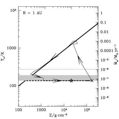
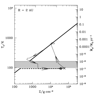
In this work we take an example of a circumstellar disc, but note that the same mechanisms apply to circumplanetary discs on a smaller scale. We choose a star of mass and a disc with a Shakura & Sunyaev (1973) viscosity parameter , and . Fig. 1 shows the state diagrams of the steady solutions at various radii in the disc. The surface temperature is shown against the surface density for the steady state solutions at a fixed radius. The surface temperature in the disc is related to an effective, steady accretion rate, , with
| (6) |
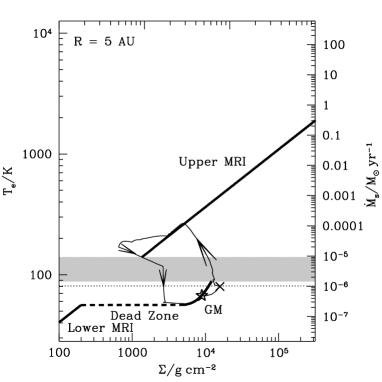
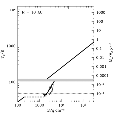
All radii shown, except , show the three steady branches. There are two fully MRI active solutions, the upper branch with and the lower branch with . The third branch is the self gravitating GM solution. The steady state solutions are shown in the solid thick lines and the dead zone branch (that is not a steady branch) is shown as the dashed line. The branches are labeled in the state diagram at . The shaded region is where there is no steady state solution and the disc is locally unstable. If the imposed disc accretion rate (infall accretion rate onto the disc), represented as the dotted line, lies within the shaded region, then the disc is locally unstable at that radius. The state diagram at a radius of does not have an unstable region because a fully MRI active disc solution exists at all accretion rates because either or .


2.1 Innermost Unstable Radius
For a disc with an unstable region, the innermost radius that is locally unstable occurs where the thermally ionised fully MRI active solution has a mid-plane temperature equal to the critical temperature. The surface density is larger than the critical that is ionised by external sources, if the unstable region exists.
This location can been seen in the state diagrams to occur at a radius where the accretion rate through the disc is such that it lies on the lower end of the upper MRI branch (similar to the middle left plot in Fig. 1). That is, the radius where the dotted line intersects the lower end of the upper, solid sloped line. The upper MRI branch begins where the mid-plane temperature is equal to the critical, . We scale the variables to , , and . We find steady state fully turbulent solutions (with and ). The radius at which the fully turbulent solution has the critical mid-plane temperature is
| (7) |
This is the innermost radius that is locally unstable to the GM instability.
2.2 Outermost Unstable Radius
The outermost radius for which no steady solution exists (and thus the disc is locally unstable to the GM instability) occurs where the GM solution has a mid-plane temperature equal to the critical. In the state diagram this is where the accretion rate through the disc lies at the upper end of the GM branch (similar to the lower left plot in Fig. 1). This is where the self gravitating, GM solution reaches the critical mid-plane temperature. We again solve the steady state equations, but now include the self gravitating term. However, the equations must be solved numerically. For an accretion rate of , we find the radius to be . Thus, the locally unstable region for this disc extends from to . Outside of this region there is a steady GM disc solution, and inside there is a fully MRI solution. We note that the innermost and outmost unstable radii in the disc do not necessarily correspond to the inner and outer edges of a dead zone in a time-dependent disc.
2.3 Outer Transition to MRI Branch
The outer parts of the disc are fully MRI active where the surface density is smaller than the critical, . This occurs at a radius
| (8) |
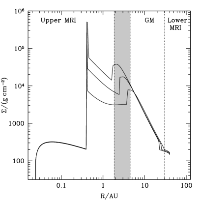
Hence, in summary, in the region the disc has a fully MRI active solution, the disc has no steady solution (and is locally unstable to the GM instability). In there is a steady GM solution. In the disc is fully MRI active. In Figs. 2 and 3 we label these regions as a function of radius in the disc and shade the region for which there is no steady solution.

3 Global Disc Instability


We solve the time-dependent accretion disc equations that consist of a surface density evolution equation (Pringle, 1981) and an energy equation (Pringle, 1986; Cannizzo, 1993). The equations are described in more detail in Martin & Lubow (2011a) (see their equations 1 and 3). We take a grid of 200 points equally spaced in that extends from to (e.g. Armitage, Livio & Pringle, 2001; Martin et al., 2007). At the inner boundary we have a zero torque boundary condition to allow the inward flow of gas on to the star. At the outer boundary, we choose a zero radial velocity condition to prevent material from leaving the disc there. There is a constant infall accretion rate on to the disc of at a radius of . As shown in the previous section, for this accretion rate the disc is locally unstable for a range of radii.
The disc evolves through several outbursts before the limit cycle repeats. Thus, the initial conditions of the disc have no effect on the limit cycles shown. Fig. 1 shows the local state diagrams, for various radii, of the surface temperature against the surface density. The thick lines show the analytic steady state solutions (as described in the previous section) and the thin lines show the numerical time-dependent evolution. The dashed line shows the steady infall accretion rate.
The crosses mark the position at the time when the outburst is triggered at that radius (i.e. where ), and the stars mark the position when the outburst is first triggered globally. For the case, the two positions coincide with the end of the GM branch and hence also with a temperature of . However, at other radii, the position when the outburst is triggered locally does not coincide with the position where it is triggered globally. Once the outburst is triggered somewhere in the disc, it propagates very quickly and adjacent radii undergo their limit cycles similarly fast. At , the mid-plane temperature of the disc does not drop below the critical during the cycle, hence there is no cross shown. Similarly, at , the mid-plane temperature during the cycle does not exceed the critical temperature and so there is no cross shown.
The outburst propagates inwards and hence all radii inside of the trigger radius show outburst behaviour. The total mass of the disc before the outburst is of which is within the dead zone and is not self-gravitating. During the outburst, a mass of is accreted on to the star. This amount of material is initially distributed up to a radius of (that roughly coincides with the trigger radius). The outburst also propagates outwards. The dead zone has a high surface density that suddenly becomes more turbulent when the MRI is triggered, causing material to move outwards. For example, at , the disc has a steady state GM solution. However, this solution is not found because of the outward propagation. The disc is depleted after an outburst, leaving a less massive and cooler disc than the steady state would predict. The disc moves towards the steady state but the outburst is first triggered at an accretion rate lower than the steady rate. Even further out, where the steady solution is lower down the GM branch, the outward propagation is not sufficient to trigger an outburst and the disc remains close to the GM branch and then moves downwards after the outburst. The outermost radius for which the disc moves up to the upper MRI branch during the outburst is around , twice the radius of outer edge of the locally GM unstable region.
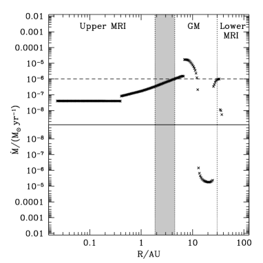
Fig. 2 shows the disc structure leading up to an outburst. The branch labels in the figure (Upper MRI etc.) refer to where steady state solutions exist. For the time-dependent evolution being plotted, these labels may not reflect the instantaneous structure at each radius. The shaded region shows where there is no steady state disc solution. The innermost parts of the disc are fully MRI turbulent. However, beyond radius of , the mid-plane temperature of the disc drops below the critical value. At this radius, , there is a sharp increase in the surface density and this marks the inner edge of the dead zone. The narrow density peak is due to a local pileup of gas. It is the result of the outward spread of turbulent gas from the active, inner (inside 0.41 AU) region into the nonturbulent dead zone where it cannot spread outward any further. The narrowness is a consequence of the sharp transition criteria we apply between active and dead zones. If we applied a smoother transition criteria, the peak would be spread out over a larger range of radii. The dead zone covers some of the region where there exists a steady state MRI disc solution (as labeled Upper MRI). This overlap exists because the outer parts of the flow near are limited to the accretion rate of the active surface layer. There is not sufficient flow in this region to reach the steady solution at the infall accretion rate.
The local peak in the surface density within the unstable region marks the radius in the disc at which the dead zone becomes self gravitating. This local peak moves inwards in time as material builds up. There is a similar local peak in the temperature profile that moves inwards slightly behind the surface density peak in time. Once this peak reaches the critical temperature required for the MRI, the outburst is triggered (as in the last time shown in Fig. 2). The outburst is first triggered at a radius of .
It is the outer parts of the dead zone that become self gravitating first (as shown in Fig. 2). Hence, in the limit cycles in Fig. 1, the larger the radius, the sooner the disc reaches the GM branch. However, the speed at which the disc moves up this branch, decreases with radius. As a function of radius, there is then opposite behavior in the time that the disc reaches this branch and the speed at which it travels up the branch. Hence, the outburst is triggered somewhere in the middle of the locally unstable region.
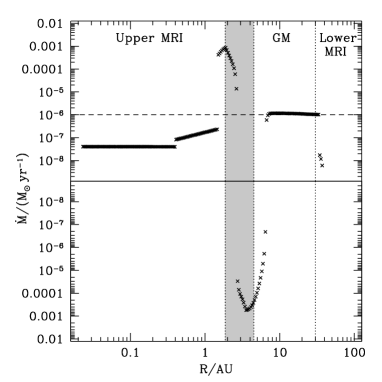
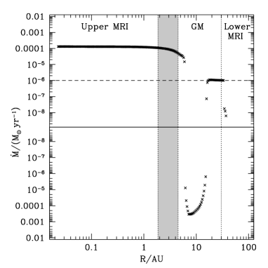
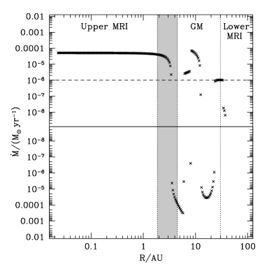
Fig. 3 shows the radius dependent accretion rate through the disc at various times during the outburst cycle. The upper portion of each plot represents the inward flow and the lower portion the outward flow. The top left plot shows the accretion rate just before an outburst, that corresponds to the upper lines for the surface density and temperature shown in Fig. 2. There are three main parts to the disc, the inner part that is fully MRI active, the middle part where there is a dead zone and the large outer part that is self gravitating. In the very outermost parts of the disc, the accretion drops off because there is a zero flow outer boundary condition. This only affects the parts of the disc outside of the radius where material is injected, at .
The top right hand plot shows the accretion rate shortly after the outburst is triggered. There are both inward and outward propagating waves moving away from the trigger point at . This is the snow plough effect, material moves both inwards and outwards away from the trigger radius. It is this snow plough that causes the various radii to be coordinated. The middle left plot shows the inner wave has propagated all the way in and the disc is now in outburst phase with a high accretion rate on to the star. The outward propagating waves continue to move outwards. In the middle right hand plot, the dead zone has begun to re-form. This initially occurs at a radius of . The dead zone formation propagates both inwards and outwards as seen in the lower left plot. As the dead zone forms, the viscous torque there drops. Thus, material just interior to the dead zone initially moves outwards because the outward viscous torque is larger than the inward torque. This is the cause of the narrow peak in the surface density at the inner edge of the dead zone (as described in Fig. 2). Eventually the inner parts of the disc move back to the quiescent phase as the dead zone blocks the flow, as seen in the bottom right hand plot. This marks the end of the outburst, although there is still some ongoing outward propagation in the outer regions. The material in the disc builds up again as shown in Fig. 2 until the cycle repeats.
4 Discussion
There are a number of simplifications in our model that should be investigated in future work. Some of these were discussed in more detail in Martin & Lubow (2011a) and Lubow & Martin (2012a). For example, we have assumed that the critical surface density that is ionised by external sources in constant with radius. However, a more realistic way to find the extent of the dead zone may be with a critical magnetic Reynolds number (e.g. Fleming, Stone & Hawley, 2000; Matsumura & Pudritz, 2003). The critical value however remains uncertain (e.g. Martin et al., 2012b). The ionisation may be further suppressed by effects such as ambipolar diffusion and the presence of dust and polycyclic aromatic hydrocarbons (e.g. Bai & Goodman, 2009; Bai, 2011; Perez-Becker & Chiang, 2011; Simon et al., 2012; Dzyurkevich et al., 2013). No matter how the dead zone is determined, the outburst mechanism works in the same way. The shape of the limit cycle may be slightly different (see Martin et al., 2012a), but the principles remain the same.
There remains some uncertainty in the prescriptions for the viscosities in the disc. Observations of the fully MRI turbulent discs in dwarf novae and X-ray binaries suggest (King, Pringle & Livio, 2007). However, in discs around T Tauri stars, such a high would cause the outer discs to expand too quickly (Hartmann et al., 1998). Moreover, theoretical work suggests a smaller (e.g. Fromang et al., 2007). We have taken in this work, but note that the qualitative evolution of the disc would be similar had we taken a larger value for . There is also some uncertainty in the value of in a self gravitating disc. But its exact value has little influence of the disc structure and evolution, as noted by Zhu, Hartmann & Gammie (2010a). Within the self gravitating region the Toomre parameter in our model is nearly constant, . In our prescription the value of is not fixed and depends on the Toomre parameter, . In steady state, implicitly it varies with the local cooling timescale, , such that (see also Gammie, 2001).
In a real disc the infall accretion rate is not likely to be constant in time, but rather decrease. The locally unstable region would decrease in time until the accretion rate is so low that a fully MRI active solution is found. For the parameters chosen in this work, this would be for accretion rates .
The existence of dead zones in protoplanetary discs may have important implications for planet formation. Planets that survive after the disc has dispersed (e.g. by photoevaportation Hollenbach et al., 1994; Alexander, Clarke & Pringle, 2006) likely formed after the final GM disc outburst. If planets form between outbursts, they likely accrete on to the star during the outburst. As the infall accretion rate drops over time, the outbursts cease but a dead zone may remain. This dead zone provides a quiescent region suitable for planet formation. The presence of a dead zone also affects the migration of planets through the disc. Planets embedded in low viscosity discs can undergo very slow and sometimes chaotic migration (Li et al., 2009; Yu et al., 2010). The nature of gap opening and migration of planets through a layered disc should be investigated in future work.
5 Conclusions
The GM disc instability can be explained as transitions between steady state solutions in a state diagram that plots the surface temperature against the surface density at a fixed radius. We have examined local cycles at different radii. There is a range of radii for which a given disc is locally GM unstable. For the parameters chosen in this work (, , and ), we find the unstable range to be .
The outburst is first triggered in the middle of the range of locally unstable radii. For the parameters we chose, the trigger radius is at . The resulting snow plough of material that propagates both inwards and outwards links the different radii in the disc. All radii inside of the trigger radius become unstable and the mass in this region moves inwards to be accreted during the outburst. The snow plough effect pushes material outwards through the disc to radii which would otherwise lie along the steady GM branch and be locally stable. The higher density causes these outer radii to also become unstable. The outburst propagates to a radius of around , about double that of the outermost locally unstable radius. Even further out than this, there are increases in density but these are not sufficient for a change in the state.
Acknowledgements
We thank the anonymous referee for useful comments. RGM’s support was provided in part under contract with the California Institute of Technology (Caltech) funded by NASA through the Sagan Fellowship Program. SHL acknowledges support from NASA grant NNX11AK61G.
References
- Alexander, Clarke & Pringle (2006) Alexander R. D., Clarke C. J., Pringle J. E., 2006, MNRAS, 369, 229
- Armitage, Livio & Pringle (2001) Armitage P. J., Livio M., Pringle J. E., 2001, MNRAS, 324, 705
- Bai & Goodman (2009) Bai, X. -N., Goodman J. 2009, ApJ, 701, 737
- Bai (2011) Bai X. -N., 2011, ApJ, 739, 50
- Balbus & Hawley (1991) Balbus S. A., Hawley J. F., 1991, ApJ, 376, 214
- Bath & Pringle (1982) Bath G. T., Pringle J. E., 1982, MNRAS, 199, 267
- Cannizzo (1993) Cannizzo J. K., 1993, ApJ, 419, 318
- Dzyurkevich et al. (2013) Dzyurkevich N., Turner N. J., Henning T., Kley W., 2013, ApJ, 765, 114
- Faulkner, Lin & Papaloizou (1983) Faulkner J., Lin D. N. C., Papaloizou J., 1983, MNRAS, 205, 359
- Fleming, Stone & Hawley (2000) Fleming T. P., Stone J. M., Hawley J. F., 2000, ApJ, 530, 464
- Fromang et al. (2007) Fromang S., Papaloizou J., Lesur G., Heinemann T., 2007, A&A, 476, 1123
- Gammie (1996) Gammie C. F., 1996, ApJ, 457, 355
- Gammie & Menou (1998) Gammie C. F., Menou K., 1998, ApJ, 492, 75
- Gammie (2001) Gammie C. F., ApJ, 553, 174
- Glassgold, Najita & Igea (2004) Glassgold A. E., Najita J., Igea J., 2004, ApJ, 615, 972
- Hartmann et al. (1998) Hartmann L., Calvet N., Gullbring E., D’Alessio P., 1998, ApJ, 495, 385
- Hollenbach et al. (1994) Hollenbach D., Johnstone D., Lizano S., Shu F., 1994, ApJ, 428, 654
- King, Pringle & Livio (2007) King A. R., Pringle J. E., Livio M., 2007, MNRAS, 376, 1740
- Li et al. (2009) Li H., Lubow S. H., Li S., Lin D. N. C., 2009, ApJ, 690, L52
- Lin & Pringle (1987) Lin D. N. C., Pringle J. E., 1987, MNRAS, 225, 607
- Lin & Pringle (1990) Lin D. N. C., Pringle J. E., 1990, ApJ, 358, 515
- Lodato & Rice (2004) Lodato G., Rice W. K. M., 2004, MNRAS, 351, 630
- Lubow & Martin (2012a) Lubow S. H., Martin R. G., 2012a, ApJ, 749, 37
- Lubow & Martin (2012b) Lubow S. H., Martin R. G., 2012b, MNRAS, 428, 2668
- Martin et al. (2007) Martin R. G., Lubow S. H., Pringle J. E., Wyatt, M. C., 2007, MNRAS, 378, 1589
- Martin & Lubow (2011a) Martin R. G., Lubow S. H., 2011a, ApJ, 740, L6
- Martin & Lubow (2011b) Martin R. G., Lubow S. H., 2011b, MNRAS, 413, 1447
- Martin et al. (2012a) Martin R. G., Lubow S. H., Livio M., Pringle J. E., 2012a, MNRAS, 423, 2718
- Martin et al. (2012b) Martin R. G., Lubow S. H., Livio M., Pringle J. E., 2012b, MNRAS, 420, 3139
- Matsumura & Pudritz (2003) Matsumura, S., Pudritz, R. E. 2003, ApJ, 598, 645
- Paczynski (1978) Paczynski B., 1978, AcA, 28, 91
- Perez-Becker & Chiang (2011) Perez-Becker D., Chiang E., 2011, ApJ, 727, 2
- Pringle (1981) Pringle J. E., 1981, ARA&A, 19, 137
- Pringle (1986) Pringle J. E., Verbunt F., Wade R. A., 1986, MNRAS, 221, 169
- Shakura & Sunyaev (1973) Shakura N. I., Sunyaev R. A., 1973, A&A, 24, 337
- Simon et al. (2012) Simon J. B., Bai X., Stone J. M., Armitage P. J., Beckwith K., 2013, ApJ, 764, 66
- Stramatellos et al. (2012) Stamatellos D., Whitworth A. P., Hubber D. A., 2012, MNRAS, 427, 1182
- Toomre (1964) Toomre A., 1964, ApJ, 139, 1217
- Turner & Sano (2008) Turner N. J., Sano T., 2008, ApJ, 679, 131
- Yu et al. (2010) Yu C., Li H., Li S., Lubow S. H., Lin D. N. C., 2010, ApJ, 712, 198
- Zhu, Hartmann & Gammie (2009) Zhu Z., Hartmann L., Gammie C., 2009, ApJ, 694, 1045
- Zhu, Hartmann & Gammie (2010a) Zhu Z., Hartmann L., Gammie C., 2010a, ApJ, 713, 1143
- Zhu et al. (2010b) Zhu Z., Hartmann L., Gammie C. F., Book L. G., Simon J. B., Engelhard E., 2010b, ApJ, 713, 1134