Luminosity measurement at ILC
Abstract
In this paper we describe a method of luminosity measurement at the future linear collider ILC that estimates and corrects for the impact of the dominant sources of systematic uncertainty originating from the beam-induced effects and the background from physics processes. Based on the relativistic kinematics of the collision frame of the Bhabha process, the beam-beam related uncertainty is reduced to a permille independently of the precision with which the beam parameters are known. With the specific event selection, different from the isolation cuts based on topology of the signal used at LEP, combined with the corrective methods we introduce, the overall systematic uncertainty in the peak region above 80% of the nominal center-of-mass energy meets the physics requirements to be at the few permille level at all ILC energies.
keywords:
Accelerator modeling and simulations (multi-particle dynamics; single-particle dynamics), Detector modeling and simulations II (electric fields, charge transport, multiplication and induction, pulse formation, electron emission, etc.), Calorimeter methods1 Introduction
Integrated luminosity measurement at a future linear collider will be performed by counting Bhabha events reconstructed in the luminometer fiducial volume (FV) within specified event selection. To match the physics benchmarks (i.e. W-pair production, fermion pair-production, cross-section measurements) that might be of particular interest for the new physics, luminosity should be known at the level of or better [1]. In this paper we present the method of measurement optimized to meet the requirements for luminosity precision. Using MC simulation of the relevant physics and beam-induced processes, we show that the luminosity can be measured in the peak region above 80% of the nominal center-of-mass (CM) energy with a relative precision of a few permille at all ILC energies. In addition, luminosity spectrum can be precisely reconstructed in the same energy region from the experimentally measurable quantities.
Finely granulated calorimeters, of high energy and polar angle resolution, are foreseen to instrument the very forward region at ILC. Luminometer at a future linear collider will be designed as a compact sampling calorimeter with Moliere radius of approximately 1.5 cm [2]. To reduce systematic biases from the mechanical precision of the alignment, a laser based monitoring system has been developed for ILC to control the position of the luminometer over short distances within a micron [3]. ILD detector model [1] for ILC is assumed at CM energies of 500 GeV and 1 TeV. Design of the luminometer is described in Section 2. Event simulation used to establish the presented method of luminosity measurement is described in Section 3.
With the rising energy and the bunch density, one of the main uncertainties in luminosity measurement at a future collider at TeV energies comes from the effects induced by space charges of the opposite beams. Beamstrahlung and electromagnetic deflection induced by the field of the opposite bunch, together with the initial state radiation (ISR), result in the change of the four-vectors of the initial and final state particles, consequently causing the deviation of the polar angles and counting losses of the signal in the luminometer. Dominating beamstrahlung effects are particularly pronounced at higher CM energies, resulting in 12.8% counting loss at 500 GeV at ILC [4], assuming beam parameters from Ref. [5] and 18% counting loss in the 3 TeV CLIC case [6], in the upper 20% of the luminosity spectrum. If the full energy range is considered, counting losses are more severe ranging up to the 70% at 3 TeV CLIC. Corrective methods developed to take this into account are reviewed in this paper for the 500 GeV and 1 TeV ILC cases in Sections 4.1.1 and 4.1.2.
Due to the precision requirements of luminosity measurement, background from physics processes is discussed as another important source of systematic uncertainty. Electron spectators from the four-fermion processes can be misidentified as signal since they are emitted at low angles and with high energy. These processes can be, in principle, efficiently suppressed by the LEP type isolation cuts based on the signal topology [7, 8] that can not be directly translated to the linear collider case where beam-induced effects have to be simultaneously taken into account. Physics background in luminosity measurement is discussed in detail in Section 4.2.
Summary on systematic uncertainties in luminosity measurement is given in Section 4.3.
2 Luminometer at ILC
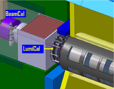
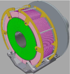
Two concepts of particle detectors are being developed for ILC, the International Large Detector (ILD) [1] featuring a Time Projection Chamber as the central tracking system and the Silicon Detector (SiD) [9] with a compact semiconductor central tracker designed to optimize the physics performance, as well as the cost. Both detectors have similar layout, combining excellent tracking and finely-grained calorimetry, which enables energy reconstruction of individual particles using particle flow algorithm [10]. To provide jet separation in multi-jet processes, electron identification down to the lowest polar angles, as well as a good hermeticity, the very forward region is instrumented with the two special calorimeters: luminometer designed to measure the rate of the low angle Bhabha scattering and the beam calorimeter that will allow fast luminosity estimate and measurement of the beam parameters. Layout of the very forward region of the ILD detector is illustrated in Figure 1 (left) [1]. Both the ILD and SiD concepts share the same design of the luminometer, the only difference being in the relative longitudinal positioning of the luminometer with respect to the IP. The present study refers to the ILD geometry.
The luminometer itself is foreseen as a sampling silicon/tungsten calorimeter, consisting of 30 absorber planes, each with thickness of one radiation length (3.5 mm), interspersed by segmented silicon sensor planes. To keep the Moliere radius of 1.5 cm, sensor gaps are kept at 1 mm. As illustrated in Figure 1 (right), tungsten disks are precisely positioned using 4 bolts. The system is additionally stabilized by steel rings. The accuracy of the electron polar angle reconstruction depends on the sensor segmentation. The optimized layout contains 48 azimuthal and 64 radial divisions, yielding a predicted angular resolution of mrad and the polar angle bias mrad [2]. Polar angle measurement bias, due to the clustering algorithm [11], is defined as the central value of the difference between the reconstructed and the true value of the polar angle. Non-zero values of the polar angle bias are induced by the non-linear signal sharing of finite size pads with gaps between them. The contribution of each of these two uncertainties to the relative uncertainty of luminosity measurement is [2]. In the ILD version, the luminometer is positioned at 2.5 m from the IP, with the geometrical aperture between 31 mrad and 78 mrad. Inner and outer radius are 80 mm and 195.2 mm respectively. Since the cross-section for Bhabha scattering is falling with the polar angle as , the inner aperture of the luminometer has to be known below the permille [12] to keep the counting uncertainty below permille. The constraint on relative lateral position of the IP with respect to the LumiCal is much less strict because of the averaging over the azimuthal angle. An uncertainty of several hundred microns in the relative lateral IP position induces an uncertainty of on the luminosity measurement [12].
With 30 radiation lengths of tungsten as the absorber, high energy electrons and photons deposit almost all of their energy in the detector. The relative energy resolution is parametrized as:
| (1) |
where and are, respectively, the central value and the standard deviation of the distribution of the energy deposited in the sensors for a beam of electrons with energy . The sampling parameter is usually quoted as the energy resolution and it is estimated to be [2] for electron showers located inside the FV of the luminometer. The detector FV, where is practically constant over , extends from 41 to 67 mrad.
3 Event simulation
3.1 Simulation of the signal influenced by the beam-induced effects
To simulate the influence of the beam-induced effects on signal, Guinea-Pig software 1.4.4 [13] was used to simulate the collisions of bunches. At the point when the initial four-momenta of the colliding pairs are generated, the decision is made by Guinea-Pig whether the Bhabha scattering will be realized in the collision. The decision is made randomly, based on the cross-section for the Bhabha scattering at the CM energy of the colliding pair. If Bhabha event is to be realized, the final four-momenta are picked from a file generated at the nominal ILC CM energy (500 GeV, 1 TeV) with the BHLUMI V4.04 generator [14]. The BHLUMI generator was run with the cuts on the polar angles in the laboratory frame and . After generation, post-generator cuts were applied on the scattering angle in the collision frame, and only events with were kept in the event file to be read by the Guinea-Pig. The cuts on the scattering angle are somewhat wider than the angular range of the luminometer FV to ensure a safety margin for the angular shift due to EMD and off-axis radiation. On the other hand, the cuts in the lab frame are relaxed because the longitudinal boost due to beamstrahlung requires a much wider margin. The momenta from the generator file are then scaled to the CM energy of the colliding pair, rotated to match the collision axis and then boosted back to the laboratory frame. Finally, electromagnetic deflection of the final state is simulated using the Guinea-Pig feature to predict the final deflection angles.
The standard beam-parameter set from the ILC Technical Progress Report 2011 [5] was used as the basis for both 500 GeV and 1 TeV simulations. Variations of individual beam parameters are taken into account in order to determine the influence of the beam-parameter uncertainties on the performance of the presented method (Section 4.1.1). Simulated beam-parameter variations include:
-
•
Symmetric bunch size variations by and and one-sided variations by +20% in , , ;
-
•
Symmetric bunch charge variations by and and one-sided +20% variation;
-
•
Relative misalignment of the two beams in the x- and y-directions by up to one respective bunch RMS width.
Thus, 25 sets of beam parameters were simulated in total for each of the two ILC energy options. In each simulation, one single beam parameter was varied with respect to its nominal value. Between 1.5 and 4 million Bhabha events were generated in each simulation. The interaction with the detector was approximated in the following way:
-
•
The four-momenta of all electrons and photons, that are treated as indistinguishable, are summed together in the 5 mrad cone around the most energetic shower. The 5 mrad criterion corresponds closely to the Molière radius of the high-energy showers in the LumiCal [11]. The initial beamstrahlung photons were not included as they are emitted close to the beam axis. For synchrotron radiation, the characteristic emission angles are of the order , being smaller than mrad for electron energies in the TeV range, therefore the four-momenta of photons emitted by the outgoing electrons can be added.
-
•
The energy resolution of the luminometer is simulated by adding random fluctuations to the final particle energies. The random fluctuations were sampled from the Gaussian distribution with the energy-dependent standard deviation.
-
•
The finite angular resolution of the luminometer is included by adding random fluctuations to the final particle polar angles corresponding to the luminometer resolution in polar angle as given in Section 2.
3.2 Simulation of physics background
Four-fermion events are generated at tree level at 500 GeV and 1 TeV CM energy, with the total corresponding cross-section of nb and nb respectively, using WHIZARD-V1.2 event generator [15]. Parameters of the event generation are tuned using to describe the experimental results obtained by several experiments at lower energy at PETRA and LEP accelerators [16]. Thus the physics background is generated under the following assumptions:
-
•
Mandelstam invariant mass of the outgoing lepton pair is greater than 1 GeV2,
-
•
Momentum transfered by the photon exchange is greater then GeV,
-
•
Events were generated within the polar angle range between 0.05 and 179.95 degrees to avoid the divergence of the cross-section at low polar angles.
Matrix elements for the leading order Feynman diagrams are computed using O’Mega generator [17]. The total sizes of samples correspond approximately to 1 million of background events integrated over the polar angle range at each ILC energy. The cross section for background processes integrated in the polar angle range of the luminometer FV is approximately a percent of the generated one.
Influence of physics background is estimated against the signal samples of 20 pb-1 of Bhabha events, with the cross-sections in the luminometer fiducial volume of = (4.689 0.001) nb and = (1.1970.005) nb at 500 GeV and 1 TeV CM energy, respectively. Estimated errors of the cross-sections are statistical. Signal is simulated with the BHLUMI event generator [14] implemented in BARBIE V5.0 [18], a GEANT4 [19] based detector simulation of the luminometer at ILC.
4 Luminosity measurement
4.1 Method of luminosity measurement
Luminosity at electron-positron collider is measured using Bhabha scattering at low angles () as a gauge process, which is calculable with excellent precision in QED. This is dominantly electromagnetic process (99% at ILC energies [20]) of one-photon exchange in the t-channel for which the cross-section calculations with relative uncertainty better than are available [21]. Luminosity at ILC will be measured by counting Bhabha scattering events that are recognized by coincident detection of showers in the two halves of luminometer. Unless distorted by the beam-induced effects, these showers are collinear and carry the largest fraction of the available CM energy. The luminosity integrated over certain period of time is calculable as the number of Bhabha events, , divided by the theoretical cross-section for the Bhabha scattering, .
| (2) |
In the most general view, equation (4.1) translates to:
| (3) |
Here , stands for angular parameters and energy of the final state particles; the superscript specifies whether these quantities are evaluated in the laboratory or the CM frame; and (resp. ) represent the ensemble of selection criteria and kinematic cuts applied to the event selection (resp. the cross-section evaluation). The notation emphasizes that and operate on kinematical arguments in different reference frames. The cross section is typically calculated by the Monte Carlo integration using an event generator in the CM frame of the process, under assumptions expressed by . On the other hand, Bhabha particles are experimentally reconstructed in the laboratory frame under certain selection criteria . In addition, the final state four-momenta are affected by the beam-beam effects. Because of random and asymmetric emission of the beamstrahlung and ISR, the CM frame of the Bhabha process is different for every colliding pair and in general it does not coincide with the laboratory frame. The resulting axial boost of the outgoing particle angles induces angular acceptance loss of the signal in the detector FV. An additional systematic bias of the order of 1 to 2 permille [4, 22] is induced by the electromagnetic deflection (EMD) of the outgoing Bhabha particles in the field of the opposite bunches.
At LEP, angular counting losses were usually addressed by applying selection in polar angles of the final state particles that is asymmetric with respect to the forward and backward side of the luminometer [23, 24, 25]. In order to minimize the beam induced effects on Bhabha counting rate, similar techniques were proposed for ILC as well [12, 22] where the beam-beam effects are much more intense. The beam-induced bias minimized in this way is then corrected by application of beam-beam simulation to determine the correlation between the bias and the form of the reconstructed luminosity spectrum. The above mentioned corrective techniques are simulation dependent and the systematic uncertainty of luminosity measurement depends on the knowledge of the beam parameters (i.e bunch sizes) [22].
To overcome these limitations, a concept introduced in Ref. [6] is used, in which one defines and in such a way that the counting rate is independent of reference frames in which these functions act. In the following section we briefly review this method and test it in the ILC case using MC simulation. The EMD effect requires a different approach that will be discussed in Section 4.1.2. In addition, event selection has to be established in a way to suppress the background from physics processes present in the very forward region (Section 4.2).
4.1.1 Collision-frame method
The collision frame of a scattering reaction is defined here as the CM frame of the electron-positron system after emission of ISR and before the emission of FSR. In the collision frame the deflection angles of both colliding particles are the same due to the momentum conservation principle. The movement of the collision frame with respect to the laboratory frame is responsible for the acollinearity leading to the angular counting loss. Since the kinematics of the detected showers correspond to the system after ISR, the velocity of the collision frame can be calculated from the measured polar angles. Since Beamstrahlung and ISR are approximately collinear with the incoming electrons, can be taken to be approximately collinear with the -axis. Under this approximation, the modulus of can be expressed as:
| (4) |
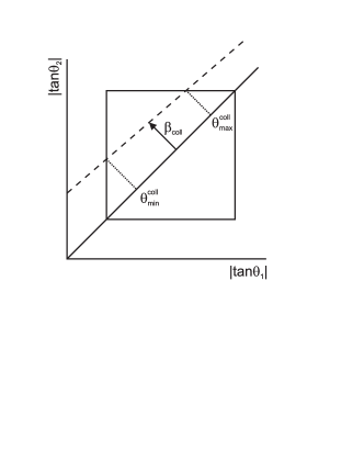
Due to the longitudinal boost of the final particle angles, the effective acceptance of Bhabha events in the luminometer decreases with increasing (see Figure 2). The effective limiting scattering angles and in the collision frame for a given are obtained by boosting and into the collision frame. This allows calculating the event-by-event weighting factor to compensate for the loss of acceptance:
| (5) |
For larger than some critical value (approximately 0.24 in the ILC case [26]), the effective angular acceptance is zero and such events are irreducibly lost. In all other cases, the counting loss can be corrected using Equation 5.
This correction method was tested using the simulation described in Section 3.1. The performance of the method is tested by comparison of the corrected CM energy spectrum of Bhabha-events to the control spectrum obtained by event selection based on the scattering angle in the collision frame, so the control spectrum corresponds to the signal events as if they were unaffected by the counting loss due to the longitudinal boost caused by Beamstrahlung and ISR. The results are shown in Figure 3 for the 1 TeV case. The control spectrum is plotted in black, the spectrum affected by the counting loss in red, the corrected spectrum in green. The blue line represents the events for which .
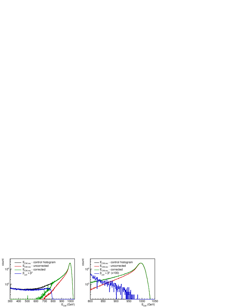
As can be seen from Figure 3, despite severe counting losses due to beamstrahlung and ISR, the agreement after correction is excellent above 80% of the nominal CM energy (800 GeV). The range below 80% of the nominal CM energy is dominated by events for which . Due to kinematic constraints, high values of are possible only with high energy loss, which explains the sudden drop of such events at 80% of the nominal CM energy. However, a small number of events with apparent is present also at energies above 80% of the nominal CM energy, because occasionally the assumption that is collinear with the beam axis is broken due to off-axis ISR.
The following is the list of sources of systematic uncertainty of the presented correction method:
-
1.
Off-axis ISR. In rare events with significant off-axis ISR, the assumption that is collinear with the beam axis does not hold,
-
2.
The implicit assumption that the cluster around the most energetic shower always contains the Bhabha electron. In a small fraction of events of order of a few permille, this is not the case and the reconstructed polar angles may differ from the final electron angles.
-
3.
The use of the approximate angular differential cross section for the Bhabha scattering in the calculation of ,
-
4.
Assumption in the calculation of and that all ISR is lost and all FSR is detected.
The relative bias due to the off-axis ISR is in the 500 GeV case and in the 1 TeV case. This bias is related to the energy and angular distributions of the ISR, which is reliably predicted by the generator. Thus this bias can be reliably corrected, and it is not sensitive to beam-parameter variations. In all simulations with the beam-parameter variations described in Section 3.1, the bias due to off-axis ISR is constant to within 0.1 permille.
The uncertainty introduced by the implicit assumption that the cluster around the most energetic shower always contains the Bhabha electron depends on the beam parameters and it may even depend on the specifics of the position-reconstruction algorithm in the luminometer. Therefore its correction will not be attempted here. The contribution of the effects 3 and 4 is smaller than the statistical uncertainty of the present analysis. The final quoted uncertainty will thus contain the contributions from the effects 2, 3 and 4.
In the following we present the numerical results of the correction method in terms of the fractional difference of the integral of the corrected to the control spectrum above 80% of the nominal CM energy. In all individual simulations with beam-parameter variations described in Section 3.1, the fractional difference is compatible with zero within the statistical uncertainty of the simulation, which is below permille in all individual simulations. For the overall precision, we quote the average over the entire set of simulations, for both energy options separately. Before correction of the bias due to off-axis ISR, the average fractional difference, containing contributions from all four systematic effects quoted above is in the 500 GeV case and in the 1 TeV case. After correction for the off-axis ISR, the remaining average fractional difference due to systematic effects number 2, 3 and 4 is at 500 GeV and at 1 TeV. The absolute size of these final biases can be taken as the present estimate of the uncertainty of the luminosity measurement induced by beamstrahlung and ISR.
One should note that the collision-frame method provides an accurate, simulation-independent correction of the angular counting loss of Bhabha events in the upper 20% of energy spectrum. It does not correct for the beamstrahlung induced counting losses below 80% of the nominal CM energy. The angular counting loss is reduced from ca. 10% to ca. one permille in a simulation-independent way. Part of the remaining bias, due to off-axis ISR, is corrected by using the MC simulation result.
4.1.2 Electromagnetic deflection
Electromagnetic field of the opposite bunch is causing shift of the outgoing particles toward smaller polar angles. This shift is rather small, but since the Bhabha cross section is monotonously decreasing with the polar angle, the net effect of EMD is a decrease of the Bhabha count. This effect is equivalent to the effect of a parallel shift in the angular limits and of the FV in the opposite direction by an effective mean deflection angle .
| (6) |
The proportionality coefficient between and the fractional counting loss is a quantity directly accessible in the analysis of either experimental or simulated data. On the other hand, to estimate beam-beam simulation has to be employed.
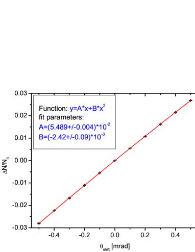
Figure 4 shows the fit of for the standard set of beam parameters at 1 TeV. is the fractional difference in counts in the shifted counting volume versus the FV . The parameter is obtained as the slope of at the zero shift angle. The result in the simulation for the standard beam parameters is . In the same simulation, the value of the fractional counting bias was , which gives the resulting effective mean deflection angle . In the same manner, obtained at 500 GeV CM energy is .
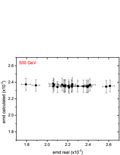
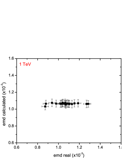
The value of obtained in this way can be used in the experiment to determine . The limitation of this correction is that it depends on simulation and on the precision of the knowledge of the beam parameters. Figure 5 shows the scatter plot of the values of obtained in this way versus the values of obtained directly from the difference in counts, for the set of beam-parameter variations described in Sec. 3.1. The absolute value of the fractional counting error due to such beam-parameter variations is always smaller than in the 500 GeV case and in the 1 TeV case. If the beam parameters are known with better precision (as discussed in [27]), the residual uncertainty of the EMD effect on integrated luminosity will be correspondingly smaller.
4.2 Background from physics processes
4.2.1 Two-photon processes
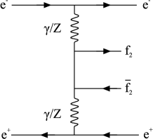
Another major systematic effect in the luminosity measurement originates from the four-fermion neutral-current processes of the type . These processes have Bhabha like signature characterized by the outgoing pairs emitted very close to the beam pipe, carrying a large fraction of energy so they can be miscounted as a signal. The leading order Feynman diagram is given in Figure 6. The dominant contribution to the cross section comes from the multiperipheral (two-photon exchange) process.
Due to the steep polar angle distribution of the produced particles, only a few permille of the produced primary pairs are deposited in the luminometer. The rest is detected in the beam calorimeter. Thus physics background is present in only 6.0 (2.2) permille at 500 GeV (1 TeV) of signal cases before any selection applied. Energy and polar angle distributions of signal and physics background in the acceptance region of the luminosity calorimeter, at 500 GeV CM energy are given in Figure 7. Similar distributions are obtained at 1 TeV CM energy. In Figure 7 (left), depositions at the nominal beam energy come from the electron spectators. Physics background polar angle distribution is similar to the one for the signal (Figure 7, right), confirming the very forward nature of the four-fermion production.


4.2.2 Event selection
In this paper we propose a selection that minimizes the overall impact of the leading systematic effects (beam-induced effects, background from physics processes) on the uncertainty of the integral luminosity measurement. Performance of the proposed selection is described by the two variables, signal efficiency and background rejection :
| (7) |
where , correspond to the number of coincidently detected pairs at the opposite sides of luminometer, for signal and background respectively, while the prime values correspond to the number of selected events. Acoplanarity, given in Figure 8, can be useful as a signal to background separation variable, giving the background rejection above 50% [7] for .
In order to be compatible with the Bhabha counting method presented in Section 4.1.1, all selection cuts must be invariant with respect to the boost along the beam-beam axis. A natural selection criterion is to require that the reconstructed CM energy is higher than 80% of the nominal CM energy, because of the heavy losses of Bhabha events below that energy (Section 4.1.1). Another selection criterion follows from the approximate coplanarity of the Bhabha events. Difference in azimuthal angle of particles detected at the opposite sides of the luminometer is given for signal and background in Figure 8. As is invariant to the longitudinal boost, it can be used to suppress background. Thus, in addition to the CM energy cut, it will be required that . As a side effect, the criterion on acoplanarity reduces the fraction of events with (Section 4.1.1), from approximately 1.4 permille to 0.4 permille at all ILC energies.
Signal selection efficiency and background rejection for the proposed selection are given in Table 1, for leptonic and hadronic background at 500 GeV and 1 TeV CM energies. Since NLO corrections for the four-fermion production cross section are not yet available at ILC energies, instead of correcting for miscounts due to the presence of background processes, we will assume the full-size contribution of physics background to the relative systematic uncertainty of the measured luminosity.
| 500 GeV | 1 TeV | ||
| Signal | 94 | 94 | |
| Leptonic background | 60 | 56 | |
| Hadronic background | 70 | 91 | |
The cross section of the two-photon processes is rising with the CM energy as [28] and practically saturates at several nb at a few hundred GeV. On the other hand, the polar angle distribution of the electrons which carry at least 80% of beam energy is shifted toward lower polar angles. Thus the majority of the spectators from physics background are missing the luminometer. This change in topology compensates the slight rise of the cross section, resulting in improved B/S ratio at 1 TeV in comparison to the 500 GeV case, as visible in Table 1.
At all ILC energies, signal selection efficiency is maintained above 90%, while 56% to 91% of background is suppressed at different CM energies depending on the type of four-fermion process. The above corresponds to the systematic uncertainty of the integrated luminosity originating from physics background at the level of few permille or better, while the statistical error of the luminosity measured over a year of ILC operation is kept at the level of due to the high signal efficiency.
4.3 Summary on systematic uncertainties in luminosity measurement
Various sources of systematic uncertainty that have impact on luminosity measurement are discussed in detail in [2] for the 500 GeV CM energy ILC. We take all the sources of systematic uncertainty as in [2], except for the beam-induced effects and physics background that are revised in this paper. We extend the overview of systematic uncertainties to the 1 TeV CM ILC case. New results also include not only pinch effect and beamstrahlung, but also initial state radiation and electromagnetic deflection both at 500 GeV and 1 TeV (Table 2). Differently from [2], physics background is taken in its full size without assumptions on the cross-section uncertainty induced by NLO corrections at ILC energies.
| Source of uncertainty | (500 GeV) | (1 TeV) |
|---|---|---|
| Bhabha cross-section | ||
| Polar angle resolution | ||
| Bias of polar angle | ||
| IP lateral position uncertainty | ||
| Energy resolution | ||
| Energy scale | ||
| Beam polarization | ||
| Physics background B/S | ||
| Beamstrahlung + ISR1 | ||
| Beamstrahlung + ISR2 | ||
| EMD1 | ||
| EMD2 | ||
Uncertainties are assumed to be uncorrelated. The only exception is for the remaining biases due to beamstrahlung and EMD in the case of simulation-independent correction. Since these biases are both negative by definition, they were linearly summed together and that sum is then added quadratically to the uncertainties from other sources. Uncertainty of the theoretical cross-section for Bhabha scattering is taken to be as at LEP energies [21]. As can be seen from Table 2, overall systematic uncertainty of luminosity is no larger than a few permille.
5 Summary
Interaction of the colliding beams introduce sizeable bias of the order of 10 percent in luminosity measurement at ILC energies. This dominantly comes from the asymmetric energy loss of the initial state due to the beamstrahlung and ISR. Existing corrective techniques are simulation dependent and the systematic uncertainty of luminosity measurement depends on the knowledge of the beam parameters. Within the proposed selection, a method to correct for these effects in a simulation independent manner and practically without sensitivity to the knowledge of the beam parameters is presented in this paper. It is demonstrated that the systematic bias induced by the beamstrahlung and ISR can be reduced by a factor of a hundred to the level of 1.1 permille or better at ILC energies.
If simulation is used to correct the off-axis ISR contribution, the uncertainty due to the beamstrahlung and the ISR effects drops below one permille. In addition, simulation dependent corrections can be applied to reduce the already small effect (of order of a permille) of the electromagnetic deflection of the final state. The overall residual uncertainty of luminosity measurement induced by the beam-beam effects is in this case below permille.
Dominant source of uncertainty in luminosity measurement comes from the physics background taken as a full-size effect until reliable estimates of the cross-section for the four-fermion production at ILC energies become available.
Taking into account all the sources of systematic uncertainty of luminosity measurement we show that the luminosity can be measured at ILC in the peak region above 80% of the nominal CM energy with the required precision of a few permille, even if one corrects for the dominant systematic effects without using simulation-dependent information.
Acknowledgements.
We express our gratitude to our colleagues within the FCAL and CLIC collaborations for constructive reviewing of the presented methods. We also acknowledge the support received from the Ministry of education, science and technological development of the Republic of Serbia within the project OI171012.References
- [1] ILD Concept Group, The International Large Detector - Letter of Intent, Tech. Rep. DESY 2009/87 - Fermilab PUB-09-682-E - KEK Report 2009-6, DESY / KEK / Fermilab, 2010. ISBN: 978-3-935702-42-3, http://ilcild.org/documents/ild-letter-of-intent/.
- [2] H. Abramowicz et al., Forward instrumentation for ILC detectors, JINST 5 (2010) P12002.
- [3] J. Aguilar et al., Studies on inner detectors alignment in ILD, in Proceedings of the XIX FCAL Workshop, Vinča Institute of Nuclear Science, Belgrade, Serbia, September 13–15, 2011. ISBN:978-86-7306-114-6.
- [4] S. Lukić and I. Smiljanić, Correction of beam-beam effects in luminosity measurement at ILC, arXiv:1211.6869. LC note under review (PREL-LC-PHSM-2012-001).
- [5] ILC Collaboration, International Linear Collider - A technical progress report, Tech. Rep. ILC-REPORT-2011-30, International Linear Collider, 2011. ISBN: 978-3-935702-56-0.
- [6] S. Lukić, I. Božović-Jelisavčić, M. Pandurović, and I. Smiljanić, Correction of beam-beam effects in luminosity measurement in the forward region at CLIC, JINST 8 (2013) P05008, [arXiv:1301.1449].
- [7] M. Pandurović, Physics Background in Luminosity Measurement at ILC and Measurement of the Proton b-Content at H1 Using Multivariante Method. PhD thesis, University of Belgrade, 2011. DESY-THESIS-2011-045, http://www-h1.desy.de/psfiles/theses/h1th-672.pdf.
- [8] M. Pandurović and I. Božović-Jelisavčić, Physics background at ILC at 500 GeV and 1 TeV, Tech. Rep. under review PREL-LC-DET-2012-011, DESY, 2013. http://www-flc.desy.de/lcnotes/.
- [9] SiD Letter of Intent, 2009. https://confluence.slac.stanford.edu/display/SiD/LOI.
- [10] J.-C. Brient, Particle flow algorithm and calorimeter design, Journal of Physics: Conference Series 160 (2009), no. 1 012025.
- [11] I. Sadeh, Luminosity measurement at the International Linear Collider, Master’s thesis, Tel Aviv University, 2008.
- [12] A. Stahl, Luminosity measurement via Bhabha scattering: Precision requirements for the luminosity calorimeter, Tech. Rep. LC-DET-2005-004, SLAC, 2005.
- [13] D. Schulte, Study of Electromagnetic and Hadronic Background in the Interaction Region of the TESLA Collider. PhD thesis, Hamburg University, 1996.
- [14] S. Jadach, W. Placzek, E. Richter-Was, B. Ward, and Z. Was, Upgrade of the Monte Carlo program BHLUMI for Bhabha scattering att low angles to version 4.04, Computer Physics Communications 102 (1997) 229.
- [15] W. Killian, T. Ohl, and J. Reuter, WHIZARD: Simulating Multi-Particle Processes at LHC and ILC, Eur. Phys. J. C 71 (2011) 1742, [hep-ph/0708.4233].
- [16] V. Pozdnyakov, Two-photon interactions at LEP, Physics of Particles and Nuclei Letters 4 (2007) 289–303.
- [17] M. Moretti, T. Ohl, and J. Reuter, O’Mega: An optimizing matrix element generator, in Proceedings of Seventh International Workshop on Advanced Computing and Analysis Technics in Physics Research, ACAT 2000, October 16–20, 2000, Fermilab, Batavia, USA, 2000.
- [18] B. Pawlik, “BARBIE easy-to-use simulation package of the TESLA LAT detector.” User manual, unpublished, source available from Bogdan.Pawlik@ifj.edu.pl.
- [19] J. Allison et al., GEANT4 developments and applications, IEEE Transactions on Nuclear Science 53 (2006) 270–278.
- [20] W. Placzek et al., Precision calculation of Bhabha scattering at LEP, hep-ph/9903381.
- [21] S. Jadach, Theoretical error of luminosity cross section at LEP, 2003. hep-ph/0306083.
- [22] C. Rimbault, P. Bambade, K. Mönig, and D. Schulte, Impact of beam-beam effects on precision luminosity measurements at the ILC, JINST 2 (2007), no. 09 P09001.
- [23] OPAL Collaboration, Precision luminosity for Z0 line shape measurements with a silicon tungsten calorimeter, Eur. Phys. J. C14 (2000) 373–425, [hep-ex/9910066].
- [24] ALEPH Collaboration, Measurement of the Z resonance parameters at LEP, Eur. Phys. J. C14 (2000) 1–50.
- [25] L3 Collaboration, Measurements of cross-sections and forward backward asymmetries at the resonance and determination of electroweak parameters, Eur. Phys. J. C16 (2000) 1–40, [hep-ex/0002046].
- [26] I. Božović-Jelisavčić on behalf of the FCAL Collaboration, Physics and detector studies with the very forward calorimeters at a future linear collider, in Proceedings of XXXVI International Conference on High Energy Physics, Melbourne, Australia, 4–11 July, 2012. PoS (ICHEP 2012) 540.
- [27] C. Grah and A. Sapronov, Beam parameter determination using beamstrahlung photons and incoherent pairs, JINST 3 (2008), no. 10 P10004.
- [28] I. Božović-Jelisavčić, Luminosity measurement at ILC, 2010. arXiv:1006.2539.