Magnetic Anisotropy of Single Mn Acceptors in GaAs in an External Magnetic Field
Abstract
We investigate the effect of an external magnetic field on the physical properties of the acceptor hole states associated with single Mn acceptors placed near the (110) surface of GaAs. Cross-sectional scanning tunneling microscopy images of the acceptor local density of states (LDOS) show that the strongly anisotropic hole wavefunction is not significantly affected by a magnetic field up to 6 T. These experimental results are supported by theoretical calculations based on a tight-binding model of Mn acceptors in GaAs. For Mn acceptors on the (110) surface and the subsurfaces immediately underneath, we find that an applied magnetic field modifies significantly the magnetic anisotropy landscape. However the acceptor hole wavefunction is strongly localized around the Mn and the LDOS is quite independent of the direction of the Mn magnetic moment. On the other hand, for Mn acceptors placed on deeper layers below the surface, the acceptor hole wavefunction is more delocalized and the corresponding LDOS is much more sensitive on the direction of the Mn magnetic moment. However the magnetic anisotropy energy for these magnetic impurities is large (up to 15 meV), and a magnetic field of 10 T can hardly change the landscape and rotate the direction of the Mn magnetic moment away from its easy axis. We predict that substantially larger magnetic fields are required to observe a significant field-dependence of the tunneling current for impurities located several layers below the GaAs surface.
- PACS numbers
-
75.50.Pp
pacs:
Valid PACS appear hereI INTRODUCTION
Magnetic semiconductors have attracted strong attention in the last decade because of their potential to combine opto-electronic and magnetic properties in spintronic devices. The most commonly investigated material as a magnetic semiconductor is GaAs doped with transition metal Mn-impurities. Mn acts as an acceptor in GaAs and its magnetic properties are mainly determined by the magnetic moment of the half filled d-shell Karlik et al. (1982). In highly Mn doped GaAs, the observed ferromagnetism in GaMnAs has been shown to be hole mediated Dietl et al. (2001); Jungwirth et al. (2005), as a result of exchange coupling between the p-like acceptor holes residing in the valence band and the electrons in the d-shell which we will refer to as the Mn core from now on. On the other hand, for applications in spintronic devices, it is important to investigate methods to read, set and manipulate the magnetic orientation of the Mn core, especially at the level of a single Mn impurity. Spectacular results have been achieved with optical polarization and manipulation of low Mn doped GaAs/AlGaAs quantum wells Myers et al. (2008) and single Mn doped quantum dots Kudelski et al. (2007); Léger et al. (2006). Other important work in the field of single spin reading and manipulation has been done for single nitrogen-vacancy centers in diamond Fuchs et al. (2011).
In this paper, we investigate low-concentration Mn-doped GaAs. Because Mn has strongly coupled magnetic and electric properties, spin manipulation by electric fields has been suggested as a possibility in addition to manipulation by magnetic and optical fields. Cross-sectional scanning tunneling microscopy (X-STM) has been used in the past to study the Mn acceptor wave function at the atomic scale and to manipulate its charge state. The experimental study of the Mn acceptor wavefunction by X-STM showed a strongly anisotropic shape of the acceptor wavefunction Yakunin et al. (2004) as was predicted by tight binding calculations Tang and Flatté (2004). These experimental and theoretical results proved that the observed anisotropy of the acceptor wavefunction is due to the cubic symmetry of the GaAs crystal. Additional studies showed that the anisotropy of the Mn acceptor wavefunction is also influenced by (local) strain due to a nearby InAs quantum dot Yakunin et al. (2007) or the relaxation of the surface Çelebi et al. (2010).
These results indicate that STM can also be an excellent tool to investigate the effects of the orientation of the magnetic moment of the Mn core on the acceptor wavefunction. In fact, theoretical workTang and Flatté (2005),Strandberg et al. (2009) has predicted that the local density of states (LDOS) of the acceptor-hole wavefunction can depend strongly on the direction of the Mn moment. Since the LDOS is directly related to the tunneling current, these predictions suggest that it might be possible to control the STM electric current by manipulating the individual Mn core spin, for example with an external magnetic field. An X-STM and X-STS study of the energetic level of Mn close to the GaAs [110] cleavage surface has already shown that the 3-fold degeneracy of the J=1 ground level is split because of the reduced symmetry Garleff et al. (2010). Magnetic-field manipulation and control of atomic spins is presently undergoing fast progress, showing great promise to selectively address individual atoms Grinolds et al. (2011). Control of atomic spin, combined with the aforementioned sensitivity of the STM current on the dopant magnetic moment direction, could be a crucial step in realizing multifunctional spin-electronic devices based on individual atoms. Apart from addressing electrical properties of single magnetic dopants, STM has been shown to be also well capable of positioning individual dopants within a semiconductor surface Kitchen et al. (2006); Lee and Gupta (2011).
In this paper we will use STM to explore the effect of an external magnetic field on the magnetic orientation of the magnetic moment of a single Mn impurity in dilute Mn doped GaAs and compare the results with tight-binding model calculations. In Section II we present a review of the theoretical work that has been published in 2 papers Tang and Flatté (2005),Strandberg et al. (2009). These calculations are based on a tight binding model and show that a change in the spin orientation of the Mn core can sometimes give rise to a detectable change in LDOS of the Mn acceptor wavefunction. In Section III we present experimental results of STM measurements on single Mn impurities in GaAs in a magnetic field. We will show that the LDOS of the Mn acceptor wavefunction is not significantly modified by magnetic fields up to 6 Tesla. In Sections IV and V we present theoretical results of tight binding modelling of Mn in GaAs where a magnetic field has been explicitly included in the Hamiltonian. These calculations support our experimental observations and show that a dependence of LDOS on external magnetic is in fact expected only for Mn acceptors placed several layers below the GaAs (110) and can be detected only with stronger magnetic fields than the ones presently available.
II Review
Tang et al. Tang and Flatté (2005) and Strandberg et al. Strandberg et al. (2009) have reported results of calculations of the dependence the Mn acceptor hole wavefunction on the orientations of the Mn magnetic moment. The paper by Tang et al. Tang and Flatté (2005) describes the Mn LDOS in bulk GaAs with an sp3 tight binding model in which the Mn core spin is taken in calculation by a spin dependent term in the potential at the four nearest neighbor sites in a zinc-blende crystal. It is found that the energy spectrum of the Mn is independent of the Mn core spin orientation. However, the LDOS of the Mn is found to be depending on the Mn spin orientation. A qualitative description of this dependence is given in terms of spin-orbit coupling between the spin of the Mn core and the orbital character of the Mn acceptor hole. In absence of spin-orbit interaction, the LDOS of the Mn acceptor state would have the same Td symmetry as the surrounding zinc-blende crystal. However, the spin-orbit coupling is taken into account and the symmetry of the Mn acceptor wavefunction is reduced. The contour surface of the acceptor LDOS for various Mn core spin directions show that in general, the LDOS has an oblate shape with the short axis aligned with the Mn core spin axis. For a quantitative comparison with X-STM experiments, cross sectional views of the LDOS are calculated in the (110) plane. The largest variation in the cross sectional images of the LDOS is seen when the Mn core spin direction changes from [001] or [10] to [110]. A variation in LDOS of up to 90 is predicted by these tight binding calculations when the Mn core spin switches from parallel to perpendicular to the (110) surface. There is also a small difference of 15 in the LDOS when the Mn core spin is aligned in the two directions parallel to the (110) plane. When the spin of Mn core can be changed with an external magnetic field and possibly with ESR techniques Schneider et al. (1987); Grinolds et al. (2011), the differences in the LDOS are expected to be visible in an X-STM experiment.
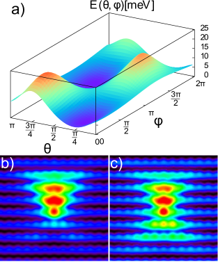
This model gives a good description of Mn in bulk GaAs but the effect of the cleavage surface is completely neglected. In fact it has been shown experimentallyÇelebi et al. (2010) that the wavefunction of a Mn near the (110) cleavage surface can be strongly affected by the strain from the surface relaxation. In the same paper, bulk tight binding calculations support the observation of a broken symmetry near the surface. The surface is taken into account by applying a uniform strain to the bulk model by shifting the Ga lattice with respect to the As lattice. The calculation results presented in that paper are the average of different Mn core spin orientations. In Fig. 1, the same results are presented but for individual Mn core spin orientations. Fig. 1 was unpublished in this form. A clear difference in LDOS can be observed when the Mn core spin changes its orientation from the hard axis to the easy axis.
In the paper by Strandberg et al. Strandberg et al. (2009) the reconstructed surface is taken into account for the calculation of the LDOS dependence of the Mn acceptor state on the Mn core spin orientation using a tight binding model which includes the exchange interaction, spin-orbit coupling and Coulomb interaction. This makes a direct comparison with X-STM experiments more justified and the results indeed show the same experimentally observed breaking of the symmetry of the wavefunction due to the near presence of the surface. In Ref. Strandberg et al., 2009 Mn acceptors in bulk GaAs (neglecting the surface) have also been considered. For Mn in bulk GaAs, the energy level of the Mn state calculated for different orientations of the Mn core spin shows a small magnetic anisotropy, in contrast to the results of Ref. Tang and Flatté, 2005, where no magnetic anisotropy was found for Mn in bulk. The easy axis in Ref. Strandberg et al., 2009 for the Mn core spin is oriented along the [001] direction whereas the hard axis is found to be lying in the (001) plane. The energy barrier between the hard axis and the easy axis is found to be 4.35 which is very small in comparison with the Mn binding energy in GaAs (113 ). At first, the presence of a magnetic anisotropy is surprising since there is no difference between the [001] and [010] or [100] directions in a Zinc-Blende crystal. The observed anisotropy can be explained by the use of periodic boundary conditions on finite clusters used in this paper Strandberg et al. (2009). The influence of other Mn atoms in the area may indeed introduce a small magnetic anisotropy and thus the observed magnetic anisotropy of Mn in bulk GaAs is artificial. Indeed, more recent calculations carried on out on much larger clusters show that the bulk magnetic anisotropy decreases monotonically with cluster size, down to a fraction of a meV for the largest clusters of 40,000 atoms Mahani and Canali (2011).
On the other hand, the calculation of the LDOS for Mn in bulk GaAs in Ref. Strandberg et al. (2009) shows good similarity with the calculations in Ref. Tang and Flatté (2005). The LDOS is found to be spreading in the direction perpendicular to the Mn core spin axis. The change in the shape of the LDOS is explained in terms of the px, py and pz character of the Mn acceptor hole. For different orientations of the Mn core spin, different components in the character dominate. When the Mn core spin direction is changed from [10] to [110] a drop in LDOS of 74 is observed at 4 atomic layers from the Mn position. This drop in LDOS is 25 when the core spin direction changes from [10] to [001], which is again in good agreement with the other calculations in Tang and Flatté (2005).
In Ref. Strandberg et al., 2009 similar calculations have been done for Mn in or below the GaAs (110) surface layer. For Mn at the surface and the first subsurface layer, a strong localization of the LDOS is observed and a magnetic easy axis in the [111] direction is found. The difference in LDOS for different Mn core spin orientations is negligible. Thus in an X-STM experiment, we expect to see no effect of the magnetic field on the Mn atoms very close to the surface.
For Mn atoms deeper below the (110) surface, the LDOS becomes more extended and the magnetic anisotropy shows a complex behavior for subsequent depths. However, from the fourth layer beneath the (110) surface and deeper, one can recognize the emergence of an easy plane with its normal in the [10] direction. The anisotropy energy is found to be at least 15 meV. Images of the (110) surface LDOS show that there is an increasing difference in LDOS for an increasing depth when the Mn core spin changes from the easy axis to the hard axis. For Mn atoms placed on fourth subsurface layers and deeper, the difference in LDOS varies between 40 and 82.
In summary, both Refs. Tang and Flatté, 2005 and Strandberg et al., 2009 have treated the behavior of the Mn acceptor hole LDOS in the (110) plane for different Mn core spin orientations. In both papers it is found that when the Mn core spin direction is changed from [10] to [110], a drastic change in the LDOS is taking place. The inclusion of the cleavage surface relaxation has resulted in similar observations.
The mechanism for the magnetic anisotropy in Refs. Tang and Flatté, 2005 and Strandberg et al., 2009 is the same — the presence of the surface, or strain, lowers the energy of an orbital wave function with quantization axis along a specific direction, and the spin-orbit interaction (which correlates the spin axis with the orbital axis) causes that preferred orbital direction to select a preferred spin axis. The effective energy associated with the correlation between spin axis and orbital axis is of the same order as the binding energy (Refs. Tang and Flatté, 2004, 2005; Strandberg et al., 2009 found it to be meV). At magnetic fields required to overcome the magnetic anisotropy energy the magnetic length is of order nm, which is three times larger than the effective Bohr radius of the acceptor ( nm). Therefore the overall distortion of the acceptor state wave function due to the direct effect of the magnetic field on the orbital wave function is small compared with the spin-orbit term. What is not certain, however, is whether the effect of the magnetic field on the acceptor state wave function can substantially change the magnetic anisotropy; this will be examined in Section V.
In an X-STM experiment, one can also check the results of these calculations by applying a magnetic field perpendicular and parallel to the (110) cleavage plane and by measuring the Mn contrast, which can change with a factor as high as 90. In the next section, we discuss the X-STM experiments that have been performed to observe the predicted effects.
III Experiments
A Mn doped layer of 500 thick was grown on a p-type GaAs substrate at high temperature with Mn concentrations of about 31019 . The experiments are performed with an Omicron Cryogenic STM operating at a base temperature of 2.5 K. A magnetic field vector can be applied with fields of up to 6 T in the z-direction only or max. 2 T in the z-direction together with max. 1 T in the x- and y-directions. The x-, y- and z-direction are indicated in figure 2a where 2 Mn atoms at different depths below the cleaved surface are visible.
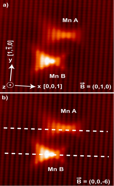
The magnetic field is indicated in the vector notation in units of T: =(,,).
From Ref. Çelebi et al. (2010), we estimate that Mn A is approximately 8 atomic layers
below the cleavage surface and that Mn B is at about 5 atomic layers below the cleavage surface.
In Strandberg et al. (2009), a change in contrast of 40 is predicted for a
Mn A at 8 layers below the cleavage surface when the Mn core spin changes from the
[110] direction to the [10] direction. For Mn B at 5 atomic layers beneath
the cleavage surface, a change of 60 is predicted when the Mn core spin direction
changes from the [110] direction to the [10] direction.
As can be seen from the comparison of figures 2a and 2b,
there is no change at all in the Mn contrast for both Mn atoms when the magnetic
field is changed from 1 T in the y direction to -6 T in the z-direction.
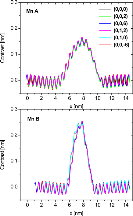
In figure 3, a more quantitative comparison is made by looking
at the contrast of the Mn atoms in different magnetic fields through the
dashed lines in figure 2b. Also in these plots, it can be seen that
for both Mn atoms, there is no difference at all in the contrast for different orientations of the magnetic field.
For Mn B, the plots for B=(0,1,0) and B=(0,0,-6) are slightly different from the rest
because of a small tip modification that has taken place.
The tip has become slightly less sharp in the scan direction (the [001] x-direction) and
this difference is noticed when sharper objects like Mn B are imaged.
Mn A has FWHM of about 4.5 in the scan direction,
while Mn B has a sharper feature with a FWHM of about 2.0 . The different FWHM of
the Mn features has been related to the depth below the GaAs surface Çelebi et al. (2010)
IV THEORETICAL MODEL
We model theoretically substitutional Mn impurities in GaAs following the procedure put forward in Ref. Strandberg et al., 2009. Our second-quantized tight-binding Hamiltonian for (Ga,Mn)As takes the following form:
| (1) |
where and are atomic indices that run over all atoms, runs over the Mn, and over the nearest neighbors of Mn atom . and are orbital indices and is a spin index. The first term in Eq. (1) contains the near-neighbor Slater-Koster tight-binding parametersSlater and Koster (1954); Papaconstantopoulos and Mehl (2003) that reproduce the band structure of bulk GaAsChadi (1977) and that are rescaledChadi (1978, 1979); Strandberg et al. (2009) when needed to account for the buckling of the (110) surface.
The second term implements the antiferromagnetic exchange coupling between the Mn spin (treated as a classical vector) and the nearest neighbor As -spins . The exchange coupling eV has been inferred from theory Timm and MacDonald (2005) and experiment Ohno (1998). As a result of this term the acceptor hole that is weakly bound to the Mn will become spin polarized. This model contains only and orbitals, and the effect of the Mn electrons is encoded in the exchange term.
Next, we include an on-site spin-orbit one-body term, where the renormalized spin-orbit splittings are taken from Ref. Chadi, 1977. Spin-orbit coupling will cause the total energy to depend on the Mn spin direction, defined by a collinear variation of .
The fourth term is a long-range repulsive Coulomb part that is dielectrically screened by the host material. To account in a simple way for weaker dielectric screening at the surface, the dielectric constant for a Mn on the surface is reduced from the bulk GaAs value 12 to 6 for the affected surface atoms. This crude choice is qualitatively supported by experimental results Teichmann et al. (2008); Lee and Gupta (2011).
The last term is a one-particle correction potential for the Mn central cell. This term is the least known and understood theoretically. It consists of on- and off-site parts, which influence the Mn ion and its As nearest neighbors respectively. The on-site Coulomb correction is estimated to be eV from the ionization energy of Mn. The off-site Coulomb correction affects all the nearest-neighbor As atoms surrounding the Mn ion and together with the exchange interaction, it reflects primarily the - hybridization physics and is the parameter that in the model primarily controls the binding energy of the hole acceptor state. The off-site Coulomb correction value is set by tuning the position of the Mn-induced acceptor level in the bulk to the experimentally observed positionSchairer and Schmidt (1974); Lee and Anderson (1964); Chapman and Hutchinson (1967); Linnarsson et al. (1997) at 113 meV above the first valence band level. The value thus obtained is eV. When the Mn impurity is on the GaAs surface, the value of is reduced to ensure that the position of the acceptor level is consistent with the value attained via STM spectroscopy.
The off-site Coulomb correction is in fact a repulsive potential for the electrons. If we use the bulk value (2.4 eV) for the surface, the acceptor level lies deep in the gap at 1.3 eV above the valence band, which means the acceptor wave function is now much more localized around the Mn than its bulk counterpart. In order to guarantee the experimentally observed position for the acceptor level, 0.85 eV Kitchen et al. (2006), we have to decrease this repulsive potential for the electrons, which causes the hole wave function to be less localized with a corresponding smaller binding energy.
The electronic structure of GaAs with a single substitutional Mn atom is obtained by performing a super-cell type calculation with a cubic cluster of a few thousands atoms and periodic boundary conditions in either 2 or 3 dimensions, depending on whether we are studying the surface or a bulk-like system. The surface of GaAs is simplified from both theoretical and experimental points of view, by the absence of large surface reconstruction. In order to remove artificial dangling-bond states that would otherwise appear in the band gap, we include relaxation of surface layer positions following a procedure introduced in Refs. [Chadi, 1978, 1979]. For more details the reader is referred to Ref. [Strandberg et al., 2009].
We would like to emphasize that the strength of the off-site Coulomb correction is the only important fitting parameter of the model, and its value is fixed once for all by the procedure described above. All the other parameters in Eq. 1 are either determined by theoretical considerations, or for the cases when this is not possible (e.g. short- range onsite potential) their values are extracted from experiment. In any case, they affect weakly the properties of the acceptor level. Once the parameters of the Hamiltonian of Eq. 1 are chosen in the way indicated above, the model has to be viewed as a microscopic description, with predictive power, of the properties of Mn impurities in GaAs surfaces and subsurfaces. In this sense the model of Ref. Strandberg et al., 2009 has been quite successful in capturing some of the salient features of the STM experiments Garleff et al. (2008, 2010), probing the Mn-dopant acceptor hole near the GaAs (110) surface. For example, it correctly describes the dependence of the acceptor binding energy Garleff et al. (2010) and the shape of the hole wave function Garleff et al. (2008) on the layer depth below the surface on which the magnetic dopant is positioned. The model also makes a prediction on how the magnetic anisotropy barrier for the Mn-impurity–hole magnetic complex changes as a function of the layer depth. These predictions can be indirectly checked by the magnetic-field studies that are the main scope of the present paper.
In order to study the response of the system to an external magnetic field, we introduce the Zeeman term
| (2) | |||||
where the first term runs over all and orbitals of all atoms, and the second term represents the coupling of the magnetic field with the magnetic moment of the Mn impurities, treated as a classical vector. Here is the Bohr magneton, , and we follow the incorrect but common convention that spins and magnetic moments are parallel to each other 111Because the electron charge is negative, magnetic moments and angular momentum are in fact oriented antiparallel to each other. In a magnetic field the energetically favorable direction of the magnetic moment is parallel to the field while the direction of the spin is antiparallel. Assuming that magnetic moment and angular momentum are parallel is strictly speaking incorrect but does not change the physics.. Therefore in the paper we will loosely refer to the direction of as the direction of the Mn magnetic moment.
V THEORETICAL RESULTS AND DISCUSSION
We start by analyzing the magnetic anisotropy properties for one Mn at the (110) GaAs surface layer and the immediate subsurface layers, and see how these are modified by the presence of an external magnetic field of a few Tesla. The magnetic anisotropy landscape as a function of for one Mn at the surface and the first 9 subsurfaces has been studied in detail in Ref. Strandberg et al., 2009. Typically the system has an uniaxial anisotropy with two minima separated by an energy barrier. We will refer to the direction of minimum energy as the easy direction and the one of maximum energy as the hard direction.
We first consider the case of one Mn impurity at the (110) surface. To facilitate the comparison with the case in which a magnetic field is present, we recalculated and plotted here anisotropy landscapes and LDOS in the absence of the magnetic field, originally published in Ref. Strandberg et al., 2009, using an improved code.
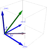
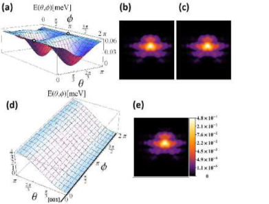
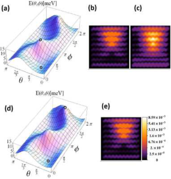
In Fig. 5(a) we plot the anisotropy energy landscape in the absence of the magnetic field, as a function of the angles and defining the direction of . The coordinate system used for this and the other plots in the paper has parallel to the [001] axis, parallel to [100], and parallel to [010]. See Fig. 4.
The anisotropy landscape displays two minima, identifying the easy direction [111], separated by an energy barrier of the order of 1 meV. Note that these tight-binding results of the magnetic anisotropy of a Mn at the (110) GaAs surface are consistent with recent first-principles estimatesIslam and Canali (2012). Panels (b) and (c) of Fig. 5 show the LDOS for the Mn acceptor state when the Mn spins point along the easy and hard direction respectively, determined from the landscape in (a). As discussed in Sec. II and shown clearly in the figures, the acceptor state wavefunction for a Mn on the surface is very localized around the impurity, and the dependence of the LDOS on the Mn spin orientation is negligible. The acceptor wavefunction, itself strongly anisotropic, seems to be completely decoupled from the orientation of the Mn magnetic moment.
Fig. 5(d) and (e) show the effect of a 6 T magnetic field on the anisotropy and LDOS respectively, when the field is applied in the hard direction of the anisotropy landscape in (a).
We can see that the magnetic field changes considerably the anisotropy landscape, which has now an easy axis at (the direction of the field). Note that in the presence of the field the anisotropy barrier has increased up to meV. The LDOS in Fig. 5(e) is now calculated for pointing along the new easy axis, determined by the magnetic field. Despite the strong change in the anisotropy landscape brought about by the magnetic field, the acceptor LDOS is essentially identical to the one calculated in the absence of the field, in agreement with the experimental results.
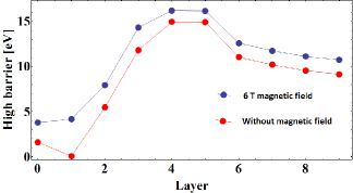
Before continuing our LDOS analysis, it is useful to consider how the anisotropy-energy barrier depends on the Mn-impurity depth from the (110) surface. In Fig. 6 we plot the largest value of the anisotropy energy barrier as a function of the subsurface layer index (layer 0 is the (110) surface). In general, in the absence of a magnetic field (red dots in the picture) the anisotropy barrier increases with Mn depth, reaching a maximum of meV for layers 4 and 5. It then starts to decrease and it should eventually reach a very small value corresponding to the case where the Mn is effectively in the bulk. For the finite clusters that we have considering here (20 layers in the z-direction), the anisotropy remains large also when the impurity is effectively in the middle of the cluster (corresponding to layer 9 from the surface). Bulk calculations on considerably larger clusters show that the anisotropy for impurities in the middle of the clusters does decrease to a fraction of one meVMahani and Canali (2011). For these larger clusters the magnetic anisotropy of the Mn positioned in on layers is expected to decrease a bit with cluster size. However the qualitative behavior of the first 7-8 layers shown in Fig. 6, and the corresponding numerical values of the magnetic anisotropy are controlled by the vicinity to the surface and as such should not depend strongly on cluster sizeMahani and Canali (2011).
Layer 1 (the first subsurface layer)is a special case in the sense that the anisotropy is very small, on the order of 0.1 meV. The first subsurface represents the cross over from the case in which the Mn is at the surface, with three nearest neighbor As, to a bulk-like environment characterized by four nearest neighbor As atoms. The properties of the acceptor level found in STM experiments for a Mn positioned on this subsurface are also quite anomalousLee and Gupta (2010). When a magnetic field of 6 T is applied along the hard direction (blue dots in Fig. 6) the anisotropy barrier increases by a couple of meV. The exception is again the first subsurface (layer 1), whose anisotropy is now completely controlled by the magnetic field and behaves in a similar way to the surface layer. The behavior of the first subsurface anisotropy landscape is shown explicitly in Fig. 7 (a), (d).
As for the case of a Mn atom placed at the (110) surface, the acceptor LDOS for a Mn on the first subsurface (see Fig. 7(b), (c) ) is completely insensitive to the direction of the Mn magnetic moment. Again a 6 T magnetic field, which is able to completely modify the magnetic anisotropy landscape and orient the Mn moment parallel to its direction, does not have any detectable effect on the acceptor wave function, as shown in Fig. 7(d).
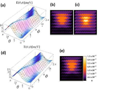
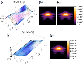
As the Mn is placed in successively deeper layers below the surface and the acceptor wavefunction becomes less localized around the impurity, the situation changes. In Figs. 8 and 9 we plot the anisotropy landscape and the acceptor LDOS for the fourth and fifth subsurface (layer 4 and 5 below the surface) respectively. As we discussed before, when the direction of the Mn moment is forced to point in the hard direction (panel (c) of Fig. 8) the LDOS around the Mn increases sensibly. The two cases, easy (panel b) and hard axis LDOS are now clearly distinguishable. Since the acceptor wavefunction is always normalized, an increase of the LDOS in the core region implies that the acceptor wavefunction is considerably more localized when the Mn magnetic moment points in the hard direction. On the other hand, in contrast to the surface and the first subsurface, the energy barrier in this case is considerably larger. A magnetic field of the order of those applied experimentally are now not strong enough to modify appreciably the anisotropy landscape. This can be seen by comparing panel (a) – no magnetic field – with panel (d), where magnetic field of 6 T is applied in the hard direction. Consequently, the direction of the easy axis is only slightly modified in the presence of a magnetic field, and as a result, the corresponding acceptor LDOS appears now very similar to the zero-magnetic field case [panel (b)]. This is again in agreement with the experiments presented in this paper.
As mentioned before, the experiments presented in Garleff et al. (2010) showed the energy level splitting of Mn in GaAs close to the cleavage surface. For a typical Mn position at 5th subsurface layer, a total splitting of 14 meV is found between the 3 peaks which are attributed to the different projections of the total momentum J=1 which is the result of anti-ferromagnetic coupling between the 5/2 Mn core spin and 3/2 Mn acceptor total angular momentum. In Fig. 9, it can be seen that the MAE is indeed about 15 meV which corresponds well with the findings in Garleff et al. (2010).
In Fig. 1, the MAE as calculated in another tight binding calculation (strained bulk GaAs) is about 23 meV. This is more than the 15 meV of the supercell calculations (Fig. 9) possibly because of the overestimated strain or its assumed uniformity.
We conclude that, although the LDOS of deep-subsurface Mn acceptors is in principle strongly dependent on the Mn magnetic moment direction, its actual manipulation with an external magnetic field is not suitable at field strengths presently used in experiment.
VI Conclusions
In conclusion, this work is the first systematic study of the effect of an external applied magnetic field on the acceptor properties of individual Mn impurities in GaAs. Specifically, we have investigated theoretically and experimentally the effect of an external magnetic field on the acceptor hole wavefunction and LDOS of Mn impurities placed near the (110) surface of GaAs. The acceptor LDOS is directly accessible via X-STM experiments.
The motivation of this study was in part provided by previous theoretical studies which predicted that the LDOS in some cases strongly depends on the orientation of the magnetic impurity magnetic moment. The theoretically model used in this analysis is essentially parameter-free, once the energy of the surface acceptor state is fixed to reproduce the experimental value.
Experimentally we find that there is no detectable difference in the STM images of the acceptor hole LDOS when a magnetic field up to 6 T is applied in several directions with respect to the crystal structure. To reconcile theory and experiment we have carried out a theoretical analysis of the magnetic anisotropy energy and acceptor hole wavefunction in the presence of a magnetic field. We have shown that for Mn impurities placed in deep sub-layers below the surface, the calculated magnetic anisotropy landscape is characterized by energy barriers of the order of 10-20 meV, which are only minimally affected by magnetic fields used in experiment. We estimate that one needs to employ much stronger fields (on the order of tens of Tesla) to modify significantly the anisotropy landscape and rotate the magnetic moment of the impurity. This estimate is based on the idea of manipulating a spin=5/2 object with g-factor=2 with an external field to overcome an energy barrier of 15 meV.
For impurities placed near the surface, the magnetic anisotropy is small enough to be considerably affected by a magnetic field of a few T. However, for this case the acceptor hole LDOS is much less sensitive to the orientation of the Mn magnetic moment. The combination of these two facts seem to explain the experimental finding that the the STM images of the acceptor hole wavefunction is essentially unaffected by an external magnetic field.
Our studies show that the Mn-dopant behavior close to the GaAs surface depends on the layer depth in a complex and highly non trivial way. These studies also suggest that it could be interesting to carry out a similar investigation for other magnetic dopants and other semiconductors. It might be possible that for some of these systems the acceptor wavefunction for a dopant near the surface be more delocalized and amenable to an easier manipulation by a static magnetic field, displaying the effects originally predicted for Mn in GaAs. It should also be possible to use resonant techniques, such as those commonly used in electron spin resonance and ferromagnetic resonance, to map out the anisotropy landscape presented here for Mn near the GaAs surface. Finally, excitations of the spin that would correspond to the quantized spin in the anisotropy landscape here should be visible in inelastic tunneling spectroscopy. Thus these new predictions do not mean that Mn spin dynamics is impossible to see near the surface of GaAs, merely that it is more challenging to observe.
Acknowledgements.
We would like to thank W. van Roy and Z. Li for the Mn doped GaAs samples which they have provided and A. H. MacDonald for several useful discussions. We would like to thank also B. Bryant for substantial experimental support during the X-STM measurements. This work was supported by STW-VICI Grant No. 6631. We acknowledge support from the Engineering and Physical Sciences Research Council (EPSRC) through grants EP/D063604/1 (PS, SRS, NJC, and CFH) and EP/H003991/1 (SRS). This work was also supported in part by the Faculty of Natural Sciences at Linnaeus University, by the Swedish Research Council under Grant Numbers: 621-2007-5019 and 621-2010-3761 and by the Nordforsk research network: 08134, Nanospintronics: theory and simulations.References
- Karlik et al. (1982) I. Karlik, I. Merkulov, D. Mirlin, L. Nikitin, V. Perel, and V. Sapega, Sov. Phys. Solid State 24, 2022 (1982).
- Dietl et al. (2001) T. Dietl, H. Ohno, and F. Matsukura, Phys. Rev. B 63, 195205 (2001).
- Jungwirth et al. (2005) T. Jungwirth, K. Y. Wang, J. Mašek, K. W. Edmonds, J. K nig, J. Sinova, M. Polini, N. A. Goncharuk, A. H. MacDonald, M. Sawicki, A. W. Rushforth, R. P. Campion, L. X. Zhao, C. T. Foxon, , and B. L. Gallagher, Phys. Rev. B 72, 165204 (2005).
- Myers et al. (2008) R. Myers, M. Mikkelsen, J.-M. Tang, A. Gossard, M. Flatté, and D. Awschalom, Nature Materials 7, 203 (2008).
- Kudelski et al. (2007) A. Kudelski, A. Lemaitre, A. Miard, P. Voisin, T. Graham, R. Warburton, and O. Krebs, Phys. Rev. Lett. 99, 247209 (2007).
- Léger et al. (2006) Y. Léger, L. Besombes, J. Fernández-Rossier, L. Maingault, and H. Mariette, Phys. Rev. Lett. 97, 107401 (2006).
- Fuchs et al. (2011) G. Fuchs, G. Burkard, P. Klimov, and D. Awschalom, Nature Physics 7, 789 (2011).
- Yakunin et al. (2004) A. M. Yakunin, A. Y. Silov, P. M. Koenraad, W. V. Roy, J. D. Boeck, J.-M. Tang, and M. E. Flatté, Phys. Rev. Lett 92, 216806 (2004).
- Tang and Flatté (2004) J.-M. Tang and M. Flatté, Phys. Rev. Lett. 92, 047201 (2004).
- Yakunin et al. (2007) A. M. Yakunin, A. Y. Silov, P. M. Koenraad, J.-M. Tang, M. E. Flatté, J.-L. Primus, W. V. Roy, J. D. Boeck, A. M. Monakhov, K. S. Romanov, I. E. Panaiotti, and N. S. Averkiev, Nat. Mater. 6, 512 (2007).
- Çelebi et al. (2010) C. Çelebi, J. K. Garleff, A. Y. Silov, A. M. Yakunin, P. M. Koenraad, W. V. Roy, J.-M. Tang, and M. E. Flatté, Phys. Rev. Lett. 104, 086404 (2010).
- Tang and Flatté (2005) J.-M. Tang and M. E. Flatté, Phys. Rev. B 72, 161315 (2005).
- Strandberg et al. (2009) T. O. Strandberg, C. M. Canali, and A. H. MacDonald, Phys. Rev. B 80, 024425 (2009).
- Garleff et al. (2010) J. Garleff, A. Wijnheijmer, A. Silov, J. van Bree, W. V. Roy, J.-M. Tang, M. E. Flatté, and P. Koenraad, Phys. Rev. B 82, 035303 (2010).
- Grinolds et al. (2011) M. S. Grinolds, P. Maletinsky, S. Hong, M. D. Lukin, R. L. Walsworth, and A. Yacoby, Nat. Phys 7, 687 (2011).
- Kitchen et al. (2006) D. Kitchen, A. Richardella, J.-M. Tang, M. E. Flatté, and A. Yazdani, Nature 442, 436 (2006).
- Lee and Gupta (2011) D.-H. Lee and J. A. Gupta, Nano Lett. 11, 2004 (2011).
- Schneider et al. (1987) J. Schneider, U. Kaufmann, W. Wilkening, M. Baeumler, and F. Köhl, Phys. Rev. Lett. 59, 240 (1987).
- Mahani and Canali (2011) M. R. K. Mahani and C. M. Canali, Unpublished Results (2011).
- Slater and Koster (1954) J. C. Slater and G. F. Koster, Phys. Rev. 94, 1498 (1954).
- Papaconstantopoulos and Mehl (2003) D. A. Papaconstantopoulos and M. J. Mehl, J. Phys.: Cond. Mat. 15, R413 (2003).
- Chadi (1977) D. J. Chadi, Phys. Rev. B 16, 790 (1977).
- Chadi (1978) D. J. Chadi, Phys. Rev. Lett. 41, 1062 (1978).
- Chadi (1979) D. J. Chadi, Phys. Rev. B 19, 2074 (1979).
- Timm and MacDonald (2005) C. Timm and A. H. MacDonald, Phys. Rev. B 71, 155206 (2005).
- Ohno (1998) H. Ohno, Science 281, 951 (1998).
- Teichmann et al. (2008) K. Teichmann, M. Wenderoth, S. Loth, R. G. Ulbrich, J. K. Garleff, A. P. Wijnheijmer, and P. M. Koenraad, Phys. Rev. Lett. 101, 076103 (2008).
- Schairer and Schmidt (1974) W. Schairer and M. Schmidt, Phys. Rev. B 10, 2501 (1974).
- Lee and Anderson (1964) T. Lee and W. W. Anderson, Solid State Commun. 2, 265 (1964).
- Chapman and Hutchinson (1967) R. A. Chapman and W. G. Hutchinson, Phys. Rev. Lett. 18, 443 (1967).
- Linnarsson et al. (1997) M. Linnarsson, E. Janzen, B. Monemar, M. Kleverman, and A. Thilderkvist, Phys. Rev. B 55, 6938 (1997).
- Garleff et al. (2008) J. K. Garleff, C. Çelebi, W. van Roy, J.-M. Tang, M. E. Flatté, and P. M. Koenraad, Phys. Rev. B 78, 075313 (2008).
- Note (1) Because the electron charge is negative, magnetic moments and angular momentum are in fact oriented antiparallel to each other. In a magnetic field the energetically favorable direction of the magnetic moment is parallel to the field while the direction of the spin is antiparallel. Assuming that magnetic moment and angular momentum are parallel is strictly speaking incorrect but does not change the physics.
- Islam and Canali (2012) M. F. Islam and C. M. Canali, Phys. Rev. B 85, 155306 (2012).
- Lee and Gupta (2010) D. H. Lee and J. A. Gupta, Science 330, 1807 (2010).