Resonant scattering and diffraction beamline P09 at PETRA III
Abstract
The resonant scattering and diffraction beamline P09 at PETRA III is designed for X-ray experiments requiring small beams, energy tunability, variable polarization and high photon flux. It is highly flexible in terms of beam size and offers full higher harmonic suppression. A state of the art double phase retarder setup provides variable linear or circular polarization. A high precision Psi-diffractometer and a heavy load diffractometer in horizontal Psi-geometry allow the accommodation of a wide variety of sample environments. A 14 T cryo-magnet is available for scattering experiments in magnetic fields.
I Introduction
P09 is optimized for resonant and non-resonant elastic scattering and diffraction experiments in the tender to hard X-ray range. Two diffractometers are located in two different experimental hutches: one for standard sample environments such as small cryostats or furnaces and another one for heavy sample environment setups. A 14 T DC magnet is also available. It is equipped with a variable temperature insert (VTI) and an optional 3He probe. In a third experimental hutch, beamline P09 hosts the hard X-ray photo-electron spectroscopy (HAXPES) station. This paper will focus exclusively on the resonant scattering and diffraction (RSD) stations.
The beamline is dedicated to resonant X-ray diffraction (RXD) experiments, in which the scattering cross section is strongly polarization dependent. However, various scattering and diffraction experiments in need of high photon flux, variable energy, variable polarization, focused beam are also possible. This includes investigation of reflectivities or superlattice reflections as a function of temperature, electric or magnetic fields in bulk samples, thin films or multilayer systems using linear or circular polarization, as well as in-situ characterization of sample growth in heavy chambers. With the highly focused X-ray beam, diffraction experiments from small single crystals or single domains within a larger multi-domain sample are possible.
The RXD technique is nowadays widely used in various fields Vettier (2012) and has been applied extensively to the investigation of electronic order in solids Beale et al. (2012). By tuning the X-ray energy close to an absorption edge, virtual multipole transitions are induced and the scattering process becomes sensitive to the intermediate states into which the core electrons are excited. From this a strong sensitivity to local environments and asymmetries in the electron distribution arises which can have various origins, such as charge, spin or multipolar order and can give rise to diffracted intensity at structurally forbidden positions in reciprocal space or an enhancement of weak magnetic reflections.
The anisotropic tensor of susceptibility (ATS) Dmitrienko (1983) describes the polarization dependent nature of the diffracted intensities at forbidden reflections at the absorption edges. ATS scattering originally was applied exclusively to the investigation of purely structural anisotropies. Independent from that, magnetic RXD was discovered Gibbs et al. (1988), which yields, dependent on the type of transitions, strong resonant enhancement of the weak magnetic intensities of magnetic superlattice reflections. The sensitivity of RXD to magnetic order in the following years was extensively used to investigate magnetic ordering phenomena as a function of temperature, external magnetic field or pressure as a complementary probe to neutron diffraction. The element sensitivity of XRD was used to distinguish between contributions of different elements to the magnetic ordering. ATS scattering was later applied to orbital and charge ordering Murakami et al. (1998) and since then also to the investigation of higher multipolar order terms.
From the original description of the resonant magnetic cross section Blume (1985) until now, theory has advanced considerably and the description of the different resonant diffraction phenomena has been greatly unified by the so-called multipole expansion of the electric and magnetic state of matter Di Matteo (2012). This provides a wide field of ordering phenomena to be investigated.
At P09, all requirements for state of the art resonant and non-resonant scattering experiments are met, which include energy tunability, the possibility of vertical as well as horizontal scattering, manipulation of incident polarization, analysis of the polarization of the diffracted beam, variable beam focus and higher harmonic suppression in the whole energy range. The beamline covers the absorption edges in the energy range from 2.7 to 24 keV, which include the 4d L-edges (Mo, Ru, Rh, …), the 5f M-edges (U), the 4f L-edges, the 3d K-edges and the 5d L-edges. For experiments at low photon energies, P09 is virtually windowless except for a 20 m diamond window which separates the ring from the beamline vacuum.
II Storage ring, Undulator and Front-end
Beamline P09 is located at the 3rd generation synchrotron source PETRA III at DESY, which became operational in 2009 Balewski et al. (2004). The PETRA III storage ring has a circumference of 2.3 km. It accommodates 9 straight sections corresponding to 9 sectors in the experimental hall covering 1/8th of the ring circumference. In total, 14 beamlines are installed using canted 2 m undulators with a canting angle of 5 mrad in 5 sectors, 5 m undulators in 3 sectors and a m undulator in the first sector.
PETRA III sets itself apart from other synchrotron sources due to its low horizontal emittance of 1 nm rad. The lower emittance directly translates into a reduced horizontal photon source size and beam divergence and into a high brilliance for all beamlines. PETRA III operates at 6.084 GeV ring energy. The ring current is injected in top-up mode with 480 (eventually 960) bunch filling pattern and 100 mA ring current in normal operation. Reduced bunch modes with 60 and 40 bunches are used for timing experiments.
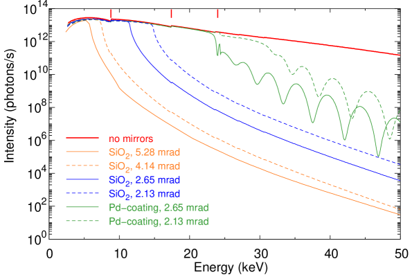
P09 is located at sector 6 of the PETRA III experimental hall. It shares the sector with beamline P08, the High Resolution Diffraction Beamline Seeck et al. (2012). The two beamlines are using two separate undulators canted by an angle of 5 mrad. The undulators are placed in a high- section of the storage ring, where the calculated rms photon source sizes and divergences at 8 keV are m2 (HV) and rad2 (HV), respectively. At P09, a 2 m long U32 spectroscopy undulator is used with a period length of =31.4 mm and a peak field of B0=0.91 T Barthelmess et al. (2008). It generates a continuous energy spectrum via gap scanning with a transition from 1st to 3rd harmonic at an energy of 8.8 keV as shown on Fig. 1. The lowest gap size is 9.8 mm allowing for a minimum energy of 2.7 keV at the first harmonic. Water-cooled power slits in the beamline front-end are used to shape the beam and to reduce the heat-load by cutting off the low energy halo around the central cone.
III Beamline optics
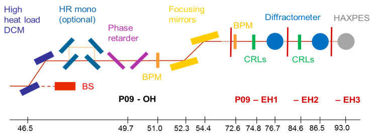
In Fig. 2 we show the different optical elements at P09 and their distances from the source. The optics hutch P09-OH starts at 45.2 m. The first component is the high heat-load double-crystal fixed-exit monochromator (DCM) (FMB Oxford, Osney Mead, UK) located at 46.5 m. The vertical offset of the monochromatic beam relative to the white beam is 21 mm. A horizontal translation of the whole monochromator tank perpendicular to the beam allows switching between Si(111) or Si(311) crystal pairs. Both pairs are cryogenically cooled with liquid N2. Because of the smaller Darwin width of the Si(311) Bragg reflection, the energy resolution can be improved by almost a factor 5 when using Si(311) instead of Si(111) at the expense of a factor 5 in photon flux. The energy bandwidth is and or in absolute units 1 (0.5) eV and 0.2 (0.1) eV, respectively, at 8 (4) keV. The lowest energy at which Si(311) crystal pairs can be used is 5.2 keV, corresponding to a maximum monochromator angle of currently 46.7∘. Quad beam position monitors (QBPMs) (FMB-Oxford) at 51 m in P09-OH and at 72.6 m in the 1stexperimental hutch (P09-EH1) equipped with 0.5m Ni and Ti foils can be used to stabilize the beam position as well as its direction by adjusting position and pitch of the second monochromator crystal. Downstream of the monochromator at 49.7 m, the double phase-retarder setup can be used to vary the polarization of the incident monochromatic beam. It is followed by two 1 m long vertically reflecting mirrors at 52.3 and 54.4 m used for focusing and higher harmonics rejection. The position of the sample at the center of rotation of the diffractometers is at 76.7 m in P09-EH1 and at 86.5 m in P09-EH2. The vacuum at the optical components is maintained at pressures below mbar up to the 20 m thick diamond X-ray window (Diamond Materials, Freiburg) at the entrance to P09-EH1. In P09-EH1, 3 m in front of the sample position, a 3rd 300 mm long quartz mirror is available to further suppress higher harmonics in the low energy regime below 4 keV. Additional focusing at fixed energy can be achieved using compound refractive lenses (CRLs) Lengeler et al. (1999). In the following, the double phase-retarder setup, the double mirror setup and the CRL setup are explained in more detail.
III.1 Phase retarder
Magnetic structures are usually determined through the investigation of the scattered intensity as a function of the azimuth. However such measurements imply a rotation of the sample around the scattering vector together with the whole sample environment (i.e. cryostat or magnet) over a large angular range of the azimuth at different scattering vectors which is not always possible. Moreover, different grains of the sample often scatter at different azimuthal angles and thus make such measurements extremely difficult. These difficulties can be overcome using polarization scans i.e. the generation of incident linearly polarized X rays at a variable angle of the linear polarization plane around the beam direction and the analysis of the dependence on of the Stokes parameters and of the diffracted signal from a sample Blume and Gibbs (1988); Detlefs et al. (2012). After its first implementation at beamline ID20 at ESRF Paolasini et al. (2007), this method has become a routine requirement due to its versatility. Polarization scans allow disentangling between different contributions to the resonant scattering cross-section as was first shown by Mazzoli et al.Mazzoli et al. (2007). For magnetic resonant and non-resonant scattering experiments, full polarization scans are used to determine the magnetic moment orientation Johnson et al. (2008). In addition, circular polarization with the possibility of fast switching between left and right circular polarization is of great importance, since it can be used to determine properties of chiral magnetic structures Fabrizi et al. (2009). A sketch of a diffraction experiment with phase-plates and polarization analyzer is shown in Fig. 4.

Circular and rotated linear polarization can be obtained using quarter wave plates (QWP) and half wave plates (HWP), respectively. In the hard x-ray regime, QWP and HWP conditions can be obtained by using perfect crystals and slightly detuning them from the ideal Bragg condition Giles et al. (1994). The actual phase shift depends on the deviation angle from the Bragg position.
The double phase-retarder setup is mounted in a UHV vacuum tank and consists of two Eulerian cradles, and separated by 340 mm (Huber Diffraktionstechnik, Rimsting, Germany) (Fig. 3). On each of them two high resolution rotation stages are mounted opposite to each other acting as and circles. The -circles are equipped with a 10 mm translation making it possible to switch between 3 phase-retarding plates. A piezo-actuator below the plates allows oscillation with frequencies of up to 40 Hz for fast switching the helicity of circular polarization. On the stages, passivated implanted planar silicon (PIPS) diodes (Canberra) are located which monitor the diffracted intensity. The two Eulerian cradles are mounted on separate - and -stages. Their axes of rotation are aligned towards each other within a precision of better than 0.1∘. The rotation axis of one of them can be aligned precisely along the beam axis using yaw and pitch rotations. As a result, Bragg peaks remain in diffraction condition within arcsec when is rotated between 0 and ∘ and within 10 arcsec when is rotated between 0 and ∘.

Currently, two identical sets of synthetic type Ib diamond phase plates are mounted on the two and stages: two diamond plates of 100 and 200 m thickness with the [111] direction as surface normal and one diamond plate of 400 m thickness with the [100] direction as surface normal. Each plate is oriented such that the (111) and (1̄1̄1) reflections can be set in diffraction condition, which allows an extension of the usable energy range of each plate owing to the different glancing angles onto the (111) planes. In Fig. 5 the deviation angles from the Bragg position necessary to achieve the quarter wave plate condition (QWP) are shown for the 400 m (100) plate for two different glancing angles. Depending on which plate is used and which reflection is set diffracting, the plates are either used in the asymmetric Laue geometry or the symmetric Bragg geometry. The present set of diamond phase plates allows manipulation of the polarization of the incident X rays in the energy range between 3.5 and 8 keV.
Linear polarization scans are carried out using either one single HWP or two QWPs in series and rotating their scattering planes around the X-ray beam. Scagnoli et al. have shown Scagnoli et al. (2009) that using two QWPs in series in a 90∘ geometry, i.e. , allows compensation for depolarisation effects due mostly to the energy spread, while two QWPs in series in an antiparallel geometry, i.e. , compensate for depolarization effects due to the angular divergence. The angular divergence is very low at P09 and can be neglected. The energy spread on the other hand contributes an angular spread of more than 10 arcsec at energies below 9 keV, which is non negligible. The combination of two QWPs in the 90∘ geometry results in a 5 to 10% higher degree of linear polarization than (i) using one single HWP of half the total effective thickness Francoual et al. (2013) and (ii) using two QWPs in the parallel geometry, i.e. Scagnoli et al. (2009); Okitsu et al. (2001); Inami et al. (2013). An example of the direct beam polarization properties for two QWPs in series in the 90∘ geometry at the Mn K-edge energy is given in the inset of Fig. 5. The degree of linear polarization is 96.8(1.7)% in average.
It is foreseen in the near future to change to synthetic type IIa diamond plates for which QWP deviation angles as low as 20 arcsec can be used Scagnoli et al. (2009); Okitsu et al. (2001). Right now, the minimum deviation angles for the type Ib diamond plates used at P09 are 40 arcsec Francoual et al. (2013). Type IIa synthetic diamonds produced by the temperature gradient growth method at high temperature and high pressure are better quality than type Ib diamonds regarding lattice strain and crystal defect structures as well as regarding the amount of impurities and inhomogeneities Härtwig and Connell (2005). A previous study has shown that while synthetic type IIa diamonds show a typical broadening of the Darwin width of up to 5 arcsec over the whole crystal, synthetic type Ib diamonds show a width broadening of up to 20 arcsec Sumiya et al. (1997). A direct benefit will be the larger usable energy range of each crystal and a higher transmission rate at the lowest deviation angles. The type IIa diamond phase-plates will cover the energy range from 3.2 to 14 keV. A set of 10 m thin silicon phase plates will cover the energy range between 2.7 and 3.2 keV Goulon et al. (1996); Bouchenoire et al. (2012). An additional double phase-retarder setup allowing operation of two plates in series in the 90∘ geometry has been designed to fit at the optical table in P09-EH1 in front of the transfocator and the beam monitor for variable polarization in P09-EH1 and P09-EH2. This device is not in vacuum and will accommodate the thick type IIa diamond plates (m).
III.2 Mirrors
The mirrors in P09-OH are 1 m long and 130 mm wide fused silica (SiO2) mirrors with averaged slope errors over 800 mm length of rad (rms) sagittal, rad (rms) meridional and surface roughness nm (rms). In order to preserve parallel beam, the first mirror deflects vertically up, the second vertically down. The first mirror (Pilz-Optics, Oberkochen, Germany), has two cylinders with sagittal radii of curvature of mm and a flat section in between the cylinders. Half of the flat section and one cylinder are coated with 40 nm palladium. The second mirror (SESO, Aix-en-Provence, France) has one cylinder with a sagittal radius of curvature mm and two flat sections at the sides, where one of them is coated with palladium. In addition, the second mirror is equipped with a bender allowing meridional radii of curvature down to km for vertical focusing. By combining different settings of the two mirrors as shown in Table 1, it is possible to efficiently suppress higher harmonics in the energy range from 6 to 24 keV in P09-EH1 and 7 to 32 keV in P09-EH2 and at the same time to focus the beam into P09-EH1, P09-EH2 and P09-EH3 by varying the glancing angle.
| Focus pos. | Coating | GA | Cutoff | |||
| (m) | (mm) | (mm) | (km) | mrad | (keV) | |
| unfocused | SiO2 | flat | flat | flat | variable | variable |
| 76.7 | SiO2 (Pd) | 88 | flat | 11.9 | 2.65 | 11.5 (24) |
| SiO2 | flat | 167 | 6.0 | 5.28 | 5.7 | |
| 86.5 | SiO2 (Pd) | 88 | flat | 19.4 | 2.13 | 14.3 (31) |
| SiO2 | flat | 167 | 9.7 | 4.14 | 7.3 | |
| 90.1 | SiO2 (Pd) | 88 | flat | 22.8 | 2.00 | 15.1 (32) |
| SiO2 | flat | 167 | 11.1 | 3.90 | 7.9 | |
| 93.0 | SiO2 (Pd) | 88 | flat | 23.1 | 1.95 | 15.7 (34) |
| SiO2 | flat | 167 | 12.2 | 3.70 | 8.3 |
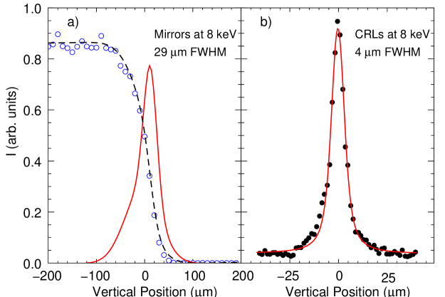
The mirrors are placed in separate UHV chambers. Yaw and pitch rotations and the translations perpendicular to the beam are externally applied to the whole chamber. The pneumatic bender is also external and the bending mechanically transferred into the chamber to the mirror through bellows. The focus size of the mirror reflected beam at the sample position in P09-EH1 is m (FWHM). A vertical knife-edge scan over the focused beam at the sample position in P09-EH1 is shown in Fig. 6a. The vertical width corresponds to a local meridional slope error rad (rms) showing the high quality of some significant mirror regions.
Calculated reflected intensities as function of energy of the different optical surfaces at different glancing angles are shown in Fig. 1. Because of the fixed distance between the mirrors, the beam height varies with the glancing angle, which means that the components after the mirrors have to be adjusted in height accordingly. After both mirrors, removable CVD diamond screens are located for beam alignment. The intensity of the mirror reflected beam at the sample position was determined at 8 keV to be photons/s using a calibrated photo-diode. This corresponds well to the calculated value.
The high incident flux is very important when phase plates or CRLs are used in front of the sample, since these reduce the incident flux considerably and flux hungry experiments such as non-resonant magnetic scattering would not be possible otherwise. However, great care has to be taken for experiments at low temperatures, since beam heating due to the high photon flux on the sample may affect the sample temperature considerably. Depending on the type of sample (metal, insulator) and the temperature range, a reduction of the incident beam intensity using attenuators in front of the sample might be necessary.
III.3 Micro focusing with compound refractive lenses
A movable in-vacuum lens changer (transfocator) is positioned in P09-EH1 or in P09-EH2 at m in front of the sample position. The transfocator consists of eight pneumatically actuated assemblies of CRLs varying in number and radius in order to allow focusing between 2.7 and 24 keV. It is mounted on motorized pitch and yaw rotations and x,z translations to align the optical axis of the CRLs parallel to the beam. It can also be translated by 300 mm along the beam for fine tuning of the focal point. The beam is pre-focused to 90.1 m from the source by the mirrors (glancing angle 2.0 or 3.9 mrad) in order to adjust the beam size to the 0.9 mm aperture of the CRLs. The beam is then refocused to the sample position by the CRLs resulting in a demagnification factor of about 8:1. Focal sizes of 4 m vertical and 50 m horizontal (FWHM) are achieved, as is shown in Fig. 6b, which should be compared to calculated values of 4 m vertical and 20 m horizontal. The efficiency for the focusing decreases with decreasing energy. While at 8 keV, the intensity loss is about a factor of 3, the overall intensity loss between unfocused and focused beam is increasing to factors of 20 at 3.5 keV and 25 at 3 keV mainly due to small impurities in the Be-lenses.
IV First experimental hutch (EH1) and 6-circle diffractometer
The first optical element in P09-EH1 is a QBPM with the same specifications as the one in the optics hutch. A UHV compatible high precision slit system just after the QBPM is used to define the beam Dommach et al. (2007). Following the slit system, a moveable CVD diamond screen is located. A 20 m diamond window with an opening of 3 mm, which is mounted in a CF-flange, separates the ring vacuum from the beamline vacuum. The QPBM, the slit system, the diamond screen and the diamond window are mounted on a granite table equipped with a horizontal and vertical translation to align them in the beam. An in-line electron Time of Flight (eToF) polarization monitor using photo-electrons from a gas target will be positioned on the same table in the near future Ilchen et al. (2009). This device will allow online monitoring of the incident polarization during polarization manipulation of the incident beam using the phase retarder setup.

Downstream from the granite table a m2 optical table is positioned on which the vacuum beam path with different components is mounted. A mounting system based on Newport X95 rails and carriers and KF40 flanges allows a very flexible modification of the arrangement of components. All components are designed to operate under vacuum down to 10-6 mbar. The equipment available on the optical table are the additional silica mirror and the transfocator. A beam monitor is positioned after the transfocator. For the beam monitor, a motorized translation is used to insert different thicknesses of glassy carbon foils in the beam (20, 60 and 100m). The foils are rotated by 45∘ both towards the beam and the ring plane. Two PIPS diodes with acceptance angles of about 10∘ positioned apart are used to monitor the intensities scattered horizontally and vertically. The monitor is extensively used to determine the QWP and HWP positions of the phase plates. The next component is an absorber box. Using pneumatic actuators, 12 different foils can selectively be inserted into the beam path, attenuating the beam up to at least 10 orders of magnitude in the whole energy range of 2.7- 30 keV. The last component before the diffractometer is an in-vacuum slit system (JJ-Xray A/S, Kgs. Lyngby, Denmark) followed by a 100 m thick Be-window.
| Motor | Range | Accur. | SOC | comment |
|---|---|---|---|---|
| (deg) | (arcsec) | () | ||
| / | 0.18 | 30 | vertical | |
| / | 0.36 | 30 | vertical | |
| 0.18 | 25 | horizontal | ||
| /111dependent on position of | 0.36 | 60 | horizontal | |
| 0.36 | 15 | without cryostat | ||
| 30 | with cryostat | |||
| 0 - 360 | 0.18 | 5 |
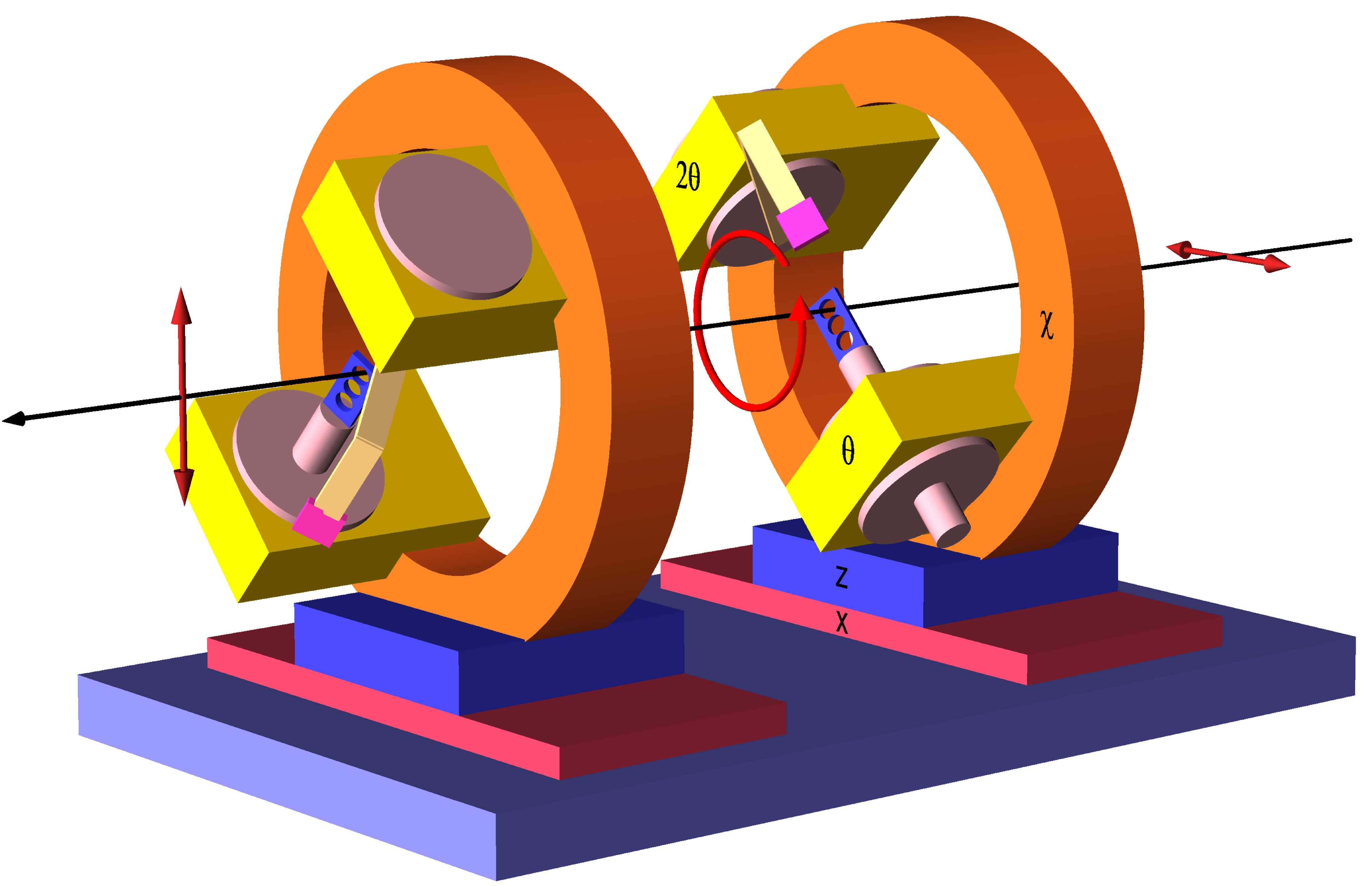
The main instrument in P09-EH1 is a high precision “4S+2D” 6-circle diffractometer (Huber Diffraktionstechnik) equipped with 4 circles for the sample (, , , ) and 2 for the detector (, ) (Fig. 7), all circles being independent. It allows both, vertical and horizontal diffraction. The -circle has an opening of 15 cm on the top, allowing for large vertical scattering angles. The cradle is equipped with the Huber 512.12M motorized xyz-cryostat carrier permitting a full 360∘ rotation. The sample stage can sustain up to 12 kg load. The reinforced detector arm consists of two motorized linear translation stages separated vertically by an angle of 25∘. The point detector setup with beam collimation and analyzer and the 2D detector are both mounted simultaneously, as shown in Fig. 7. The diffractometer is standing on a xz-table with a mm vertical and mm horizontal translation and a pitch of ∘. The angular ranges along with spheres of confusion for the different circles are shown in Table 2.
The following closed-cycle cryostats are available at P09: a 4 to 450 K ARS DE-202SG cryocooler (8 K base temperature on sample), a 6 to 800 K ARS CS-202AG cryocooler, a 1.7 to 300 K ARS DE-302 cryocooler (3 K base temperature at sample in the absence of exchange gas) and a vibration free 4 K Cooltran He-flow cryostat. The cryostats are limiting the angular range as shown in Table 2. They are equipped with Be-domes: an outer vacuum dome with wall thickness of 0.5 mm (D1) and a second dome acting as heat shield with wall thickness of 0.38 mm (D2). A third Be dome for exchange gas with a wall thickness of 0.38 mm (D3) is available for all cryostats. For low energy experiments, the external dome can be replaced by a windowless vacuum shroud to reduce absorption, which becomes relevant for energies below 4 keV (see inset of Fig. 7). At 2.8 keV, the intensity gain, when omitting the outer dome, amounts already to a factor of 10 for both the incident and diffracted beam as shown in Table 3. The windowless vacuum shroud has an angular range of two times 50 degrees. The range in is ∘. An azimuthal rotation is possible through the double O-ring coupling at the cryostat.
| Be (mm) | 8 keV | 6 keV | 4 keV | 2.8 keV | Configuration |
|---|---|---|---|---|---|
| 0.76 | 0.71 | 0.32 | D2 | ||
| 1.76 | 0.71 | 0.46 | 0.07 | D1, D2 | |
| 1.52 | 0.51 | 0.11 | D2, D3 | ||
| 2.52 | 0.61 | 0.33 | 0.02 | D1, D2, D3 | |
| 4.0 | 0.45 | 0.18 | Magnet | ||
| 6.0 | 0.31 | 0.07 | M., 3He-ins. |
On the detector arm, a Huber tube cross slit system 3002.60.M followed by a Huber cross slit system 3002.70.M are mounted to define the beam path between sample and detector. The connection to the polarization analyzer stage is done using a double O-ring coupling in order to allow an in-vacuum rotation of the complete analyzer stage around the scattered beam axis (-rotation) and a complete in-vacuum beam path starting at the Kapton window behind the sample up to the detector. The range of is 0 to -150 degrees. The analyzer crystal is mounted with the analyzer Bragg angle of towards the diffracted beam. The beam diffracted by the analyzer is recorded by the detector positioned at a scattering angle . The analyzer crystals are attached to the goniometer using kinematic mounts allowing for a fast change of the crystals. The height and roll of the analyzer crystals can be adjusted using Attocube piezo stages. A selection of the analyzer crystals available at the beamline together with most relevant absorption edges is shown in Table 4. A Huber 2-circle goniometer 415 can be mounted on the 2-theta arm instead of the polarization analyzer stage for experiments requiring higher resolution.
Cyberstar NaI-scintillation detectors and APD-detectors with ESRF-type amplifiers are available as point detectors at P09 (FMB-Oxford). An energy-dispersive silicon-drift VORTEX EX90 detector (SII NanoTechnology USA, Northridge, CA, USA) with 25 m Be window is used as a fluorescence detector. A Pilatus 300k 2D pixel detector (Dectris, Baden, Switzerland) is also available at the beamline.
| Crystal | (h k l) | d (Å) | E (90∘) (keV) | Absorption edges |
|---|---|---|---|---|
| Graphite | (0 0 2) | 3.358 | 2.61 | Mo(L2),Ru(L3) |
| TbMnO3 | (0 2 0) | 2.928 | 2.99 | Ru(L2) |
| Au | (1 1 1) | 2.338 | 3.75 | U(M4, M5) |
| Cu | (1 1 1) | 2.084 | 4.21 | |
| Graphite | (0 0 4) | 1.679 | 5.22 | V(K) |
| Mo | (2 0 0) | 1.574 | 5.57 | Ce(L3) |
| Al | (2 2 0) | 1.432 | 6.12 | Cr(K), Pr(L3), Nd(L3) |
| Cu | (2 2 0) | 1.276 | 6.84 | Mn(K), Fe(K), Eu(L3), |
| Nd(L2), Sm(L3) | ||||
| Au | (2 2 2) | 1.169 | 7.50 | Tb(L3), Sm(L2) |
| Graphite | (0 0 6) | 1.119 | 7.83 | Dy(L3), Gd(L2) |
| Cu | (2 2 2) | 1.042 | 8.41 | Dy(L2), Tm (L3) |
| Pt | (4 0 0) | 0.981 | 8.94 | Cu(K), Ho(L2), Yb(L3) |
| Graphite | (0 0 8) | 0.839 | 10.44 | Os(L3) |
| Au | (3 3 3) | 0.779 | 11.25 | Ir(L3) |
| Graphite | (0 0 10) | 0.671 | 13.05 | Ir(L2), Os(L2) |
V Second experimental hutch (EH2) and heavy-load 6-circle diffractometer
P09-EH2 is equipped with a non-magnetic heavy load 6-circle diffractometer in horizontal Psi geometry (Huber Diffraktionstechnik) which is capable of carrying a load of up to 650 kg. There are two independent circles for the detector arm: (vertical scattering angle) and (horizontal scattering angle), and three for the sample: (horizontal ), and (Fig. 8). An additional degree of freedom is , the limited vertical pitch of of the whole diffractometer that moves both sample and detector. The -cradle has limited movement of for loads less than 200 kg while only for larger weights. The xy- and z-stages allow a mm and mm horizontal and vertical translation, respectively. The angular ranges along with the spheres of confusion for the different circles are shown in Table 5. The detector arm carries a polarization analyzer stage and two slit systems for beam collimation identical to the setup in P09-EH1. The slit systems can be removed, making room for the Pilatus 300k area detector. In front of the diffractometer, a multi purpose non-magnetic optical table is located (ADC Inc., Lansing, USA), on which the vacuum beam path is mounted. Also here, the transfocator from P09-EH1 can be inserted.
A vertical field 14 T split-pair superconducting magnet (Cryogenic Ltd., London, UK) is available in P09-EH2. It is equipped with a variable temperature insert (VTI) providing temperatures in the range of 1.8 to 300 K in normal operation. A 3He insert is also available and allows access to sample temperatures as low as 300 mK. The maximum power deposited on the sample at 8 keV is 26 mW which has to be compared to the cooling power of the 3He-stage of mW. This implies that measurements at these temperatures for a reasonable time are possible only with reduced beam intensities by more than 2 orders of magnitude.
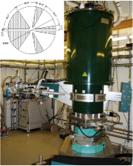
The X-ray windows around the magnet, at the VTI and the 3He insert are from 1 mm thick beryllium each, in order to reduce absorption of the X-ray beam to a minimum. Nevertheless, below 6 keV intensity is reduced already significantly (see Table 3). This limits the usable energy range to energies above 5 keV. The vertical opening of the X-ray windows is ∘ around an aperture of 10 mm. Combining the and angles and the rotation of the sample probe within the cryostat, the horizontal access has no dark angles and large horizontal scattering angles of up to 170∘ can be reached. The horizontal window distribution is shown in the inset of Fig. 8.
| Motor | Range | Accur. | SOC | comment |
|---|---|---|---|---|
| (deg) | (arcsec) | () | ||
| 0.18 | 10 | horizontal | ||
| / | 0.36 | 15 | horizontal | |
| 0.18 | - | vertical | ||
| / | 0.36 | 70 | vertical | |
| 0.36 | 15 | kg | ||
| max. 650 kg load | ||||
| 0 - 360 | 0.18 |
VI Experiment control
All relevant devices at the beamline are controlled by TANGO, including a diffractometer server for moves in reciprocal space. SPECTRA/ONLINE is the data acquisition and beamline control software used at P09 as a command line interface between the user and the Tango devices Kracht (2007); Alfaro et al. (2011). A variety of moves and scans are available.
Some Tango devices special to P09 are mentioned in the following. The multiple motors device allows the definition of slave devices to the energy. For the slave devices, a relation between energy and an angular or linear movement is defined, which then moves the slave device whenever the energy is changed. As slave devices, the undulator, the phase retarder and the polarization analyzer can be selected. Like this, energy scans over a peak with arbitrary polarization (e.g. circular) is feasible. The mirror TANGO device allows selection between the several different mirror configurations and moves the two mirrors into position. The phase retarder TANGO devices are used to select between the different phase plates available on each tower and to move the phase plates to 1/2, 1/4 or 1/8 wave plate condition. The diffractometer device relates the reciprocal space defined by the crystal structure of the sample mounted on the diffractometer to the angular movements of the diffractometer according to the Busing-Levi convention Busing and Levi (1967); You (1999). The HKL library was developed by F. Picca at SOLEIL. It allows selection between different diffractometer geometries and several different modes of diffraction (bisecting, constant-phi, constant-psi, z-axis) Picca (2011).
VII Conclusion and outlook
Beamline P09 has been operational since mid 2010 for external users. Diffraction experiments in both experimental hutches have been performed and show that the equipment is performing according to specification. The investigation of weak non-resonant magnetic reflections in SmFeAsO shows that very weak signals can be measured reliably Nandi et al. (2011). Full polarization analysis, performed at the Ho L3-edge of HoFe3(BO3)4 could be used to show the spiral magnetic order along the c-axis Shukla et al. (2012). From azimuthal scans at the Ir L3-edge of Sr2IrO4, the ordering of the Ir moments in the basal plane could be determined and be related to the ordering in Ba2IrO4 Boseggia et al. (2013). Application of electric fields and reciprocal space mapping was used for the investigation of the electric field induced superlattice reflections from the polar layer at the LaAlO3/SrTiO3 interface Rössle et al. (2013).
Above mentioned representative experiments indicate that P09 combines all the possibilities required for scattering experiments and can be used to perform state of the art experiments in this field. Concerning photon flux, polarization control, polarization analysis, focusing capabilities and high magnetic fields it compares favorably with other experimental stations at -generation synchrotron sources like APS (4ID-D, 6-ID-B) and Spring-8 (BL22XU) as well as Diamond (I16), ESRF (XMAS) and BESSY (MagS).
The type IIa diamond phase-plates, together with the installation of the eToF polarization monitor in the near future will provide means to vary and control polarization in a wide energy range and observe any irregularities during polarization scans, respectively.
Acknowledgements.
The authors would like to acknowledge the staff of the experiment control group FS-EC, M. Hesse and the beamline technology group FS-BT, M. Tischer and the undulator group FS-US and J. Spengler and the general infrastructure group FS-TI. We also want to acknowledge discussion and advice during the planning of the beamline from O.H. Seeck, J.C. Lang, C. Detlefs, P. Thompson and L. Bouchenoire. Also, we would like to thank K. Pflaum, D. Samberg, A. Gade and R. Döring for engineering and technical support.References
- Vettier (2012) C. Vettier, Eur. Phys. J. Special Topics 208, 3 (2012).
- Beale et al. (2012) T. Beale, G. Beutier, S. Bland, A. Bombardi, L. Bouchenoire, O. Bunau, S. D. Matteo, J. Fernandez-Rodriguez, J. Hamann-Borrero, J. Herrero-Martin, et al., Eur. Phys. J. Special Topics 208, 89 (2012).
- Dmitrienko (1983) V. E. Dmitrienko, Acta Cryst. A 39, 29 (1983).
- Gibbs et al. (1988) D. Gibbs, D. Harshman, E. Isaacs, D. McWhan, D. Mills, and C. Vettier, Phys. Rev. Lett. 61, 1241 (1988).
- Murakami et al. (1998) Y. Murakami, H. Kawada, H. Kawata, M. Tanaka, T. Arima, Y. Moritomo, and Y. Tokura, Phys. Rev. Letters 80, 1932 (1998).
- Blume (1985) M. Blume, J. Appl. Phys. 57, 3615 (1985).
- Di Matteo (2012) S. Di Matteo, J. Phys. D: Appl. Phys. 45, 163001 (2012).
- Balewski et al. (2004) K. Balewski, W. Brefeld, W. Decking, H. Franz, R. Röhlsberger, and E. Weckert, Tech. Rep., Deutsches Elektronen-Synchrotron DESY, Hamburg, Germany. (2004).
- Seeck (2008) O. Seeck, Xtrace: Ray tracing program for x-rays (2008).
- Seeck et al. (2012) O. H. Seeck, C. Deiter, K. Pflaum, F. Bertam, A. Beerlink, H. Franz, J. Horbach, H. Schulte-Schrepping, B. M. Murphy, M. Greve, et al., J. Synchrotron Radiation 18, 30 (2012).
- Barthelmess et al. (2008) M. Barthelmess, U. Englisch, J. Pflüger, A. Schöps, J. Skupin, and M. Tischer, Proceedings of EPAC08 p. 2320 (2008).
- Lengeler et al. (1999) B. Lengeler, C. Schroer, J. Tummler, B. Benner, M. Richwin, A. Snigirev, I. Snigireva, and M. Drakopoulos, J. Synchrotron Rad. 6, 1153 (1999).
- Blume and Gibbs (1988) M. Blume and D. Gibbs, Phys. Rev. B 37, 1779 (1988).
- Detlefs et al. (2012) C. Detlefs, M. S. del Rio, and C. Mazzoli, Europ. Phys. J. Special Topics 208, 359 (2012).
- Paolasini et al. (2007) L. Paolasini, C. Detlefs, C. Mazzoli, S. Wilkins, P. P. Deen, A. Bombardi, N. Kernavanois, F. de Bergevin, F. Yakhou, J. P. Valade, et al., J. Synchrotron Rad. 14, 301 (2007).
- Mazzoli et al. (2007) C. Mazzoli, S. B. Wilkins, S. D. Matteo, B. Detlefs, C. Detlefs, V. Scagnoli, L. Paolasini, and P. Ghigna, Phys. Rev. B 76, 195118 (2007).
- Johnson et al. (2008) R. D. Johnson, S. R. Bland, C. Mazzoli, T. A. W. Beale, C.-H. Du, C. Detlefs, S. B. Wilkins, and P. D. Hatton, Phys. Rev. B 78, 104407 (2008).
- Fabrizi et al. (2009) F. Fabrizi, H. C. Walker, L. Paolasini, F. de Bergevin, A. T. Boothroyd, D. Prabhakaran, and D. F. McMorrow, Phys. Rev. Letters 102, 237205 (2009).
- Giles et al. (1994) C. Giles, C. Malgrange, J. Goulon, F. de Bergevin, C. Vettier, A. Fontaine, E. Dartyge, and S. Pizzini, Nuclear Instruments and Methods in Physics Research Section A 349, 622 (1994).
- Scagnoli et al. (2009) V. Scagnoli, C. Mazzoli, P. Bernard, A. Fondacaro, L. Paolasini, C. Detlefs, F. Fabrizi, and F. de Bergevin, J. of Synchrotron Rad. 16, 778 (2009).
- Francoual et al. (2013) S. Francoual, J. Strempfer, D. Reuther, D. Shukla, and A. Skaugen, Journal of Physics: Conference Series 425, 132010 (2013).
- Okitsu et al. (2001) K. Okitsu, Y. Ueji, K. Sato, and Y. Amemiya, J. Synchrotron Rad. 8, 33 (2001).
- Inami et al. (2013) T. Inami, S. Michimura, and T. Matsumura, Journal of Physics: Conference Series 425, 132011 (2013).
- Härtwig and Connell (2005) J. Härtwig and S. Connell, Synchrotron Radiation News 18, 15 (2005).
- Sumiya et al. (1997) H. Sumiya, N. Toda, Y. Nishibayashi, and S. Satoh, Journal of Crystal Growth 178, 485 (1997).
- Goulon et al. (1996) J. Goulon, C. Malgrange, C. Giles, C. Neumann, A. Rogalev, E. Moguiline, F. D. Bergevin, and C. Vettier, J. Synchrotron Radiation 3, 272 (1996).
- Bouchenoire et al. (2012) L. Bouchenoire, R. J. H. Morris, and T. P. A. Hase, Appl. Phys. Lett. 101, 064107 (2012).
- Dommach et al. (2007) M. Dommach, H. Franz, and D. Samberg, HASYLAB Annual Report pp. 169–170 (2007).
- Ilchen et al. (2009) M. Ilchen, S. Deinert, L. Glaser, F. Scholz, J. Seltmann, B. Terka, P. Walter, J. Viefhaus, S. Francoual, D. Reuther, et al., HASYLAB Annual Report (2009).
- You (1999) H. You, J. Appl. Cryst. 32, 614 (1999).
- Kracht (2007) T. Kracht, ONLINE (2007), URL http://hasyweb.desy.de/services/computing/online/online.html.
- Alfaro et al. (2011) M. Alfaro, M. Flemming, J. Grabitz, T. Kracht, B. Lewendel, T. Nunez, P. van der Reest, A. Rothkirch, F. Schlünzen, and E. Wintersberger, Proceedings of ICALEPCS (2011).
- Busing and Levi (1967) W. R. Busing and H. A. Levi, Acta Cryst. 22, 457 (1967).
- Picca (2011) F.-E. Picca, HKL (2011), URL http://people.debian.org/~picca/hkl/index.html.
- Nandi et al. (2011) S. Nandi, Y. Su, Y. Xiao, S. Price, X. F. Wang, X. H. Chen, J. Herrero-Martin, C. Mazzoli, H. C. Walker, L. Paolasini, et al., Phys. Rev. B 84, 054419 (2011).
- Shukla et al. (2012) D. Shukla, S. Francoual, A. Skaugen, M. v. Zimmermann, H. Walker, L. Bezmaternykh, I. A. Gudim, V. L. Temerov, and J. Strempfer, Phys. Rev. B 86, 224421 (2012).
- Boseggia et al. (2013) S. Boseggia, R. Springell, H. Walker, H. Rønnow, C. Rüegg, H. Okabe, M. Osobe, R. Perry, S. Collins, and D. McMorrow, Phys. Rev. Lett. 110, 117207 (2013).
- Rössle et al. (2013) M. Rössle, K. Kim, A. Dubroka, P. Marsik, C. Wang, R. Jany, C. Richter, J. Mannhart, C. Schneider, A. Frano, et al., Phys. Rev. Letters 110, 136805 (2013).