Future liquid Argon detectors
Abstract
The Liquid Argon Time Projection Chamber offers an innovative technology for a new class of massive detectors for rare-event detection. It is a precise tracking device that allows three-dimensional spatial reconstruction with mm-scale precision of the morphology of ionizing tracks with the imaging quality of a “bubble chamber”, provides information with high sampling rate, and acts as high-resolution calorimeter for contained events. First proposed in 1977 and after a long maturing process, its holds today the potentialities of opening new physics opportunities by providing excellent tracking and calorimetry performance at the relevant multi-kton mass scales, outperforming other techniques. In this paper, we review future liquid argon detectors presently being discussed by the neutrino physics community.
keywords:
Neutrino detectors , Liquid Argon detectors , Liquid Argon Time Projection Chambers1 Introduction
The Liquid Argon Time Projection Chamber (LAr TPC) [1] is the successful marriage between the “gaseous” TPC chamber and “the liquid argon calorimeter”, to obtain a combined dense and very fine-grained three-dimensional tracking device with local information and a homogenous full sampling calorimeter.
On one hand, the “gaseous” TPC [2] has been a seminal development in particle tracking detectors. Unlike any other tracking detector, it provided superb capabilities for tracking of charged particles coupled with electric charge (when embedded in a B-field), momentum and type identification through energy-loss measurements. It was the only tracking detector where for each point on the track, x-, y- and z-coordinates were measured simultaneously and with very high spatial resolution. This played a particularly important role in pattern recognition of complex reactions.
On the other hand, the invention of the homogeneous liquid argon ionization chamber has allowed the energy measurement by total absorption with an unprecedented precision. As was pointed out in the pioneering work [3], liquid argon is a medium that satisfies calorimetry requirements better than many other materials. All the energy is ideally converted into ionisation through the development of the cascade showers (electromagnetic and hadronic). The charge is drifted across a gap and picked up electronically with sensitive charge preamplifiers. The integrated collected charge yields, once calibrated, the incoming particle energy. Although argon is a non-compensating medium, the imaging properties of the LAr TPC would in principle allow to pass events through sophisticated energy-flow algorithms and perform “offline” compensation for best performance achievements.
As a result, the combined and excellent tracking-calorimeter performances of the LAr TPC and a design that can be extrapolated to giant multi-kton scale [4, 5], allow to contemplate next-generation massive neutrino detectors with higher signal efficiency and effective background discrimination compared to other techniques, with optimal conditions to detect, identify and precisely measure a very large class of neutrino interactions from the lowest energies in the MeV range to complex multi-GeV events.
Compared to the current state-of-the art represented by SuperKamiokande, multi-kton liquid argon detectors will open new so-far-unexplored physics domains thanks to the improved performance, and they hence represent a complementary approach to gigantic Water-Cerenkov detectors like HyperKamiokande [6, 7].
2 Physical parameters and challenges
Some relevant physical properties of argon are summarised in Table 1.
| Atomic number | 18 |
|---|---|
| Molecular weight | 39.948 gmol |
| Natural concentration | 0.934% of air |
| Melting point | 83.4K at 1 atm |
| Boiling point | 87.3K at 1 atm |
| Triple point | 83.8K at 0.687 bar |
| Liquid density (at 83.7K) | 1392.8 kgm3 |
| Latent heat (1 atm) | 160.81 kJkg |
| Dielectric constant | 1.5 |
| Electric breakdown | 1.1–1.4 MVcm |
| for m.i.p. | 2.12 MeVcm |
| Ionisation energy () | 23.6 eV |
| Excitation energy () | 19.5 eV |
| Radiation length | 14 cm |
| pair production length | 18 cm |
| Molière radius | 9.28 cm |
| Nuclear interaction length | 84 cm |
| Critical energy | 30 MeV |
Liquid Argon (87 K, 1 bar) is a high density, rather cheap and easily accessible by-product of the air liquefaction process. The concept of the LAr TPC is illustrated in Figure 1.
Quasi-free electrons from ionising tracks are easily drifted in LAr with a drift velocity mm/s with a modest electric field of kVcm. In comparison, the drift velocity of ions is totally negligible. The electron cloud diffusion is rather small, as the spatial spread of the cloud given by (with are the longitudinal and transversal diffusion coefficients 4cm2/s, 13cm2/s), is at the level of mm after several meters of drift path . For an ultimate drift of 20 m at 1 kV/cm, the longitudinal(resp. transversal) diffusion is 3 mm(resp. 5 mm). Beyond this drift distance, the images will be significantly distorted compared to the canonical imaging pitch. In order to create the image of events in the chamber volume, the ionisation electrons are drifted towards readout planes segmented in individual electrodes with a sampling pitch of 3 mm or . The drift motion induces currents that are continuously shaped and digitised by the readout electronics. Signal waveforms are processed offline by reconstruction and pattern recognition algorithms to determine the features of the events.
The LAr scintillation properties are also excellent with about 40000 photons/MeV at 0.5 kV/cm, although the light is primarily localised around 128 nm (DUV) and hence cannot be directly efficiently detected by photomultipliers (PMT) as it is does not traverse glass or even crystal windows. In order to be directly sensitive, PMTs with a window can be employed. A practical solution with glass window PMTs consists in coating surfaces of the detector and of the PMTs with wavelength shifters, such as e.g. TPB [8]. The scintillation light can provide the absolute time of an event (), a prompt trigger, and also pulse shape discrimination.
Several technical challenges have limited the use and widespread of the LAr TPC technology. The recent progresses and achievements are however transforming pioneering R&D efforts into realistic designs for very large detectors. We list some issues relevant to the implementation of the LAr TPC at the largest possible scale:

-
1.
The ionisation charge yield after e-ion recombination for a m.i.p. particle is about 1 fC or 6000 per mm of track. The lack of charge amplification in the liquid requires fC-level charge sensitive preamplifiers and necessitate to minimise the capacitance load from the detector and cables . In order to maintain a signal-to-noise (S/N) ratio for m.i.p. particles, the preamplifiers must typically have a noise ENC for pF.
-
2.
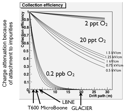
The long drift path requires an ultra-high level of purity in the medium. The expected ionisation charge attenuation due to attachment to impurities as a function of the drift path for various oxygen-equivalent impurity levels and electric fields is shown in Figure 2. The arrows indicate the drift length of the ICARUS T600 [9], MicroBOONE [10], LBNE [11] and LAGUNA-LBNO GLACIER [5, 12]. The free of electro-negative molecules (like , , etc.) must reach a level below 100 ppt level. An impurity level of ppt -equivalent is needed to obtain an electron lifetime greater than 10 ms. Compared to commercially available bulk liquid argon deliveries which typically contain ppm-level purities, the goal is to reduce those impurities by a factor – before filling the main vessel tank. Excellent purity has been reproducibly achieved in various setups always relying on commercially available techniques, of various sizes and capacities, and should not pose a show-stopper for long drift paths.
-
3.
Several independent groups performed numerical simulations and concluded that the vacuum evacuation of the main detector volume could be avoided for larger detectors, thanks to (1) a more favourable surface / volume ratio for larger volume (also larger volumes are less sensitive to micro-leaks), (2) a purification from ppm to 1 ppb is anyhow needed since the initial purity of argon when delivered is typ. ppm (see above), and (3) the outgassing of material is mostly from hot components and impurities frozen at low temperature. GAr flushing and purging were shown to be effective ways to remove air and impurities. Purging on 6 m3 volume has been successfully demonstrated [13]. The piston effect was seen in gas and the impurities reached 3 ppm after several volumes exchange. The Liquid Argon Purity Demonstrator (LAPD) with a size of 30 ton has reach a first milestone, obtaining a better than 3 ms electron lifetime in a large non-evacuated vessel [14].
-
4.
In order to avoid contamination during operation, large ultra high vacuum systems (leak rate mbar lt/s) have been successfully implemented. Microleaks might be the limiting factor to purity and hence long drift paths.
-
5.
Long drift paths and high drift fields imply very high voltages on the cathode. Voltages up to 150 kV have been reached. Immersed voltage multipliers have been successfully developed and operated which could be extrapolated to MV [15, 16], such as to allow 20 m drift distances. However, the long-term stability against discharges of such high voltages remains to be demonstrated.
-
6.
In the single phase configuration, wire chambers with typical wire length m at cryogenic temperature pose mechanical challenges. The breaking of a single wire can be dramatic.
-
7.
The operation at K of large cryogenic systems create technical challenges that can be addressed by storage and process techniques developed by the petrochemical industry [4].
-
8.
A novel method of readout operation called the the double phase LAr LEM TPC with adjustable gain, has been successfully developed and operated [4]. See Section 3. This multiplication produces a significant advantage over traditional systems. These devices are also more robust than the traditional wires with no chance of a channel breaking due to mechanical stress.
3 Double phase readout: the LAr LEM TPC
The Liquid Argon Large Electron Multiplier Time Projection Chamber (LAr LEM-TPC) is a novel kind of double phase (liquid-vapor) noble gas TPC with adjustable gain [4, 5, 16, 17, 18, 19, 20]. Thanks to the gain, each volumetric pixel (voxel) is reconstructed with better signal-to-noise ratio and consequently a lower energy deposition threshold is possible than in single-phase. In addition charge amplification reduces the impact of charge dilution due to the longitudinal diffusion of the electron cloud along the drift paths, and can be used to compensate for potential charge losses due to electronegative impurities diluted in the liquid argon. Therefore, this technology is very promising and possibly represents the “enabling” choice for the realisation of the next generation underground detectors for neutrino physics with imaging technique, in all cases with a significant improvement of the imaging quality compared to the single phase liquid argon TPC [18].
In the LAr LEM TPC, the charge produced by ionizing particles in the liquid is drifted towards the liquid-vapor interface, where electrons are extracted to the vapor phase by means of an appropriate electric field produced by two grids. See Figure 3.
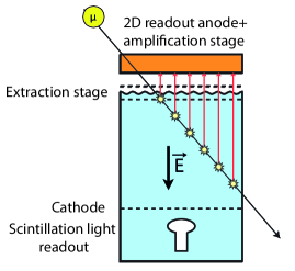
In the vapor phase, Townsend avalanche takes place in the high electric field regions confined in the LEM holes, similar to the situation of the Gas Electron Multiplier (See Ref. in [20]). The LEM is a macroscopic hole electron multiplier built with standard PCB techniques. A HV of typically 3 kV is applied across the two faces creating a strong electric field of 30 kV/cm in the LEM holes leading to multiplication of electrons by avalanches. The amplified charge is collected by a set of segmented electrodes, on which signals are induced. In order to obtain a complete 3D-spatial reconstruction of ionizing events, moving charges have to induce signals on (at least) two complementary X-Y sets of electrode strips. This is achieved thanks to the use of a projective 2D charge X-Y-readout, providing two independent views with 3 mm effective pitch. Based on the GEM 2D readout concept (see Ref. in [20]), it consists of two perpendicular sets of strips with a 50 m thick Kapton spacer in-between. The drifting charge is collected on both sets of strips, based on the principle of balanced charge sharing. The Z (drift) coordinate is derived by measuring the primary electrons drift time.
A high signal-to-noise ratio can be reached in the LAr LEM-TPC thanks to the gas amplification stage. This significantly improves the event reconstruction quality with a lower energy deposition threshold and a better resolution per volumetric pixel (voxel) compared to a conventional single-phase LAr TPC [18]. Figure 4 shows beautiful cosmic ray events collected with a 4080 cm2 double phase LAr LEM-TPC prototype [16].
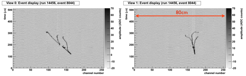
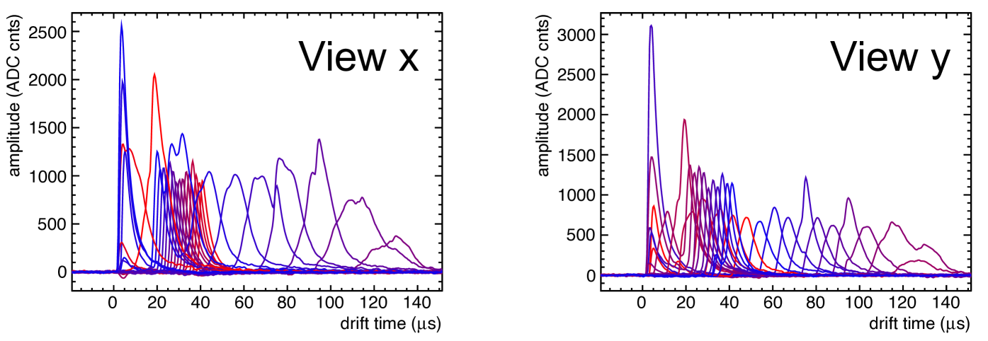
The two pictures correspond to two perpendicular independent views of the event (labelled View 0 and 1). The vertical axes correspond to the drift time and the horizontal axes to the channel number. Signal waveforms from the same prototype are displayed in Figure 5. The excellent S/N is impressive. The charge amplification can compensate for potential losses of signal-to-noise due to the charge diffusion and attachment to electronegative impurities diluted in LAr, which both become more important as the drift length increases. The collection-only readout mode (avoiding the use of induction planes) is also an important asset in the case of complicated topologies, like e.g. in electromagnetic or hadronic showers.
4 Overview of detector performance
The LAr TPC offers excellent combined tracking and calorimetric performance. The detector and physics performance has been studied with small-scale prototypes and detailed detector simulations. The 3-dimensional tracking has a mm-scale spatial resolution with local measurement at each point. It is fully sensitive medium, with a sampling rate for 3 mm pitch, and excellent energy resolution for contained events.
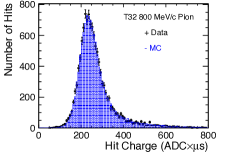
The ability to reproduce well the performance has been demonstrated with a 250 L chamber exposed to a tagged low-momentum kaon test-beam at J-PARC [21]. Figure 6 shows the response measured with the 250 L chamber exposed to the tagged low-momentum kaon test-beam at J-PARC. The data is very well described by the Birks law:
| (1) |
where , kV/cm g/cm2/MeV, the electric field, and the density.
As a consequence of the good understanding of tracking and in particular of the response, we anticipate that particle identification combining range, and imaging information should provide excellent separation with typically efficiency for a rejection factor .
The calorimetric response is less well known. The reconstruction of Michel electrons form stopping muon decay sample was studied in details and yields [22]:
| (2) |
The hadronic calorimetry has never been studied in a test-beam. From Monte-Carlo simulations, the resolution for electromagnetic showers is expected to be:
| (3) |
where the constant term is dominated by the noise and reconstruction effects, while for hadronic showers [23]
| (4) |
where with GEANT3 and with GEANT4. An extensive campaign on a test beam to study calorimetry would represent a great source of information to resolve these discrepancies and improve the calorimetric understanding of the LAr TPC, in particular in view of the precision measurements to be performed in the future at long baseline for oscillation measurements and CP-violation searches.
Similarly, a precise reconstruction of the incoming neutrino energy over a wide range of energies will be an important asset. In a LAr TPC different methods can be used (see [23]). Using the calorimetric approach, one can apply “energy conservation” and sum the deposited energies of all outgoing particles, obtained by summing the measurements along each ionising track to obtain the associated kinetic energies . One should identify final state particles in order to take into account their rest masses. This method is less sensitive to Fermi motion than other methods. Detailed full simulations of CC events between 0 and 10 GeV show an excellent neutrino energy resolution of 8.4% RMS [23].
Kinematical reconstruction of quasi-elastic neutrino interactions has been published with ICARUS 50L data obtained at the CERN WANF [24]. An inclusive cross-section measurement has been obtained with the ArgoNEUT data [25]. Many phenomenological studies were published, for instance on proton decay sensitivities [26], atmospheric neutrino detection (in particular tau appearance) [27, 28], supernovae core collapse neutrinos detection [29, 30], diffuse supernova neutrino background detection [31], indirect dark matter annihilation detection [23], and numerous studies on long baseline neutrino oscillations for CP-violation and mass hierarchy determination [32]. Overall the expected performance of LAr TPCs are compelling in a broad area of energy and in many different physics channels.
5 Overview of new large scale detectors
Table 2 summarises future LAr TPC detectors that are being contemplated. In the following subsections, we briefly overview the basic features of each project.
| Project | LAr mass | Goal | Baseline | Where | Status |
|---|---|---|---|---|---|
| (tons) | (km) | ||||
| Short baseline | |||||
| MicroBOONE | 170 (70 fid.) | low energy excess | 0.47 | FNAL BNB | construction |
| ICARUS-NESSIE | 150+478 | two detectors | 0.5+1.6 | CERN new beam | proposal |
| LAr1 | 2nd detector | 0.7 | FNAL BNB | LoI | |
| Long baseline | |||||
| MODULAr | 5000/unit | shallow depth | 730 | new lab | idea |
| far detector LBL | nearby LNGS | ||||
| GLADE | 5000 | surface | 810 | NUMI off-axis | LoI |
| far detector LBL | |||||
| LBNE | 10000 | surface | 1300 | Homestake+new | CD-1 |
| (35000) | far detector LBL | FNAL beam | |||
| LAGUNA-LBNO | 20000 | underground far | 2300 | Finland+new | EoI |
| (GLACIER) | (up to 70000) | detector LBL+astro | CERN beam | ||
| GLACIER | up to | underground far | 665 | Japan+ | R&D proposal |
| Okinoshima | 100000 | detector LBL+astro | JPARC beam | ||
5.1 MicroBOONE and LAr1 at FNAL
MicroBOONE is a single phase LAr TPC to be located in new Liquid Argon Test Facility (LArTF) at Fermilab in the Booster Neutrino Beam. It has a 70 t fiducial mass, 2.5m drift length, 3 mm wire pitch, and 8256 wires. The physics goal is the study of electrons or photons to help resolve the MiniBOONE “low energy excess”. Notably it will collect a large sample of exclusive final states in the GeV range, and will yield cross-section measurements. From a technology point of view, it will assess the reachable purity in non-evacuable vessels, foam insulation and cold (in liquid) electronics. It should start data taking in 2014.
There is a plan for an additional detector 1kt-scale LAr1 that could be placed in the neutrino beamline to act as a “far” detector for two-detector search at km/GeV. Microboone would act as near detector. The results from MicroBOONE will represent an important benchmark to assess the sensitivity of the combined MicroBOONE+LAr1 setup. The technological aspects would foresee: LBNE design for the wire chamber (see next Section), immersed cold electronics (BNL design), a membrane cryostat, and a cryogenic purity/filtration systems.
5.2 LBNE
LBNE represents a single phase LAr TPC, selected as the technology choice over Water Cerenkov option for next-generation long baseline neutrino physics at Homestake in the US. The primary physics goal is CPV and MH determination with a new conventional neutrino beam from FNAL. The technology challenges are the LNG membrane tank embedded in an underground cavern, large scale non-evacuated vessel, and fully immersed cold electronics. Current plans foresee a staged approach with a “Phase 1” composed of a surface 10 kton detector. Surface operations is a concern that is being addressed. Additional funds could allow to move the detector underground and recover an astrophysics and proton decay programme.
5.3 LAGUNA-LBNO
LAGUNA-LBNO stands for Large Apparatus for Grand Unification and Neutrino Astrophysics & Long Baseline Neutrino. The search for an optimal site in Europe for next generation deep underground neutrino detector has been performed since 2008. An Expression of Interest for a very long baseline neutrino oscillation experiment (LBNO) has been submitted [23]. The main strategy is:
-
1.
A very long-baseline (2000-2300 km) baseline to measure matter effects and determine MH with C.L. within a few years, better and faster than any other proposed experiment.
-
2.
An initial CPV coverage of about 40% at C.L. and a baseline that allows to measure the 2nd maximum.
-
3.
Possibly an incremental mass to 70 kton or second beam with medium long-baseline (1300-1500km) to reduce systematic errors, and to get a CPV coverage of about 70% at C.L.
-
4.
A double phase LAr technology to consider a 20kton detector in the most effective way.
-
5.
A deep underground location for compelling neutrino astrophysics and proton decay searches.
-
6.
A layout that allows the beam infrastructure within “CERN land”, e.g. from the North Area and with a near detector location.
-
7.
A far facility including a magnetised detector.
-
8.
A baseline optimised for the neutrino factory.

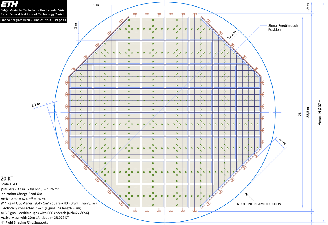
As mentioned above, the LAr detector concept for LAGUNA-LBNO is a simple, scalable detector design and uses the double phase LAr LEM TPC concept. It consists of a single module non-evacuable cryo-tank based on industrial LNG technology. The industrial conceptual design was developed since several years in partnership with specialised industrial partners. Two options for the tank were developed: a 9% Ni-steel and a membrane version (a detailed comparison up to costing of assembly in underground cavern has been performed). The designed were developed in details for three volumes: 20, 50 and 100 kton, but the initial incremental phase of LBNO considers one 20 kton detector (See Figure 7) complemented by a 35 kton magnetised iron detector. LAr filling, purification, and boiloff recondensation has been engineered based on industrial methods for large cryogenic processes. The charge readout (for the 20 kton fiducial volume) has 23 072 kton active mass which can be achieved with a 20 m drift and a 824 active area, composed of 277 056 channels (See Figure 8). The light readout (trigger) comprises 804 8” PMT (e.g. Hamamatsu R5912) WLS coated placed below cathode. A prototype at the kton-scale is being considered at CERN.
5.4 MODULAr
MODULAr [33] is a single phase LAr TPC, realised with a set of two identical but independent units, cloning the design of ICARUS T600. Each unit has 5370 ton mass, 4 m drift length, 6 mm wire pitch, three wire planes, and 50k channels. The physics goals comprise off-axis of the CNGS. For this, a new shallow-depth site approximately 10 km off-axis present LNGS is envisioned.
6 Conclusions
The LAr TPC can offer truly unique and superior imaging performance, in particular for electron appearance and/or in challenging environments like wide-band beams, where excellent energy resolution and good background rejection power are required. When located underground, massive LAr detectors are also capable of delivering compelling atmospheric neutrino detection, very sensitive proton decay searches and astrophysical sources study, in addition to complementary to superb long baseline physics with beams. The worldwide neutrino scientific community should strive for at least one next generation deep-underground 20 kton (SuperKamiokande fid. mass) or more LAr detector.
References
- [1] C. Rubbia, The Liquid Argon Time Projection Chamber: A New Concept for Neutrino Detectors, CERN-EP-INT-77-08.
- [2] J. N. Marx, D. R. Nygren, The time projection chamber, Physics Today 31 (10) (1978) 46–53. doi:10.1063/1.2994775.
- [3] W. Willis, V. Radeka, Liquid Argon Ionization Chambers as Total Absorption Detectors, Nucl.Instrum.Meth. 120 (1974) 221. doi:10.1016/0029-554X(74)90039-1.
- [4] A. Rubbia, Experiments for CP violation: A Giant liquid argon scintillation, Cerenkov and charge imaging experiment?arXiv:hep-ph/0402110.
- [5] A. Rubbia, Underground Neutrino Detectors for Particle and Astroparticle Science: The Giant Liquid Argon Charge Imaging ExpeRiment (GLACIER), J.Phys.Conf.Ser. 171 (2009) 012020. arXiv:0908.1286, doi:10.1088/1742-6596/171/1/012020.
- [6] K. Nakamura, HYPER-KAMIOKANDE: A next generation water Cherenkov detector for a nucleon decay experiment, Front.Phys. 35 (2000) 359–363.
- [7] K. Abe, T. Abe, H. Aihara, Y. Fukuda, Y. Hayato, et al., Letter of Intent: The Hyper-Kamiokande Experiment — Detector Design and Physics Potential —arXiv:1109.3262.
- [8] V. Boccone, et al., Development of wavelength shifter coated reflectors for the ArDM argon dark matter detector, JINST 4 (2009) P06001. arXiv:0904.0246, doi:10.1088/1748-0221/4/06/P06001.
- [9] S. Amerio, et al., Design, construction and tests of the ICARUS T600 detector, Nucl.Instrum.Meth. A527 (2004) 329–410. doi:10.1016/j.nima.2004.02.044.
- [10] H. Chen, et al., Proposal for a New Experiment Using the Booster and NuMI Neutrino Beamlines: MicroBooNE.
- [11] T. Akiri, et al., The 2010 Interim Report of the Long-Baseline Neutrino Experiment Collaboration Physics Working GroupsarXiv:1110.6249.
- [12] A. Rubbia, The LAGUNA design study: Towards giant liquid based underground detectors for neutrino physics and astrophysics and proton decay searches, Acta Phys.Polon. B41 (2010) 1727–1732.
- [13] A. Curioni, L. Epprecht, A. Gendotti, L. Knecht, D. Lussi, et al., Towards a liquid Argon TPC without evacuation: filling of a 6 m3 vessel with argon gas from air to ppm impurities concentration through flushing, J.Phys.Conf.Ser. 308 (2011) 012024. arXiv:1009.4073, doi:10.1088/1742-6596/308/1/012024.
- [14] B. Rebel, Performance and technical challenges of liquid argon detectors, AIP Conf.Proc. 1382 (2011) 106–108. doi:10.1063/1.3644282.
- [15] S. Horikawa, et al., Feasibility of high-voltage systems for a very long drift in liquid argon TPCs, J.Phys.Conf.Ser. 308 (2011) 012027. arXiv:1009.4908, doi:10.1088/1742-6596/308/1/012027.
- [16] A. Badertscher, A. Curioni, U. Degunda, L. Epprecht, A. Gendotti, et al., First operation and drift field performance of a large area double phase LAr Electron Multiplier Time Projection Chamber with an immersed Greinacher high-voltage multiplier, JINST 7 (2012) P08026. arXiv:1204.3530, doi:10.1088/1748-0221/7/08/P08026.
- [17] A. Badertscher, L. Knecht, M. Laffranchi, A. Marchionni, G. Natterer, et al., Construction and operation of a Double Phase LAr Large Electron Multiplier Time Projection ChamberarXiv:0811.3384.
- [18] A. Badertscher, L. Knecht, M. Laffranchi, D. Lussi, A. Marchionni, et al., Operation of a double-phase pure argon Large Electron Multiplier Time Projection Chamber: Comparison of single and double phase operation, Nucl.Instrum.Meth. A617 (2010) 188–192. arXiv:0907.2944, doi:10.1016/j.nima.2009.10.011.
- [19] A. Badertscher, A. Curioni, S. Horikawa, L. Knecht, D. Lussi, et al., Stable operation with gain of a double phase Liquid Argon LEM-TPC with a 1 mm thick segmented LEM, J.Phys.Conf.Ser. 308 (2011) 012016. arXiv:1010.2482, doi:10.1088/1742-6596/308/1/012016.
- [20] A. Badertscher, A. Curioni, L. Knecht, D. Lussi, A. Marchionni, et al., First operation of a double phase LAr Large Electron Multiplier Time Projection Chamber with a two-dimensional projective readout anode, Nucl.Instrum.Meth. A641 (2011) 48–57. arXiv:1012.0483, doi:10.1016/j.nima.2011.02.100.
- [21] O. Araoka, A. Badertscher, A. Curioni, S. DiLuise, U. Degunda, et al., A tagged low-momentum kaon test-beam exposure with a 250L LAr TPC (J-PARC T32), J.Phys.Conf.Ser. 308 (2011) 012008. arXiv:1105.5818, doi:10.1088/1742-6596/308/1/012008.
- [22] S. Amoruso, et al., Measurement of the mu decay spectrum with the ICARUS liquid argon TPC, Eur.Phys.J. C33 (2004) 233–241. arXiv:hep-ex/0311040, doi:10.1140/epjc/s2004-01597-7.
- [23] A. Stahl, et al., Expression of Interest for a very long baseline neutrino oscillation experiment (LBNO) - CERN SPSC 2012-021 / SPSC-EOI-007.
- [24] F. Arneodo, et al., Performance Of A Liquid Argon Time Projection Chamber Exposed To The WANF Neutrino Beam, Phys.Rev. D74 (2006) 112001. arXiv:physics/0609205, doi:10.1103/PhysRevD.74.112001.
- [25] C. Anderson, et al., First Measurements of Inclusive Muon Neutrino Charged Current Differential Cross Sections on Argon, Phys.Rev.Lett. 108 (2012) 161802. arXiv:1111.0103, doi:10.1103/PhysRevLett.108.161802.
- [26] A. Bueno, Z. Dai, Y. Ge, M. Laffranchi, A. Melgarejo, et al., Nucleon decay searches with large liquid argon TPC detectors at shallow depths: Atmospheric neutrinos and cosmogenic backgrounds, JHEP 0704 (2007) 041. arXiv:hep-ph/0701101, doi:10.1088/1126-6708/2007/04/041.
- [27] A. Bueno, A. Martinez de la Ossa, S. Navas, A. Rubbia, Statistical pattern recognition: Application to oscillation searches based on kinematic criteria, JHEP 0411 (2004) 014. arXiv:hep-ph/0407013, doi:10.1088/1126-6708/2004/11/014.
- [28] M. Campanelli, A. Bueno, A. Rubbia, oscillations appearance with kinematic approach at very long baselines (VLBL), Nucl.Instrum.Meth. A451 (2000) 176–181. doi:10.1016/S0168-9002(00)00383-1.
- [29] I. Gil Botella, A. Rubbia, Decoupling supernova and neutrino oscillation physics with LAr TPC detectors, JCAP 0408 (2004) 001. arXiv:hep-ph/0404151, doi:10.1088/1475-7516/2004/08/001.
- [30] I. Gil Botella, A. Rubbia, Oscillation effects on supernova neutrino rates and spectra and detection of the shock breakout in a liquid argon TPC, JCAP 0310 (2003) 009. arXiv:hep-ph/0307244, doi:10.1088/1475-7516/2003/10/009.
- [31] A. Cocco, et al., Supernova relic neutrinos in liquid argon detectors, JCAP 0412 (2004) 002. arXiv:hep-ph/0408031, doi:10.1088/1475-7516/2004/12/002.
- [32] S. K. Agarwalla, T. Li, A. Rubbia, An Incremental approach to unravel the neutrino mass hierarchy and CP violation with a long-baseline Superbeam for large , JHEP 1205 (2012) 154. arXiv:1109.6526, doi:10.1007/JHEP05(2012)154.
- [33] B. Baibussinov, M. Baldo Ceolin, G. Battistoni, P. Benetti, A. Borio, et al., A New, very massive modular Liquid Argon Imaging Chamber to detect low energy off-axis neutrinos from the CNGS beam: Project MODULAr, Astropart.Phys. 29 (2008) 174–187. arXiv:0704.1422, doi:10.1016/j.astropartphys.2008.01.001.