A low cost scheme for high precision dual-wavelength laser metrology
Yitping Kok,1,∗ Michael J. Ireland,2,3, J. Gordon Robertson1, Peter G. Tuthill1, Benjamin A. Warrington2 and William J. Tango1
1Sydney Institute for Astronomy, School of Physics,
University of
Sydney, NSW 2006, Australia
2Department of Physics and Astronomy,
Macquarie University, NSW
2109, Australia
3Australian Astronomical Observatory,
PO Box 915, North Ryde, NSW
1670, Australia
∗Corresponding author: y.kok@physics.usyd.edu.au
Abstract
A novel method capable of delivering relative optical path length metrology with nanometer precision is demonstrated. Unlike conventional dual-wavelength metrology which employs heterodyne detection, the method developed in this work utilizes direct detection of interference fringes of two He-Ne lasers as well as a less precise stepper motor open-loop position control system to perform its measurement. Although the method may be applicable to a variety of circumstances, the specific application where this metrology is essential is in an astrometric optical long baseline stellar interferometer dedicated to precise measurement of stellar positions. In our example application of this metrology to a narrow-angle astrometric interferometer, measurement of nanometer precision could be achieved without frequency-stabilized lasers although the use of such lasers would extend the range of optical path length the metrology can accurately measure. Implementation of the method requires very little additional optics or electronics, thus minimizing cost and effort of implementation. Furthermore, the optical path traversed by the metrology lasers is identical with that of the starlight or science beams, even down to using the same photodetectors, thereby minimizing the non-common-path between metrology and science channels.
OCIS codes: 000.0000, 999.9999.
1 Introduction
The specific problem motivating this research was to measure the relative length of optical paths within an astrometric stellar interferometer to a high degree of precision. Precision in the order of several nanometers allows stellar interferometers of about 100m baseline111separation between two telescopes to achieve angular precision of several microarcseconds. One potential science goal that can be pursued with such angular precision is the detection of exoplanets through narrow-angle astrometry [1, 2, 3, 4, 5]. The basic principle of searching for exoplanets through narrow angle astrometry is to measure the position of a target star with respect to the position of a reference star on the celestial sphere to an angular precision of tens of microarcseconds. Through an optical long baseline stellar interferometer, light from a resolved pair of stars forms interference fringes at different optical delays and the difference in optical delay is proportional to the projected separation of the two stars on the celestial sphere. For these reasons, the relative position of one star with respect to the other can be determined by measuring the difference in optical path where the stellar fringes are found.
High precision measurement of an optical path length can be conducted by analyzing the interference fringes formed by light (e.g. from a laser) traversing the optical path being measured. The maximum optical length measurable by interferometry is limited to the coherence length of the light source because interference fringes are not visible beyond this length. Therefore, lasers, which typically have a long coherence length, are usually the preferred light source. However due to this same reason and the periodicity of the interference fringes, measurement of an optical path length can be ambiguous. The fringe patterns formed by two optical path lengths that differ by exactly one laser wavelength are exactly the same. The measurement is unambiguous only if the optical path length to be measured is within one laser wavelength. This limited range of distance where the metrology can measure accurately is also known as the non-ambiguity range (NAR). A straightforward solution to measure distances larger than the NAR of a single wavelength metrology is to have the optical path length be incremented from zero to the desired length in steps no larger than the NAR and incremental measurement is carried out at each step. But due to practical requirements this solution is not always desirable. Conventionally, instead of one wavelength, two laser wavelengths are used to obtain a long synthetic optical wavelength by means of heterodyne interferometry [6, 7]. However, instead of using the heterodyne detection technique which requires specialized optical elements and hence has higher cost, the dual-wavelength metrology described here and implemented at the Sydney University Stellar Interferometer (SUSI) [8] employs a simple homodyne fringe counting detection scheme together with a (relatively) less precise stepper motor open-loop position control system to extend the range of distance the metrology can accurately measure. The implementation and performance of this metrology, which was found to be easily suitable for our demanding narrow-angle astrometric application with an optical long baseline stellar interferometer, are described hereafter.
2 Optical setup
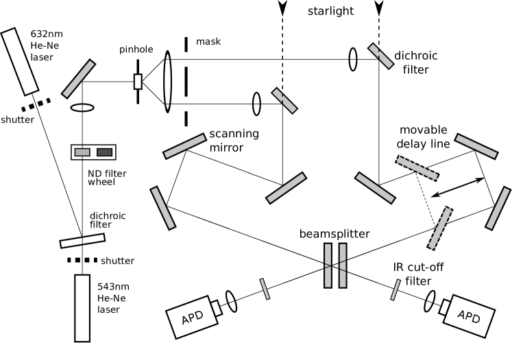
The diagram in Fig. 1 shows a simplified version of the narrow-angle astrometric beam combiner (MUSCA) in SUSI. Instead of depicting the entire SUSI facility for which schematic diagrams can be obtained from [9], the diagram shows only the optical path relevant to the metrology and the beam combiner which is a pupil-plane Michelson interferometer. The light sources for the metrology are two He-Ne lasers; one emits at peak wavelength of m and the other at peak wavelength of m [10, 11, converted from wavelengths in standard (760 torr, 15∘C) dry air]. The quoted values are wavelengths in vacuum but the two lasers are operated in air. Both laser beams are first spatially filtered by pinholes, then collimated and finally refocused into the interferometer. Each refocused beam forms an image at a field lens in front of an avalanche photodiode (APD). The optical path along the left arm of the interferometer (as seen in Fig. 1) is periodically modulated by a piezo-electrically actuated mirror (scanning mirror) to produce temporal fringes, which are then recorded by the pair of APDs as a time series of photon counts. The scanning mirror modulates the optical path in 256 discrete steps in about 70ms per scan period per scan direction. On the right arm of the interferometer, the length of the optical path can be changed by a movable delay line. It is made up of mirrors sitting on a linear translation stage (Zaber222http://www.zaber.com T-LS28M) which is stepper motor driven and has an open loop position control system. The built-in stepper motor converts rotary motion to linear motion via a leadscrew. The leadscrew based open loop position control system has a nominal accuracy of 15m.
It is important to note that, apart from the lasers and their injection optics, all components in Fig. 1 were pre-existing and required for the science goal of the beam combiner. During astronomical observations, the same pair of APDs are used to record both the stellar and the metrology fringes. The optical path of the metrology lasers is designed to trace the optical path of the starlight beams in the beam combiner, which propagates into the instrument from the top as seen in Fig. 1 through a pair of dichroic filters. In this way, the optical path probed by the metrology is nearly identical to the optical path of the starlight and the small difference in optical delay (due to the difference in wavelengths) is invariant under the controlled atmospheric condition [12] in the laboratory in which the optics are housed.
3 Dual-wavelength metrology
Our dual-wavelength metrology is designed to measure the change in optical path length of air brought about by a displacement of the delay line when it is moved from one position to another. The underlying principle of the metrology is to first measure phases of interference fringes of two lasers, operating at wavelengths whose ratio is theoretically not a rational number (but practically a ratio of two large integers due to finite accuracy of the wavelengths), at two different delay line positions and then determine the number of fringe cycles that have evolved as a result of the displacement. The phase measurement is key in this classical two-wavelength approach to displacement metrology. The novel aspect of the metrology described here is the use of optical path modulation to measure the phases of the fringes of the two lasers simultaneously. In an idealized case where the laser wavelengths are perfectly stable and the measurements of the phases are noiseless, one measurement at each delay line position would be enough to uniquely resolve the length of the optical path between the two positions. However, in the real world, due to uncertainties in the phase measurements and laser wavelengths, there are a series of plausible solutions for the optical path length. The span between these plausible solutions is the non-ambiguity range (NAR) of the metrology and is elaborated in Section 4. In order to extend the range of distance the metrology can measure an open loop stepper motor position control system is exploited to narrow down the plausible solutions to a single best fit, thereby yielding the displaced optical path length measurement at interferometric precision. The basic requirement for this two-prong approach is that the NAR arising from fringe phase measurement must be larger than the uncertainty of the stepper motor positioning system. Since the stepper motor positioning system can determine the position of the delay line unambiguously over a large distance range (in the case of T-LS28M, 28mm), the delay line can be moved quickly (2mm/s) from one position to another and fringe phase measurement does not have to be done on the fly but before and after a move.
In order to explain the method in more detail, first, let the distance between a position of the delay line and an arbitrary reference position be expressed in terms of two laser wavenumbers ( and ) as follows,
| (1) |
and are the refractive indices of air at the respective wavenumbers while and or and are the number of full (integer) and fractional wavelengths that fit within this distance. The subscript represents one position of the delay line and if two different positions are considered, then, from Eq. (1),
| (2) |
where represents the difference in optical path length of air between the two delay line positions while , , and . The phases of the laser fringes, and , and their difference, , can be obtained from the photon counts recorded by the APDs. and , on the other hand, cannot be directly determined but can be inferred from the following equality,
| (3) |
where and . Therefore the main observables for the metrology at each delay line position are , , and .
The values of and are determined through a model-fitting method based on Eq. (3). First, a range of guess values are generated based on the optical path length estimated from the stepper motor positioning system, , and the NAR to evaluate the LHS of Eq. (3). Next the result is compared with the RHS of Eq.(3) which is obtained from the phase measurement. Theoretically, there is a unique set of and values that satisfy the equation because is an irrational number. However, due to uncertainty in the phase measurement this is not the case in practice. Instead the set of and that minimizes the error between the RHS and LHS of the equation is the set of values to be used for distance determination in Eq. (2).
4 Non-ambiguity range
As previously described, the metrology measures the length of an optical path by calculating the number of laser wavelengths that can be fitted into it. However, since the ratio of the laser wavenumbers, , can be approximated by a ratio of two integers, e.g. or , the phases of the laser fringes will appear (depending on the uncertainty of the phase measurement) to realign after several wavelengths as suggested by the numerator and denominator of the fraction. This means that the phase differences between the laser fringes will repeat and become indistinguishable from the previous phase realignment if the optical path length is larger than the distance suggested by the wavelength range. Therefore the metrology can only determine the accurate length of the optical path if it is within this range, which is the non-ambiguity range (NAR) of the metrology.
The parameters, and , can take any integer value but in order to determine the value of NAR of the metrology, suppose and . Then the NAR is defined as,
| (4) |
provided that the following inequalities are satisfied for all values of and ,
| (5) |
which is derived from the LHS of Eq. (3) when the phases of the lasers fringes are aligned, hence the RHS is zero. The notation denotes the nearest integer of the real number within the brackets and is the standard error of mean of .
5 Implementation
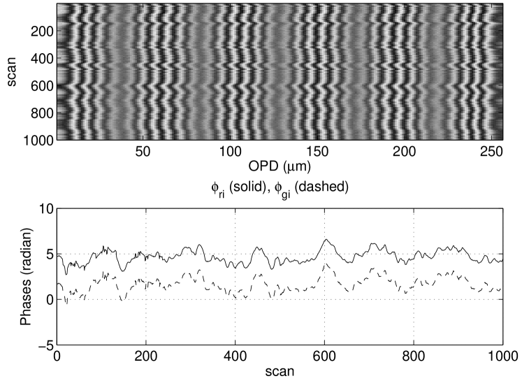
The photon counts recorded from the setup in Fig. 1 are reduced with a program written in MATLAB333http://www.mathworks.com/products/matlab/Octave444http://www.gnu.org/software/octave to determine optical path differences based on the model presented in the previous sections. For each set of laser fringes recorded at one position of the delay line the phases of the fringes (relative to the middle of the scan length), namely , , and , are extracted using a Fast Fourier Transform (FFT) routine. Fig. 2 shows the laser fringes and the phases extracted from them. Because the implementation is numerical and the FFT routine expresses phases in the range of to , a minor tweak to the value of in Eq. (2) may be required to obtained an accurate value of . As a result, the term should be replaced with , where,
| (6) |
The adjustment, , which value is obtained from computer simulation, consists of two parts and is summarized below as,
| (7) |
where and . The value of is given in Table 1 if all the expressions in the first five columns in the table are satisfied, otherwise is zero. For example, according to the first row of Table 1, if , , , and , then . The differences of phases in Eq. (7) and Table 1 are computed by first expressing the phases in the range of 0 to .
The measurement of the phases of the lasers fringes are carried out before and after the delay line is moved for astronomical observation. The displacement of the delay line brings one of the two stellar fringe packets555interference fringes localized in delay space due to limited coherence length of the source into the scan range of the scanning mirror. By measuring the displacement of the delay line and the position of the fringe packets, the optical delay between them, which is the main science observable of MUSCA, can be measured. MUSCA spends about 15–30 minutes, depending on seeing condition of the night sky, integrating on each fringe packet while the metrology takes about 2–3 minutes in total to measure phases of the lasers fringes. The time spent by the metrology includes moving the delay line from one position to another. This sequence of astronomical and metrology measurements is repeated at least 3 times for each science target.
6 Sources of error
The precision of the measurement by the dual-wavelength metrology depends on several factors which will be elaborated individually in this section.
6.A Phase error
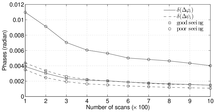
This is the main source of error affecting the precision of the metrology. Errors in measuring and determine the uncertainty in choosing the right value for and and the uncertainty of respectively. The physical processes contributing to this error are photon noise and internal laboratory seeing. At high photon count rates (about 106 counts per second in the SUSI setup), the uncertainty of the phase information obtained from a FFT (or more generally a Discrete Fourier Transform) routine is negligible (i.e. in the order of radians) [13]. Therefore, internal laboratory seeing is the dominant factor. Fig. 3 shows the standard error of the mean of typical measurements of and . The errors decrease with increasing number of scans. If the uncertainty of is less than 0.002 radian (with 500 scans), then the NAR of this metrology is estimated to be 460m ().
6.B Instrumental error
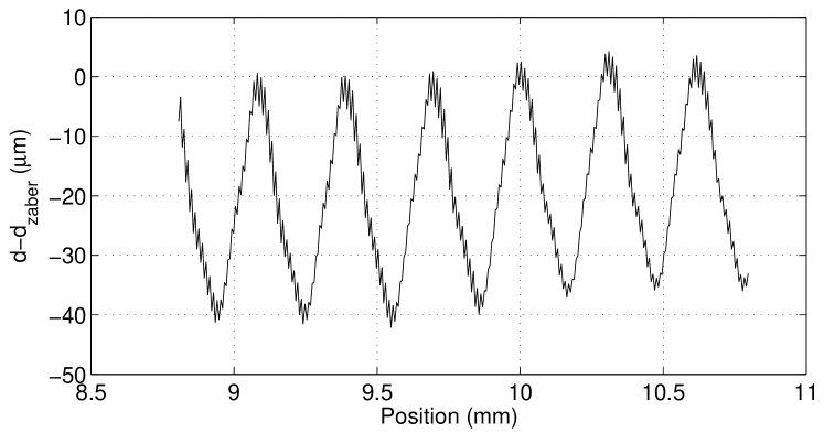
Given an NAR of 460m the difference between an initial guess optical path length, , and its true value must be less than the NAR value. The initial guess value is obtained from the stepper motor positioning system. The characterization of the precision of the system is shown in Fig. 4. The plot in the figure shows the difference between the position of the delay line indicated by the stepper motor positioning system and the position measured by the dual-laser metrology. The cyclical error as seen from the plot is typical for a leadscrew based linear translation stage [14]. Being able to reproduce such a cyclical pattern verifies the accuracy of the dual-laser metrology especially the accuracy of . Instead of the specified 15m accuracy Fig. 4 shows that the leadscrew has a precision of 20m which is still well within the NAR requirement. This requirement is satisfied even though the optical path length change induced by the delay line is twice its actual physical change in position (refer to Fig. 1).
6.C Laser wavelength error
Based on the longitudinal mode spacing specification of the laser (438MHz for the red and 350MHz for the green laser) and the theoretical full width half maximum (FWHM) of the gain profile at the laser wavelengths (1.8GHz for the red and 1.5GHz for the green laser [15]), the relative uncertainty of the wavelength, and , of individual laser is better than . Here the notation means one standard deviation of the wavenumber variation. If , then,
| (8) |
because the refractive indices are similar () and approximately constant [12] between the time when the laser fringes are recorded at the two delay line positions. In the case of SUSI, this condition is true because the fluctuations of ambient temperature in the laboratory are designed to be small within a typical duration of an astronomical observation [8]. Laser wavelength error of this magnitude is not significant when measuring short optical path length but can lead to substantial error in optical path length measurement if the optical path is long. This and the effect of using frequency-stabilized lasers will be discussed in Section 7.
6.D Non-common-path error
Other than being used as light sources for the metrology, the lasers are also used for optical alignment for MUSCA and the rest of the optical setup at SUSI. In the case of MUSCA the alignment between the lasers and starlight beams is critical in order to minimize the non-common-path between the metrology and the science channel. Several other optical elements in the full optical setup at SUSI which also play a role in assisting the alignment process (e.g. retro-reflecting mirrors, lenses, a camera in SUSI’s main beam combiner, etc.) are not included in the simplified version the setup in Fig. 1 but can be referred from [9]. The optics put the pupil and the image of the pinhole and a star on the same respective planes through the aperture of the mask. The lasers and starlight beams should ideally be coaxially aligned in order to minimize the non-common-path between them. However, in the actual optical setup there can be a maximum misalignment of 0.5mm between the pinhole and the image of the star over a distance of about 2m. This translates to a maximum of 0.3 milliradians of misalignment or of relative metrology error. In absolute terms, this error is negligible (1nm) for short (mm) optical path length measurement. However, a more precise alignment is necessary for measurement of longer optical path.
7 Uncertainty of measurement
The uncertainty of the optical path length measurement, , can be derived from Eq. (2). The precision of the stepper motor positioning system (well within the NAR) ensured that the uncertainty of is always zero. The characterization of the delay line in Fig. 4 verified this in practice. Therefore the uncertainty of the optical path length measurement, given below, depends only on the uncertainty of the phase measurements and the laser wavenumbers. In order to simplify the equation, let .
| (9) |
If the phase error, , is more than 1 milliradian, which is typical for this metrology setup then it can be shown that the contribution of the wavenumber error is negligible at short optical path (mm). This value is similar to the separation of two fringe packets of two stars with a projected separation of about 06 in the sky observed with a 160m baseline interferometer. The plot in Fig. 3 shows that a phase error, , of 5 milliradians can be achieved with just 100 scans or more than 500 scans in poor internal (laboratory) seeing conditions. With such magnitude of phase error and according to Eq. (9), the uncertainty of an optical path length measurement is in the order of 5nm or less.
The range of optical path where the contribution of towards the overall error is negligible can be extended if frequency-stabilized lasers are used. Such lasers usually have wavelengths accurate up to m or or smaller in relative error and cost about 3–4 times the price of a regular He-Ne laser666http://www.thorlab.com, http://www.newport.com, http://www.npl.co.uk. At that precision, is not dependent on the optical path length until about 1m which is well beyond the required optical delay for narrow-angle astrometry. However, the extension of the optical path range may also incur other technical cost, which involves improving the precision of optical alignment, increasing the range and speed of the delay line. Therefore, an upgrade to the metrology system described here should take all these factors into consideration.
8 Conclusion
A novel, inexpensive dual-wavelength laser metrology system has been presented and demonstrated to deliver nanometer precision in an experimental implementation. The scheme also boasts the significant advantage of propagating the metrology lasers along an optical path which is identical to the science beam and recording both signals with the same detectors, thereby eliminating non-common-path errors. Due to much pre-existing common hardware, this scheme was particularly straightforward to implement within the context of our specific application (i.e. an optical long baseline astrometric stellar interferometer). However, because it does not require additional specialized optics (e.g. an acoustic-optoelectronic modulator (AOM)) or electronics (e.g. a digital phasemeter) and furthermore has relaxed requirements on the accuracy and stability of the laser wavelengths, it may appeal to similar application within the optics community, especially for stellar interferometry.
Acknowledgments
This research was supported under the Australian Research Council’s Discovery Project funding scheme. Y.K. was supported by the University of Sydney International Scholarship (USydIS).
References
- [1] M. Shao, M. M. Colavita, B. E. Hines, D. H. Staelin, and D. J. Hutter, “The Mark III stellar interferometer,” A&A 193, 357–371 (1988).
- [2] J. T. Armstrong, D. Mozurkewich, L. J. Rickard, D. J. Hutter, J. A. Benson, P. F. Bowers, N. M. Elias, II, C. A. Hummel, K. J. Johnston, D. F. Buscher, J. H. Clark, III, L. Ha, L. Ling, N. M. White, and R. S. Simon, “The Navy Prototype Optical Interferometer,” ApJ 496, 550–571 (1998).
- [3] M. Colavita, J. Wallace, B. Hines, Y. Gursel, F. Malbet, D. Palmer, X. Pan, M. Shao, J. Yu, A. Boden, and Others, “The Palomar testbed interferometer,” ApJ 510, 505–521 (1999).
- [4] N. Schuhler, “Frequency-comb stabilized laser sources for absolute distance metrology at the very large telescope interferometer,” Ph.D. thesis, Universite Louis Pasteur (2006).
- [5] S. Gillessen, M. Lippa, F. Eisenhauer, O. Pfuhl, M. Haug, S. Kellner, T. Ott, E. Wieprecht, E. Sturm, F. Haußmann, C. F. Kister, D. Moch, and M. Thiel, “GRAVITY: metrology,” in “Proc. SPIE ” , vol. 8445 (2012), vol. 8445.
- [6] R. Daendliker, R. Thalmann, and D. Prongue, “Two-wavelength laser interferometry using superheterodyne detection,” Optics Letters 13, 339–341 (1988).
- [7] N. Schuhler, Y. Salvadé, S. Lévêque, R. Dändliker, and R. Holzwarth, “Frequency-comb-referenced two-wavelength source for absolute distance measurement,” Optics Letters 31, 3101–3103 (2006).
- [8] J. Davis, W. J. Tango, A. J. Booth, T. A. ten Brummelaar, R. A. Minard, and S. M. Owens, “The Sydney University Stellar Interferometer - I. The instrument,” MNRAS 303, 773–782 (1999).
- [9] J. G. Robertson, M. J. Ireland, W. J. Tango, P. G. Tuthill, B. A. Warrington, Y. Kok, A. C. Rizzuto, A. Cheetham, and A. P. Jacob, “Science and technology progress at the Sydney University Stellar Interferometer,” in “Proc. SPIE ” , vol. 8445 (2012), vol. 8445.
- [10] R. L. Kurucz, “Linelists,” http://kurucz.harvard.edu/linelists.html (2012).
- [11] B. Edlén, “The refractive index of air,” Metrologia 2, 71 (1966).
- [12] K. E. Erickson, “Investigation of the invariance of atmospheric dispersion with a long-path refractometer,” J. Opt. Soc. Am. 52, 777–780 (1962).
- [13] J. F. Walkup and J. W. Goodman, “Limitations of fringe-parameter estimation at low light levels,” J. Opt. Soc. Am. 63, 399 (1973).
- [14] Zaber, T-Series Positioning Products Technical Notes, Zaber Technologies Inc, 2006th ed. (2006).
- [15] O. Svelto, Principles of Lasers (Plenum Press, 1998), 4th ed.
| F | F | F | F | T | -1 |
| F | F | T | F | F | -1 |
| F | T | F | T | T | -1 |
| F | T | T | T | F | -1 |
| T | F | F | T | F | 1 |
| T | F | T | T | T | 1 |
| T | T | F | F | F | 1 |
| T | T | T | F | T | 1 |
| ; | |||||