Progress of the MICE experiment at RAL
Abstract
The international Muon Ionization Cooling Experiment (MICE) will perform a systematic investigation of ionization cooling of a muon beam. The demonstration comprises one cell of the US Neutrino Factory Study II cooling channel. Results obtained on the construction of the beamline and its instrumentation (STEP I) will be reviewed, together with progress towards final measurements of ionization cooling (STEP IV and VI).
keywords:
Ionization cooling, neutrino beams, neutrino factory, muon colliderThe proposed Neutrino Factory (NF) [1, 2] is a muon storage ring with long straight sections, where decaying muons produce collimated neutrino beams of high intensity and well defined composition, with no uncertainties in the spectrum and flux from hadronic production [3]. The cooling of muons will increase the NF performance and reduce the muon beam emittance up to a factor 2.4 (as described in reference [4] with a cooling section 75 m long) 222By contrast, cooling requirements for a Muon Collider are much more demanding, requiring cooling factors up to . A NF will be the most efficient tool to probe neutrino oscillations and observe CP violation in the lepton sector.
The MICE experiment [5] at RAL aims at a systematic study of a section of the cooling channel of the proposed US NF Study 2 [6], attaining a emittance reduction for a mm rad beam. The 5.5 m long cooling section consists of three liquid hydrogen absorbers, inside focus coil modules (AFC) and eight 201 MHz RF cavities surrounded by lattice solenoids.
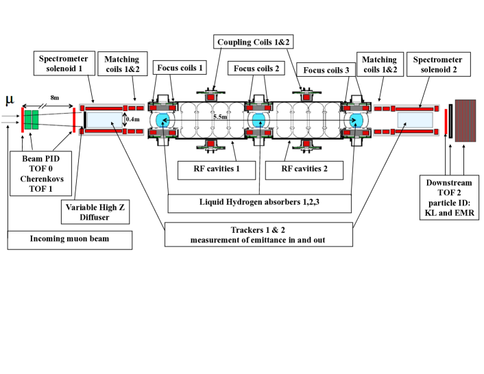
The secondary muon beam from ISIS (140-240 MeV/c central momentum, tunable between mm rad input emittance) enters the MICE cooling section after a diffuser of adjustable thickness. Muons originate from decay inside a 5 m long superconducting (SC) solenoid upstream of the first timing detector (TOF0). As conventional emittance measurement techniques, based on profile monitors, reach barely a precision, a novel method based on single particle measurements has been proposed. For each particle ,,, coordinates are measured before and after the cooling section. In this way, the input and output beam emittances may be determined with a precision up to , that allows a sensible extrapolation of the results to the full cooling channel. The experiment will be done in several steps, of which the first one (STEP I) is the characterization of the beamline [7].
1 MICE STEPI
The driving design criteria for MICE beamline detectors are robustness, in particular of the trackers, to sustain the severe background conditions near the RF cavities and redundancy in particle identification (PID) to keep beam contaminations () well below and reduce systematics on the emittance measurements.
PID is obtained upstream of the first tracking solenoid by two time of flight (TOF) stations (TOF0/TOF1) [8] and two threshold Cerenkov counters (CKOVa/CKOVb) [9], that will provide separation up to 365 MeV/c.
Downstream the PID is obtained instead using an additional TOF station (TOF2) and a calorimeter, made of two detectors (KL and EMR), to separate muons from decay electrons and undecayed pions. While EMR determines precisely the muon momentum by range measurement, KL acts as an active pre-shower to tag electrons. All TOF detectors are used to determine the time coordinate () in the measurement of the emittance.
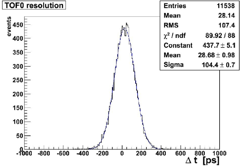
After time-walk corrections and calibration with impinging beam particles [8], the TOF detector timing resolution can be measured by using the time difference between the vertical and horizontal slabs in the same station (see figure 2 for an example). The obtained resolution on the difference translates into time resolution for a full TOF detector with crossed slabs.
The characterization of the MICE beam line has been done mainly using the TOF detectors.
Waiting for the delivery of the tracking solenoids, the beam emittance was preliminary measured, in MICE STEP I, with the TOF detectors only. TOF detectors were used to derive the information for each particle and measure from the time-of-flight between TOF0 and TOF1. Once the initial and final particle coordinates are measured, the muon track through the present MICE channel is estimated as , with transfer matrix and or . The muon momentum is initially estimated via the formula: , with track length and time-of-flight between TOF0 and TOF1. With a separation of m between TOF0 and TOF1, may be measured with a resolution . For the baseline beam, with mm and MeV/c, this corresponds to about , giving a comparable resolution on the transfer matrix . An iterative procedure, based on the transfer matrix, is then used to recompute and . This procedure correct a track length bias ( MeV/c) on reducing it to less than 1 MeV/c.
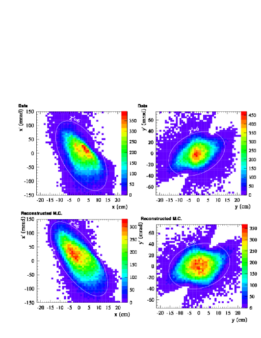
At this point are evaluated from the initial and final muon positions. The horizontal and vertical trace space distributions and are then plotted and the transverse emittances and may be computed, giving an estimation of the normalized emittance via the formula: . Figure 3 shows the trace plots for the MICE baseline beam, with mm and MeV/c, for both experimental data and MC simulation. Even if the agreement is not perfect, the beam occupies the expected regions in trace space. All beams show an RMS beam size of the order of 5-7 cm. This method allows to measure beam emittances at the few per-cent level.
2 Progress towards STEP IV and VI of MICE
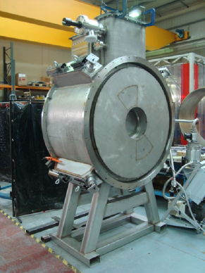
In STEP IV, with the full beam instrumentation system available (including the two trackers [10]) and one Absorber Focus Coil (AFC) in between, it will be possible to measure the input and output beam emittances and evaluate the ionization process with the full design precision. The AFC focus coil, shown in figure 4, provides the guiding magnetic field in the liquid hydrogen () absorber. Just delivered to RAL, the system is under test with the system for full integration inside MICE STEP IV.
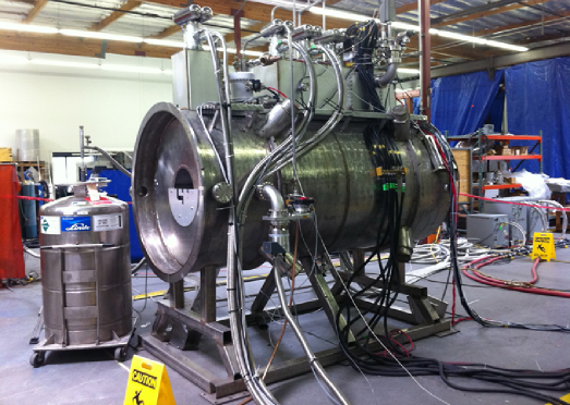
The SC tracking solenoids provide a guiding magnetic field in the fiber tracker. Figure 4 shows the training of the first one at Wang NMR manufacturer. Modifications were implemented to reduce the heat leak to the cold mass, increase the available cooling power via cryocoolers and replace LTS and HTS faulty leads. For STEP VI, two RFCC modules will be installed to compensate for the longitudinal momentum loss and two additional AFC will be installed to increase the ionization effect, responsible of the muon cooling. Each RFCC module consists of four 201 MHz RF cavities and one coupling coil (CC), that will provide the guiding magnetic field inside the cavities. Construction of STEP IV components is almost complete, while STEP VI has 2016 as target date.
References
- [1] D.G. Koshkarev, CERN/ISR-DI/74-62,1974.
- [2] S. Geer, Phys.Rev. D57 (1998) 6989.
- [3] M. Bonesini and A. Guglielmi, Phys.Rept. 433 (2006) 65.
- [4] S. Choubey et al, IDS-NF-20,2011.
- [5] G. Gregoire et al., MICE Proposal to RAL, 2003.
- [6] S.Ozaki et al., BNL-52623, June 2001 ; M.M. Alsharo’a et al., Phys. Rev. ST. Accel. Beams 6 (2003) 081001.
- [7] M.Bogomilov et al., JINST 7 (2012) P05009.
-
[8]
R. Bertoni et al., Nucl. Instr. and Meth. A615 (2010) 14;
M. Bonesini et al. Nucl. Instr. and Meth. A693 (2012) 130. - [9] L. Cremaldi et al., IEEE Trans. Nucl. Sci. 56 (2009) 1475.
- [10] M. Ellis et al., Nucl. Instr. and Meth. A659 (2011) 136