A Federated CloudNet Architecture:
The PIP and the VNP Role
Abstract
We present a generic and flexible architecture to realize CloudNets: virtual networks connecting cloud resources with resource guarantees. Our architecture is federated and supports different (and maybe even competing) economical roles, by providing explicit negotiation and provisioning interfaces. Contract-based interactions and a resource description language that allows for aggregation and abstraction, preserve the different roles’ autonomy without sacrificing flexibility. Moreover, since our CloudNet architecture is plugin based, essentially all cloud operating systems (e.g., OpenStack) or link technologies (e.g., VLANs, OpenFlow, VPLS) can be used within the framework.
This paper describes two roles in more detail: The Physical Infrastructure Providers (PIP) which own the substrate network and resources, and the Virtual Network Providers (VNP) which can act as resource and CloudNet brokers and resellers. Both roles are fully implemented in our wide-area prototype that spans remote sites and resources.
1 Introduction
The virtualization paradigm is arguably the main innovation motor in today’s Internet. Especially node virtualization revolutionized the server business over the last years, and in today’s cloud resources are fully virtualized. However, node virtualization alone is meaningless without access to the cloud resources. Thus, to provide performance guarantees, cloud virtualization needs to be extended to the communication network.
The concept of CloudNets (short for cloud networks) takes the virtualization paradigm one step further, envisioning a unified approach which combines node and link virtualization and offers Quality-of-Service (QoS) guarantees, both on the nodes and the links. Basically, a CloudNet describes a virtual network topology where the virtual nodes represent cloud resources (e.g., storage or computation) which are connected by virtual links.
While CloudNet concepts are already emerging in the context of data centers (e.g., [1, 2]), we expect that in the future, Internet Service Providers (ISP) will also offer flexibly specifiable and on-demand virtual networks, connecting (heterogeneous) cloud resources with connectivity guarantees. Such an elastic wide-area network (WAN) connectivity is attractive in many settings. For example, for inter-site data transfers or state synchronization of a distributed application (such as online gaming). Other use cases are the spill-over (or out-sourcing) to the public cloud in times of resource shortage in the private data center, or the distribution of content to CDN caches.
Note that a CloudNet may not even specify the locations of its constituting resources, and the mapping of the CloudNet can hence be subject to optimization. In fact, the resources of the CloudNets can be migrated over time. For example, latency-critical CloudNets (e.g., realizing a game, an SAP or a social networking service) can be dynamically migrated closer to the users, while delay-tolerant CloudNets (e.g., for large-scale computations or bulk data storage) are run on the remaining servers. Moreover, resources allocated to a CloudNet can be scaled up or down depending on the demand at the different sites. Finally, the decoupling of the CloudNet from the underlying physical infrastructure can also improve reliability, as networks can seamlessly switch to alternative cloud and link resources after a failure, or for maintenance purposes (see e.g., the Amazon outage in April 2011).
This paper presents the anatomy and prototype implementation of a flexible and federated CloudNet architecture. In particular, we will describe the Physical Infrastructure Provider (PIP) role and the Virtual Network Provider (VNP) role. The two roles communicate requirements and allocations via clear negotiation interfaces and using a generic resource description language. Since interfaces between players are generic and since we do not distinguish between physical and virtual resources, a recursive role concept is supported (e.g., a VNP sub-structured into other VNPs).
Moreover, a high generality is achieved by a plugin architecture which allows for replacement of underlying technologies and operating systems.
2 Background
Our architecture is based on the following visions and concepts.
2.1 The Road to CloudNets
Inter-ISP QoS connectivity has already been discussed for many years and is still not widely supported, so why should wide-area and multi-provider CloudNets become a reality now? We believe that the answer lies in the economical incentives, and the recent virtualization and Software-Defined Networking (SDN) trends (e.g., [3]). Content and service providers (e.g., Netflix, Amazon, etc.) as well as content distribution network providers (e.g., Akamai) have become powerful players in the Internet and have stringent resource requirements. CloudNets can be one way for an ISP to monetarize its infrastructure by offering flexible service deployments. For example, in the architecture described in this paper, physical infrastructure providers play a central role in the CloudNet contract hierarchy and participate in the service negotiation, which allows them to become a service partner at eye-level (rather than being a pure bitpipe provider).
We expect that CloudNets will first be deployed inside a single ISP. Such an innovative ISP may benefit from a more efficient resource management,111Google is an example of a recent unilateral initiative in the context of SDN. and may have a first-mover advantage by offering new flexible and elastic services. In the context of an ISP, especially the possibility to deploy (and migrate) services closer to the eyeballs of the users may increase the productivity and revenues: it is known that a better web performance directly translates into higher productivity at Google, and higher revenue at Microsoft Bing or Amazon.
Over time, it can make sense for so far independent CloudNet providers to collaborate. For example, two providers with a local footprint can offer more global CloudNets, or providers can flexibly lease resources to each other to compensate for time-of-day dependent resource shortages.
2.2 Economical Roles
The advent of CloudNets may create a tussle among service and infrastructure providers over who should operate and who should manage the corresponding networks. In [4], we identified two additional roles (i.e., potential market players) besides Physical Infrastructure Providers (PIPs) and Service Providers (SPs): Virtual Network Providers (VNPs) (essentially “resource brokers”) for assembling virtual resources from one or multiple PIPs into a virtual network, and Virtual Network Operators (VNOs) for the installation and operation of the CloudNet provided by the VNP according to the needs of the SP. Our CloudNet architecture defines standardized interfaces between the players to automate the setup of virtual networks (by using a common control plane). In this paper, we will focus on the PIP and VNP roles: both roles have already been fully implemented in our prototype.
2.3 Specification and Specificity
A powerful Resource and CloudNet Description Language (RDL) [5] (a.k.a. FleRD) is used in our architecture. It revolves around basic NetworkElement (NE) objects (for both nodes and links!) that are interconnected via NetworkInterfaces (NI) objects. Keeping these objects generic has the side effect that descriptions of resource aggregations, or non-standard entities (e.g., clusters of providers) is trivially supported: they may be modeled as NEs of an appropriate type and included as topological elements. Thus, we can for example also describe mappings in the context of a reseller. Concretely, NE properties are represented as a set of attribute-value pair objects labeled as Resource and Features. The meaning of resources here is canonic and resources may be shared amongst NEs. Features represent any type of property that is not a resource (e.g., CPU architecture).
One challenge in the communication of specifications and RDL elements across different roles is to ensure consistency, especially for non-topological requirements. For instance, imagine a service provider specification only requires that two nodes are binary compatible (e.g., both are 32 bit architectures or both are 64bit architectures). How can a VNP in charge of distributing such a CloudNet across multiple PIPs fulfill the specification? A simple solution would be that the VNP chooses one of the different options (e.g., both 64 bit) before forwarding the request to the different PIPs. However, this solution comes with a major disadvantage, namely an unnecessary specificity and hence a loss in flexibility: as the VNP has a limited view on the infrastructure of the PIPs only, the VNP’s choice may lead to inefficient allocations (e.g., the two nodes are mapped unnecessarily far away). Alternatively, the VNP may assign the corresponding NEs unique IDs which can be used by the PIPs to agree on a choice themselves. The required communication to achieve this may go via the VNP again, or occur directly between the PIPs. In the following, we will not discuss these options in more detail.
2.4 Plugins
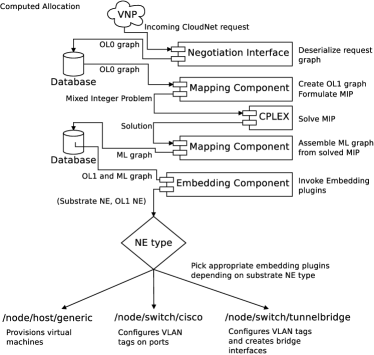
Our architecture is plugin-based to facilitate extensions and adaptations to new networking and virtualization technologies. Plugin-based operation hinges on a feature of the resource description language, namely typed NetworkElements: The NetworkElement objects all have a hierarchical attribute field (this also applies to the NetworkInterface, Resource and Feature objects). This field is a string of hierarchy levels, like a path in a Unix file system (e.g., /node/host/generic).
Much like a CloudNet, any player’s substrate can be described in terms of the RDL. Hence all substrate NEs and all CloudNet NEs will have an attribute field. The higher order hierarchy levels of a CloudNet’s NEs type will be used in the course of the mapping process to determine which substrate NEs they can be allocated to (i.e., both /node/host/mainframe and /node/host/server might be suitable allocations for a /node/host/generic CloudNet NE).
Once a CloudNet’s resources have been mapped to a player’s substrate resources, the lower levels of the substrate NE’s type will be used to determine which plugin to use to provision the CloudNet NEs in question. Depending on the substrate NetworkElement’s hardware or software (e.g., Layer 2 VPNs, Ethernet, OpenFlow, MPLS, mainframes, VM hosts), the appropriate embedding plugin can be chosen to embed all the CloudNet’s resources mapped to the substrate element in question.
3 Testbed & Prototype
The CloudNets prototype is a proof-of-concept implementation of the architecture described above. Currently, the prototype implements the PIP business role (the infrastructure provider) as well as the VNP business role (the resource broker). As a link virtualization plugin we use tagged VLANs: each virtual link is realized as a VLAN. The VLANs provide isolation and enable the demultiplexing of frames to the corresponding virtual machines (to which the connection looks like an Ethernet link).
In the following, we will first give an overview of the testbed and then discuss the prototype. In the context of the prototype, we will refer to virtual nodes as VNodes and to virtual links as VLinks. Moreover, we will sometimes distinguish between the mapping of a CloudNet (i.e., where to allocate the CloudNet in the substrate) and the embedding of a CloudNet (the actual implementation of said allocation).
3.1 Testbed
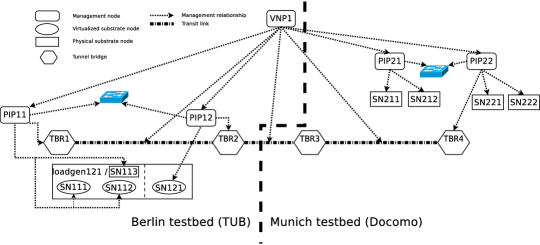
Our network virtualization prototype is run on two separate testbed environments (see Figure 2 for an overview of the available substrate nodes), one at TU Berlin (the Routerlab) and one at NTT DoCoMo Eurolabs, Munich. Both testbeds have a Cisco 4500 series switch carrying both virtual network data plane VLANs and testbed management VLANs. Moreover, both testbeds consist of Sun X4150 machines hosting both substrate resources and the virtual machines running the various roles’ management software. Since there are not enough physical nodes available in the Routerlab, some substrate nodes are KVM virtual machines hosted on one physical node. In the testbed in Munich there are more physical machines available, hence every substrate node is a dedicated physical machine, with the provider management nodes being virtual machines hosted on one physical machine. Substrate nodes, management nodes and virtual nodes run Linux (Ubuntu 8.04). Virtual nodes can either be fully virtualized KVM virtual machines where physical substrate nodes are available, or paravirtualized Xen virtual machines.
The substrate resource allocation for the CloudNet embeddings (CPU and memory resources on virtual machine hosts, and network links for connections) is computed with an optimized Mixed Integer Program (MIP), see Section 3.2. Once the resource allocation is determined, the physical infrastructure provider creates virtual machines, establishes the links between them and hands control over to the customer (by providing console access to the virtual nodes for instance).
At the heart of the prototype lie MySQL databases where each provider keeps all information about its substrate topology and embedded virtual networks. The database holds a representation of the substrate topology (the Underlay (UL) graph, and for each embedded virtual network there is an Overlay (OL) graph describing the virtual network topology and a Mapping Layer (ML) graph describing the locations of the virtual network’s components on the substrate hosting them.
3.2 The Embedding Plugin
In order to embed CloudNets on the given substrate topology, we pursue a mathematical programming approach and use a Mixed Integer Program plugin (short MIP). Currently, this is the only implemented embedding plugin in the prototype, but we are working on a fast alternative for a first embedding stage. In order to focus on the technical aspects, we will not describe the used MIP in full detail, but refer the reader to [6].
The mathematical programming approach is attractive as it is very general and allows us to specify many different types of embeddings and embedding constraints. Especially embeddings on arbitrary Internet infrastructures with heterogeneous resources and links requires a high flexibility. Our Mixed Integer Program supports a simple replacement of the optimization function, without the need to redesign the embedding algorithm. (Rather, the state-of-the-art and optimized algorithms and heuristics provided by standard solvers can be used.) For instance, one possible objective function may arise in scenarios where a CloudNet should be embedded in such a manner that the maximal load or congestion is minimized. In other scenarios, the CloudNets should be embedded in a compact manner in order to be able to shut down the other parts of the physical network, e.g., to save energy. Moreover, our MIP plugin also supports the migration of (parts of) a CloudNet: As the CloudNet requests arriving over time may be hard to predict, certain embeddings computed online in the past may become suboptimal, and re-embeddings and migrations are necessary.
By computing the embedding that would result after a migration together with the migration cost, the MIP allows us to determine, e.g., the cost-benefit tradeoff of migration. For example, our algorithm allows to answer questions such as: Can we migrate CloudNets to a more compact form such that 20% of the currently used resources are freed up, and what would be the corresponding migration cost? It is then left to the (potentially automated) administrator to decide whether the changes are worthwhile.
4 PIP and VNP Roles
In the following, we will focus on the PIP (Physical Infrastructure Provider) role and the VNP (Virtual Network Provider) role, and will describe their implementation. The VNO (Virtual Network Operator) and SP (Service Provider) are not implemented in our prototype yet.
4.1 Graph Serialization
To permit interactions between PIP and VNP roles, a first and important task to be solved is graph serialization. Since the management nodes for the VNP and the PIPs in its substrate graph all run on dedicated machines with dedicated databases, graphs representing the CloudNet topologies have to be serialized into a database independent representation to be sent across the network. To this end we developed a YAML representation of the resource description language, along with serialization/deserialization mechanisms to convert the database representation of a graph into a format suitable for transmission and back into a database representation on the other side.
4.2 The PIP
The PIP role supports arbitrary topology specification and topology modification including live migration of running nodes (within a PIP’s substrate). It mainly consists of a Mapping Component that handles the Mixed Integer Program formulation, the result interpretation and Mapping Layer graph generation, and an extensible (plugin based) Embedding Component that embeds a (partial) CloudNet topology on the PIP’s substrate given its overlay and mapping layer graphs. Figure 1 (left) gives an overview of these components.
4.2.1 Substrate
The PIP’s substrate is largely virtualized in our testbed in Berlin: most substrate nodes are KVM virtual machines running on the testbed’s Sun X4150 machines. The X4150s are interconnected by an IEEE 802.1q-capable switch. The virtualized substrate nodes are assigned unique Ethernet addresses and connected via physical Ethernet interfaces. The CloudNet VNodes are then created on aforemenioned KVM machines. Each virtual link is assigned a unique VLAN tag (picked by the PIP from its assigned range of VLAN tags). These VLAN tags are set on all data plane interfaces (or switch ports) of the substrate nodes on the virtual link.
In addition, some of the X4150 machines are configured to serve as substrate nodes themselves, on top of hosting virtualized substrate nodes. They can host fully virtualized KVM VNodes (as opposed to the virtualized substrate nodes which can only host paravirtualized Xen SNodes).
All substrate nodes store their VM images on an NFS share exported by their controlling PIP. PIPs are responsible for creating VM images and hypervisor configurations, while the substrate nodes’ provisioning scripts take care of the rest.
Interconnections between links that do not involve VNodes are realized by creating bridge devices on dedicated Tunnel Bridge (TBR) nodes. Unlike regular substrate nodes, these do not run OpenVSwitch but the regular Linux bridge. They can host virtual switches and terminate OpenVPN tunnels.
In particular these bridge devices are used to establish VLinks spanning across PIP boundaries (transit links): They interconnect the outside segment of these links (within the specifying VNP’s management scope) with the internal segment of these links (within the PIP’s management scope). The mechanism behind this is based on OpenVPN TAP style layer two tunnels: These are VPN tunnels terminating in virtual Ethernet devices on both tunnel bridges involved in the transit link. Said virtual interfaces trunk all VLinks embedded on the transit link in question and are bridged to the tunnel bridges’ data plane interface.
4.2.2 Cloud Operating System
The prototype provides similar services as modern Cloud Operating Systems:
Automated VM Provisioning. The Embedding Component automatically creates VM images for VNodes (typically by making copies of a template VM image suitable for the hosting substrate node’s hypervisor) and hypervisor configuration files. With everything in place these VMs can be started through an XMLRPC interface to the hosting substrate node’s provisioning scripts. This interface offers a range of basic VM provisioning functionalities such as start, stop, and powercycle.
VM Image Caching. Since the I/O performance of the X4150 machines is rather poor and there is plenty of storage space available we developed a caching scheme to speed up CloudNet embedding. There is a daemon, clipd, that maintains a cache of VM images on every PIP’s exported NFS share (on disk). The Embedding component can request VM images from this daemon’s cache, which are then be moved to their final location on the NFS share, thus greatly speeding up the whole embedding process. The clipd cache is replenished by a cron job while the Mapping Layer/Embedding is inactive.
Customer Console Access to VNodes. Since placement of VNodes is rather opaque to a PIP’s customers—and not relevant as long as their requirements are met—there is a mechanism to automatically look up any given VNode’s hosting substrate node, and offer a proxied serial console session on that very VNode to a customer requesting access.
Automated Link Provisioning. Virtual links are provisioned and brought up automatically. In the Mapping Layer graph they are split up into segments, one for each substrate network element they are mapped to (for instance the two substrate nodes on either end and the switch port the substrate nodes’ data plane interfaces are connected to). For each of these components appropriate Embedding Plugin is called. To date there are Embedding Plugins handling OpenVSwitch based hosts, traditional Linux Bridge based hosts and Cisco 4500 series switches (the latter are configured via SNMP).
4.2.3 Negotiation and Provisioning Interface
A PIP controls its substrate nodes and (physical) switch through an XMLRPC configuration interface. The PIP in turn offers two interfaces to the VNP role: The Negotiation Interface and the Provisioning Interface. Both consist of a range of XMLRPC methods.
Negotiation follows a two-stage protocol: The Negotiation Interface allows for sending preliminary embedding requests for either topology creation or modification of previously embedded topologies. Once a VNP is sure it wants to embed a topology permanently (i.e., after receiving the ‘okays’ from all involved PIPs), it will send a confirmation request for the preliminary topology.
The VNodes of an embedded topology can then be started and stopped through the Provisioning Interface.
4.3 The VNP
The VNP’s high-level architecture is similar to the PIP’s, also comprising a Mapping Component and an Embedding Component. The Mapping Component is for the most part identical to the PIP’s. The major differences are in the embedding component: (1) since the VNP’s substrate consists of entire PIPs rather than physical nodes and links, the VNP has its own set of embedding plugins to interact with PIPs’ Negotiation Interfaces; (2) the Embedding Component contains additional code for the creation of partial graphs which can be mapped to a single PIP.
4.3.1 Substrate
The VNP’s substrate consists of PIP nodes interconnected by transit links222In our prototype, these are represented by OpenVPN (see http://openvpn.net/) tap style tunnels between the PIPs’ tunnel bridge nodes.. Hence the VNP is aware of the topology between PIPs (or a subset of said topology) but does not know anything about the PIP’s internal topology.
4.3.2 Negotiation and Provisioning Interface
A library on the VNP level implements the client side functionality of the PIP’s Negotiation and Provisioning Interface. It is used to send partial topology graphs to PIPs and embed them.
5 Life of a CloudNet Request
In order to illustrate the operation of our prototype, we describe the processing stages a CloudNet topology request graph undergoes from initial submission to the VNP to final embedding of all its nodes on one or multiple PIPs. See Figure 1 (right) for a graphical outline of these stages.
5.1 Incoming CloudNet Request
The CloudNet request in the form of an ‘overlay graph’ (henceforth referred to as OL0 graph) is submitted to the VNP (as a serialized topology graph, through an XMLRPC interface similar to the PIP’s Negotiation Interface). Subsequently, the VNP’s mapping process is started.
5.2 Substrate Synchronization
The first step in mapping a CloudNet request is substrate synchronization: The VNP uses the Negotiation Interface to update the available resources on the PIPs constituting its substrate. In order to both protect PIP’s business secrets (namely the details of its substrate topology), and give the VNP a rough approximation of a given PIP’s available resources, we simply sum up all the resources of a given type in the PIP’s substrate (i.e., a PIP with three substrate nodes that have 4GB RAM each will report an aggregate resource of 12GB RAM to the VNP). These aggregate resources will then be assigned to the /node/host/pip NE representing this PIP in the VNP’s substrate graph.
5.3 Solution of VNP-level MIP
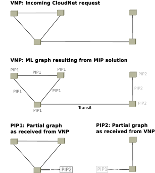
Before proceeding with the mapping process, the VNP completes the OL0 graph, yielding an OL1 graph. This is to account for any vagueness on the upstream entity’s part: e.g., values are chosen for those required resources and features that were left unspecified. For instance the virtualization technology might not have been specified, allowing the VNP to make a choice of its own or pass the the vague graph on to downstream players, who will in turn have the freedom of choice (see the discussion at the end of Section 2.3). Next it formulates the Mixed Integer Program (MIP) for mapping the incoming CloudNet request to its substrate of PIPs. The MIP is based upon the following variables: (1) the incoming OL0 graph’s resource and feature requirements and constraints, (2) the available resources and features on the PIPs constituting the VNP’s substrate (as far as they are known to the VNP), and (3) the available resources and features on the transit links between PIPs.
Once the MIP has been solved the result is translated back into a mapping layer graph, mapping all of the OL1 graph’s Network Elements (NEs) to PIPs and transit links.
5.4 Partial Graph Generation
Now the VNP iterates through the OL1 graph and creates a set of partial graphs, one for each PIP. Each of these partial graphs consists of all the NEs mapped to the PIP in question.
In the course of partial graph generation, stubs for transit links are created. These consist of two special network element types: /node/host/pip and /link/transit.
The /link/transit NE specifies the VLAN to use for this transit link (we opted for letting the VNP pick transit VLANs to avoid implementing an error prone PIP-to-PIP negotiation mechanism for this purpose). This closely matches the most likely real-world scenario, too: A VNP might have an embedding plugin for a transit provider (for instance someone running an MPLS network) with black boxes located at both PIPs’ network edges. This embedding plugin requests a transit link between these two PIPs and receives some kind of link identifier (such as a VLAN tag). The VNP then communicates this link identifier to the PIPs on either end, which allows both PIPs to connect the black box to their local segment of the virtual link.
5.5 Serialization and Transmission
Once the partial graphs have been assembled, each of them is serialized and sent to its hosting PIP through the Negotiation Interface. This currently takes place in a serial manner in our prototype, i.e., partial graphs are sent to PIPs one after the other. If one of the PIPs in the chain turns out to be unable to embed its partial graph the VNP rolls back the already embedded partial graphs (deletes them) and reports a failure status to the upstream entity that sent the original CloudNet request.
5.6 Formulation and Solution
Upon receipt of a partial graph a PIP will—much like the VNP—complete the OL0 graphs to yield OL1 graphs, and formulate the MIP for mapping the incoming partial CloudNet request to its substrate of physical hardware. The program is based on the following variables: (1) the incoming partial graph’s resource and feature requirements and constraints, (2) the available resources and features on this PIP, and (3) the available resources and features on this PIP’s outgoing transit links leading to requested destinations.
Once the MIP has been solved the result is translated back into a mapping layer graph, mapping all of the OL1 graph’s Network Elements to substrate links and nodes. Control passes to the Embedding Component now which will configure the topology’s VLANs on the switch as specified by the Mapping Component and create the VNodes’ images and hypervisor configuration. With everything in place the PIP reports success to the VNP which sent the (partial) CloudNet creation request.
5.7 Bootup and Handoff
Once success has been reported back to the VNP by all PIPs involved in the CloudNet creation request, the VNP confirms all these requests through the PIPs’ Negotiation Interface, uses the PIPs’ Provisioning Interface to start the newly created VNodes (the links will already have been brought up in the course of negotiation). Finally, the VNP hands control over the CloudNet to the requesting upstream entity (typically in the form of console interfaces).
6 Outlook
Our proof-of-concept prototype is optimized for flexibility and generality rather than performance. Although it is already fully functional, several extensions are planned.
Currently, our prototype only supports migrations within a PIP. To enable VNode migration across PIP boundaries, a mechanism is required that orchestrates migration on the VNP side and makes sure space for migrating VNodes is allocated and ready before migration. This implies slight modifications to the negotiation and provisioning interfaces and some changes to the PIP’s embedding component.
Moreover, negotiations with PIPs currently take place in a serial manner. Yet it would be desirable to negotiate with all involved PIPs in parallel, thus exploiting the distributed nature of the architecture. Finally, we will also need to address the problem of terminal attachment and develop a mechanism for attaching clients to CloudNets. We are currently envisioning a role that presents itself as a PIP on the CloudNet side with a special customers resource that contains the number of currently connected terminals. Thus, scenarios such as a Service Provider specifying CloudNet requirements like “My service must reach 20k or more terminals!” or “My service must reach all Swiss users at a latency below 20ms!” are supported.
References
- [1] G. Wang and E. Ng. The impact of virtualization on network performance of Amazon EC2 data center. In Proc. IEEE INFOCOM, 2010.
- [2] C. Wilson, H. Ballani, T. Karagiannis, and A. Rowtron. Better never than late: meeting deadlines in datacenter networks. In Proc. ACM SIGCOMM Conference, pages 50–61, 2011.
- [3] D. Drutskoy, E. Keller, and J. Rexford. Scalable network virtualization in software-defined networks. In Proc. IEEE Internet Computing, 2012.
- [4] G. Schaffrath, C. Werle, P. Papadimitriou, A. Feldmann, R. Bless, A. Greenhalgh, A. Wundsam, M. Kind, O. Maennel, and L. Mathy. Network virtualization architecture: Proposal and initial prototype. In Proc. ACM SIGCOMM VISA, pages 63–72, 2009.
- [5] G. Schaffrath, S. Schmid, I. Vaishnavi, A. Khan, and A. Feldmann. A resource description language with vagueness support for multi-provider cloud networks. In Proceedings of International Conference on Computer Communication Networks (ICCCN), 2012.
- [6] G. Schaffrath, S. Schmid, and A. Feldmann. Optimizing long-lived cloudnets with migrations. In Proc. 5th IEEE/ACM International Conference on Utility and Cloud Computing (UCC), 2012.