A Time Projection Chamber for High-Rate Experiments: Towards an Upgrade of the ALICE TPC
Abstract
A Time Projection Chamber (TPC) is a powerful detector for 3-dimensional tracking and particle identification for ultra-high multiplicity events. It is the central tracking device of many experiments, e.g. the ALICE experiment at CERN. The necessity of a switching electrostatic gate, which prevents ions produced in the amplification region of MWPCs from entering the drift volume, however, restricts its application to trigger rates of the order of .
Charge amplification by Gas Electron Multiplier (GEM) foils instead of proportional wires offers an intrinsic suppression of the ion backflow, although not to the same level as a gating grid. Detailed Monte Carlo simulations have shown that the distortions due to residual space charge from back-drifting ions can be limited to a few , and thus can be corrected using standard calibration techniques. A prototype GEM-TPC has been built with the largest active volume to date for a detector of this type. It has been commissioned with cosmics and particle beams at the FOPI experiment at GSI, and was employed for a physics measurement with pion beams.
For future operation of the ALICE TPC at the CERN LHC beyond 2019, where Pb-Pb collision rates of are expected, it is planned to replace the existing MWPCs by GEM detectors, operated in a continuous, triggerless readout mode, thus allowing an increase in event rate by a factor of 100. As a first step of the R&D program, a prototype of an Inner Readout Chamber was equipped with large-size GEM foils and exposed to beams of protons, pions and electrons from the CERN PS.
In this paper, new results are shown concerning ion backflow, spatial and momentum resolution of the FOPI GEM-TPC, detector calibration, and resolution with both detector prototypes. The perspectives of a GEM-TPC for ALICE with continuous readout will be discussed.
keywords:
Gas Electron Multiplier , GEM , Time Projection Chamber , TPC , Ion Backflow , FOPI , ALICE1 Introduction
A Time Projection Chamber (TPC) [1] is a high-resolution detector providing three-dimensional tracking of charged particles even in very high multiplicity environments such as heavy ion collisions, e.g. at the ALICE experiment at CERN’s LHC [2]. The large number of space points measured along each particle track considerably eases the task of pattern recognition for complex events, and in addition allows the identification of each particle by measuring its specific energy loss. Since track reconstruction requires a precise knowledge of the electric and magnetic fields inside the chamber, distortions have to be kept at a minimum. To this end, TPCs are normally used in a gated mode, where an electrostatic grid blocks the ions created in the amplification stage, usually an array of proportional wires, before they reach the drift volume. This introduces inevitable dead times and limits the maximum trigger rate to a few kHz. After the second long shutdown of the LHC in 2018, a luminosity for Pb-Pb collisions of is expected. In order to make full use of the increase in luminosity, ALICE plans to record all minimum bias events at a rate of about [3], about two orders of magnitude higher than at present. As a result particle tracks from 5 events on average will be superimposed in the drift volume. A continuous, untriggered readout of the TPC is the obvious mode of operation, precluding the use of a gating grid.
2 A GEM-based TPC
The use of Gas Electron Multiplier foils [4] instead of proportional wires offers an intrinsic suppression of the ion backflow [5], although not to the level of as with a gating grid. Suppression factors around or below the percent level have been reached [6], but strongly depend on the gas composition and the magnetic field. Together with low-noise readout electronics, allowing an operation at gas gains of the order of , this results in about ions drifting back into the drift volume per electron arriving at the amplification stage. The drift distortions caused by the ion space charge have been shown in simulations to be of the order of a few , which can be corrected using standard calibration techniques [7, 3], provided the ion charge distribution is stable over time scales of the order of .
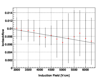
In order to minimize distortions for the case of the ALICE TPC, which operates in a low solenoid field of , measurements of the crucial ion backflow (), defined as the ratio of cathode to anode current, have been performed in triple GEM detectors with Ar- and Ne-based gas mixtures without magnetic field. Figure 1 shows this quantity for an Ar/CO2 (70/30) mixture as a function of the induction field, i.e. the field between the last GEM and the readout anode. Values of the of about have been reached in a configuration with a low drift field, alternatingly high and low electric fields between GEMs, and the highest gain in the last GEM.
It is to be noted that such a configuration is not optimal for stability of the chamber against discharges in case of highly ionizing particles [8]. Moving to a Ne/CO2 (90/10) mixture as currently used in the ALICE TPC requires a higher drift field () and lower fields between GEMs ( in order not to enter a regime of charge amplification). As a consequence, the is higher by about a factor of 5, as can be seen in Fig. 2. Steps to further decrease this value include adding small admixtures of N2 to the gas and a fourth GEM, guided by microscopic simulations of charge transfer processes in GEMs [9].

Strategies to eliminate the problem completely, e.g. by using foils with additional patterning on one side [10] are under investigation, but are currently limited by the size of foils.
3 The FOPI GEM-TPC
In the framework of the PANDA experiment at FAIR a prototype GEM-TPC has been built which is the largest detector of this kind to date [11, 12].
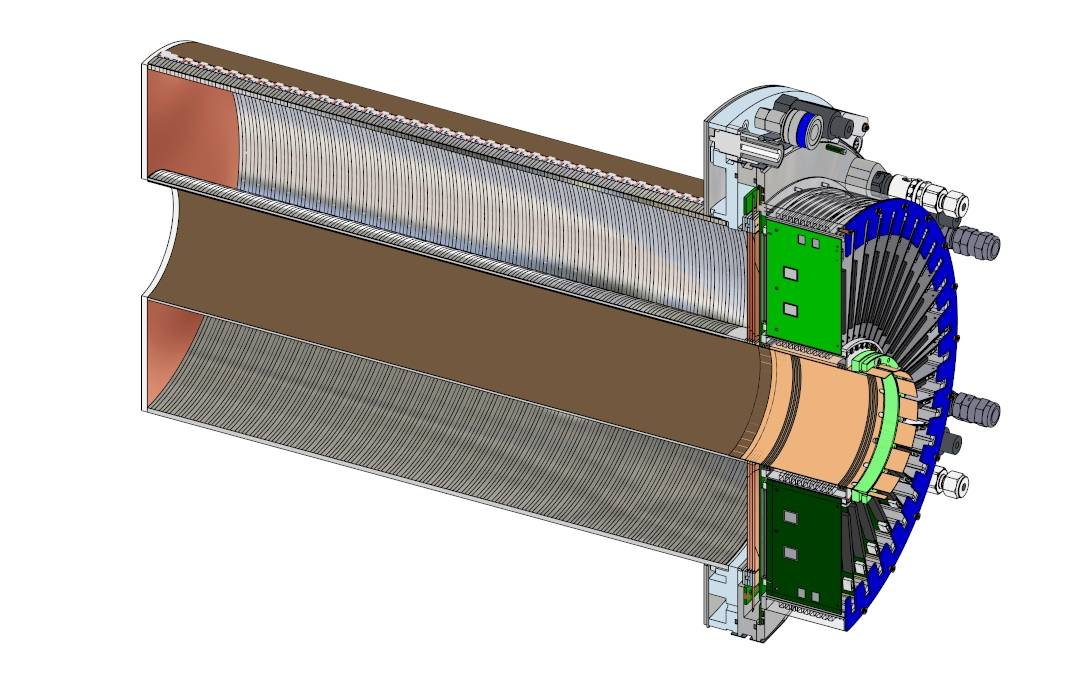
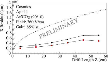
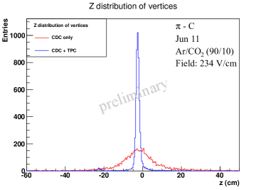
Figure 3 shows a cross section of the detector, which has a drift length of , and an inner (outer) diameter of (). Signals from the triple GEM amplification region are induced on 10254 hexagonal anode pads, chosen in order to optimize the spatial resolution for all possible track directions. The AFTER/T2K chip [13] is used to sample the analog signals at a frequency of . The detector has been commissioned with cosmics and particle beams at the FOPI experiment at GSI, and was recently employed for physics measurements with pion beams. The performance of the GEM-TPC, operated with a gas mixture of Ar/CO2 (90/10), fully matches the expectations with a spatial resolution of for small drift distances (Fig. 4), improving the momentum resolution of the existing spectrometer by and providing more precise vertex coordinates with a resolution of better than in direction. (Fig. 5).
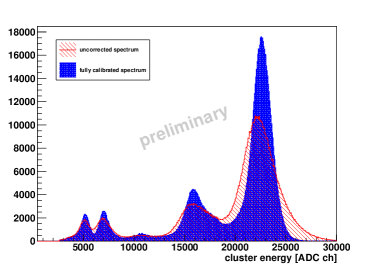
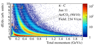
An important prerequisite for the measurement of the specific energy loss is the equalization of the gain across the active area of the detector. As in standard TPCs, this is achieved using decays of a 83mKr source introduced into the gas flow. Figure 6 shows the corresponding pulse height spectrum before and after gain equalization. An energy resolution of for the main peak is achieved in Ar/CO2, and similar values are obtained with a Ne/CO2 mixture. The first measurement of specific energy loss in a GEM-TPC over a wide momentum range is shown in Fig. 7, which has been obtained from data taken with a pion beam hitting a C target. The energy resolution depends on the number of samples along a track, and reaches for the longest tracks, in agreement with expectations [14].
4 The ALICE TPC Prototype
A substantial upgrade of the ALICE detector is foreseen until 2018 in order to fully profit from the increase of luminosity for the investigation of hot and dense matter using rare probes [3]. The upgrade also includes a replacement of the present gated MWPC-based amplification system of the TPC by GEM detectors, and a new continuous untriggered readout of the detector.
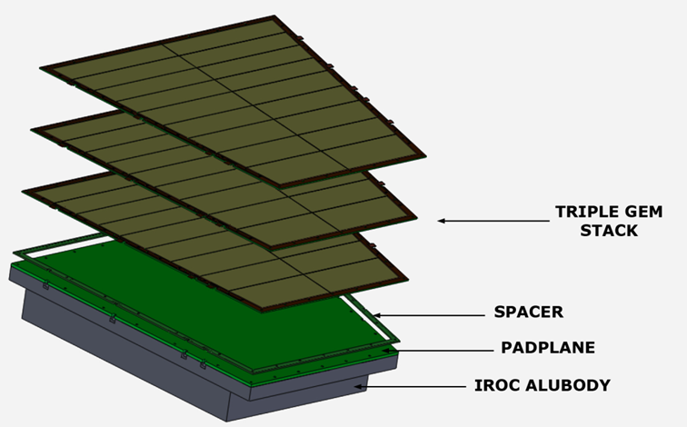
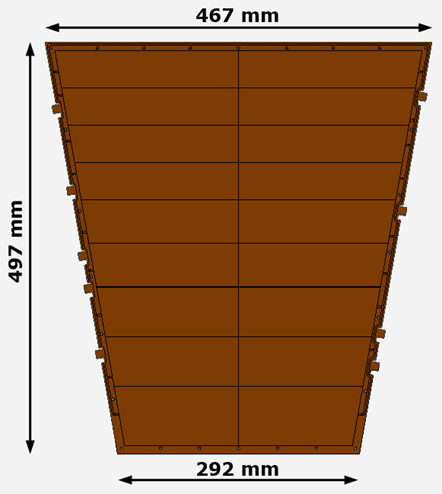
A first full-size prototype inner readout chamber (IROC) equipped with GEM foils has recently been designed and built (Fig. 8). The GEM foils are of trapezoidal shape of length and () width of the short (long) parallel sides, and have been manufactured at CERN using the newly developed single-mask technique [15]. They consist of 18 individually powered sectors on one side in order to optimize the high-voltage stability of the chamber. They have been glued on one side onto thick fiberglass frames with thin spacer grids matching the sector boundaries. A new stretching tool making use of pneumatic frames for a homogeneous distribution of forces has been introduced for this purpose.
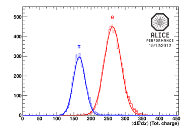
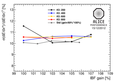
The GEM IROC was equipped with three GEM foils with transfer gaps and an induction gap of , matching the design of the FOPI GEM-TPC. For commissioning and testing the detector was placed in a test box equipped with a drift cathode and a field cage, providing a drift gap of . After testing with sources and cosmics, the detector was equipped with channels of readout electronics based on the PCA16 / ALTRO chips [16, 17] and installed in a beam line at the CERN PS. Beam particles (, , of momenta between and ) were identified using a Cherenkov and a lead glass detector. Figure 9 displays the energy loss distribution for electrons and negative pions measured in Ne/CO2 (90/10) with the GEM IROC prototype. A resolution of is obtained for pion tracks with a most probable value of samples, nearly independent of the gain between and , as can be seen in Fig. 10. For electrons, the resolution measured with the prototype is for all gain settings. These results are already in very good agreement with the value of measured for IROCs in the present TPC.
5 Conclusions
A GEM-based TPC opens the possibility of using the powerful features of such a detector in high-luminosity environments, without the limits of a gating grid. It also presents challenges both to the detector and to the readout due to the extreme amount of data produced. A large GEM-TPC was built and successfully operated in the FOPI experiment at GSI, fully meeting the requirements such as improved momentum and vertex resolution, and yielding the first measurement of specific energy loss with such a device in a physics experiment. The ALICE experiment at CERN plans to replace the MWPC-based readout of the TPC with GEM detectors during the LHC shutdown in 2017/2018. A first prototype IROC was equipped with a triple GEM stack and performed well during a beam test, confirming the good energy resolution of such a device. Issues currently being studied in Ne/CO2-based gas mixtures are the stability of a GEM detector in the harsh LHC environment, and the minimization of the ion backflow. The design of a first prototype GEM OROC (Outer Readout Chamber) is currently ongoing.
References
- [1] D. R. Nygren, et al., Phys. Today 31N10 (1978) 46.
- [2] J. Alme, et al., Nucl. Instr. Meth. A 622 (2010) 316.
- [3] ALICE Collaboration, L. Musa, et al., Letter of intent for the upgrade of the alice experiment, Tech. Rep. CERN-LHCC-2012-012. LHCC-I-022, CERN, Geneva (Aug 2012).
- [4] F. Sauli, Nucl. Instr. Meth. A 386 (1997) 531.
- [5] F. Sauli, et al., IEEE Trans. Nucl. Sci. 50 (2003) 803.
- [6] S. Blatt, et al., Nucl. Phys. B (Proc. Suppl.) 150C (2006) 155.
- [7] F. Böhmer, et al., arXiv:1209.0482 [physics.ins-det] (2012).
- [8] S. Bachmann, et al., Nucl. Instr. Meth. A 479 (2002) 294.
- [9] R. Veenhof, Garfield - simulation of tracking detectors, http://garfieldpp.web.cern.ch (2012).
- [10] A. Lyashenko, et al., Nucl. Instr. Meth. A 598 (2009) 116.
- [11] GEM-TPC Collaboration, L. Fabbietti, et al., Nucl. Instr. Meth. A 628 (2011) 204.
- [12] GEM-TPC Collaboration, M. Ball, et al., arXiv:1207.0013 [physics.ins-det] (2012).
- [13] P. Baron, et al., IEEE Trans. Nucl. Sci. 55 (2008) 1744.
- [14] W. Allison, et al., Ann. Rev. Nucl. Part. Sci. 30 (1980) 253.
- [15] S. Duarte Pinto, et al., Journal of Instrumentation 4 (2009) P12009.
- [16] R. Esteve Bosch, et al., IEEE Trans. Nucl. Sci. 50 (2003) 2460.
- [17] A. Kaukher, et al., EUDET-Memo-2009-08, EUDET-Memo-2009-08 (2009).