Modeling vitreous silica bilayers
Abstract
Theoretical modeling is presented for a free-standing vitreous silica bilayer which has recently been synthesized and characterized experimentally in landmark work. While such two-dimensional continuous random covalent networks should likely occur on energetic grounds, no synthetic pathway had been discovered previously. Here the bilayer is modelled using a computer assembly procedure initiated from a single layer of a model of amorphous graphene, generated using a bond switching algorithm from an initially crystalline graphene structure. Each bond is decorated with an oxygen atom and the carbon atoms are relabeled as silicon, generating a two dimensional network of corner sharing triangles. Each triangle is transformed into a tetrahedron, by raising the silicon atom above each triangular base and adding an additional singly coordinated oxygen atom at the apex. The final step in this construction is to mirror-reflect this layer to form a second layer and attach the two layers to form the bilayer. We show that this vitreous silica bilayer has the additional macroscopic degrees of freedom to form easily a network of identical corner sharing tetrahedra if there is a symmetry plane through the center of the bilayer going through the layer of oxygen ions that join the upper and lower monolayers. This has the consequence that the upper rings lie exactly above the lower rings, which are tilted in general. The assumption of a network of perfect corner sharing tetrahedra leads to a range of possible densities that we characterize as a flexibility window; with some similarity to flexibility windows in three dimensional zeolites. Finally, using a realistic potential, we have relaxed the bilayer to determine the density and other structural characteristics such as the Si-Si pair distribution functions and the Si-O-Si bond angle distribution, which are compared with experimental results obtained by direct imaging.
pacs:
61.43.Fs, 68.60.Bs, 68.35.bj, 68.55.J-I Introduction
The continuous random network model of network glasses is widely accepted as a model for materials like vitreous silica and amorphous silicon Thorpe Wright .
Although it is more than eighty years since Zachariasen proposed this model of glasses Zach , and experimental evidence has been compelling over the years, especially through diffraction experiments Thorpe Wright , it has never been quite conclusive since the probability distribution of rings of various sizes has been elusive to determine explicitly experimentally. This situation has now changed dramatically with the discovery and imaging lichtenstein2012 ; huang2012 of two dimensional bilayers of vitreous silica. Here, not only the distribution of rings, but the actual detailed atomic ring structure has been imaged for the first time in real space, removing all speculation from this subject (at least for this class of materials). These are the first examples of which we are aware of real space imaging of a random network and as such represent tours de force. Previously only small defect patches have been imaged, as for example for graphene as reported by Geim Geim .
In this paper, we provide the first atomic level computer model for a vitreous silica bilayer and demonstrate some intriguing and unexpected features that are shown to agree with experiment. There is a symmetry plane through the center of the bilayer where all the oxygen atoms that connect the tetrahedra in the lower and upper planes of the bilayer lie. Each tetrahedron comprises an SiO4 unit and the whole bilayer is a perfect corner-sharing continuous random network with the same chemical formula SiO2 as bulk vitreous silica. Each monolayer is amorphous with rings from 4 up to about 9 in size, consistent of course with Euler’s theorem that the average ring size is 6. Because of the amorphous nature of the monolayer and the need for oxygen bridges connecting the upper and lower layers, it is necessary for the two layers to have the same ring structure and be topologically identical to form a complete corner sharing tetrahedral network. The result that the two layers are also geometrical mirror images of each other is quite surprising at first sight in a system that is a priori without any symmetry, but comes about from understanding the nature of the constraints within the network as explained later. This is consistent with our detailed atomic modeling and also is in accord with the experimental results lichtenstein2012 ; huang2012 which show that the upper and lower layers do lie one on top of the other as required by a symmetry plane. We note that this does not imply that there is a three fold axis between the two upper and lower tetrahedral units (tetrahedral pair) through the common central oxygen atom - rather this Si-O-Si angle through the central oxygen has a distribution of values throughout the sample, as do all the other Si-O-Si angles in the bilayer.
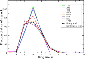
Thin vitreous SiO2 films (interpreted as bilayers) have been grown on Mo(112) weissenrieder2005 , Ru(0001) lichtenstein2012 ; heyde2012 ; loeffler2010 and graphene huang2012 . Figure 1 shows the experimentally-obtained ring statistics from references lichtenstein2012 and huang2012 . A key observation is that the ring statistics obtained from the two experimental samples are not the same, although this is not surprising in view of their different preparation conditions, analogous to various fictive temperatures used to characterize the preparation conditions for bulk silica Thorpe5 . Different Monte Carlo annealing temperatures and/or protocols used computationally to create vitreous silica bilayers also lead to different ring statistics similar to those documented previously in amorphous cellular networks Aste99 and in amorphous graphene kumar2012 .
What is unclear is the extent to which these differences in ring statistics reflect the finite system sizes under study or the more complex and more interesting dependence of the structure on the precise preparation conditions (including the nature of the substrate). The ring statistics are a fundamental quantity and their dependence on sample size imaged and on preparation conditions will be an important area for future study, especially experimentally. The simplest non-trivial (second cumulant) measure of the ring statistics should be related to the static structure factor , as in bulk vitreous silica Thorpe5 .
Recent simulation work, in which amorphous Graphene (a-G) configurations were generated using both bond-switching Monte Carlo and molecular dynamics methods, highlights how networks constructed primarily from 5-, 6- and 7-membered rings may adopt a range of structures kumar2012 . A useful simple metric for distinguishing between the different samples is the second moment of the ring size distribution,
| (1) |
where is the mean ring size for an ideal two-dimensional network constructed from purely three-coordinated sites ( from Euler’s theorem). This metric conveniently captures the major changes in ring statistics from sample to sample in a single number. The values of for the experimental data presented in Figure 1 are 0.904 and 0.886 (from References lichtenstein2012 and huang2012 respectively).
II Flexibility window
A key concept that will emerge is that there is a flexibility window involving motions among the rigid corner-sharing tetrahedra. This flexibility window designates a range of densities over which a framework of rigid tetrahedra, freely jointed at all corners with a given topology, can exist. The low density end of the window is defined by the maximum extension the framework can sustain without breaking apart, and the high density end of the window is determined by oxygen-oxygen overlap between adjacent tetrahedra. We will see that when additional terms are included in the potential, particularly the Coulomb terms, a particular density is selected from within the flexibility window. Similar ideas have been explored extensively in zeolites Thorpe2 where the origin of the window is due to symmetry as in the vitreous silica bilayers studied here. However, in bulk zeolites the symmetry is associated with the rotations and translations of the unit crystallographic cell, whereas here the symmetry is due to a reflection symmetry, that is maintained between the two monolayers that comprise the bilayer. We will return to a full analysis of this latter point in a later section.
III Construction method
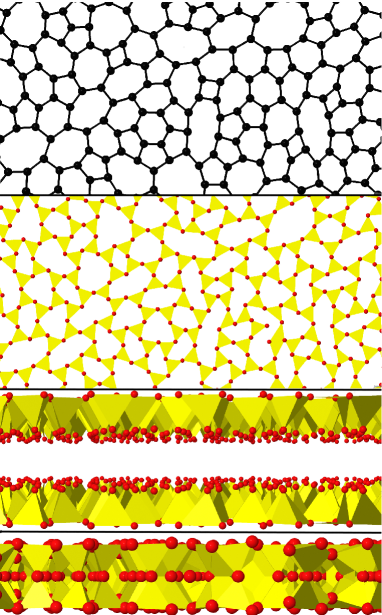
The initial SiO2 bilayer configurations are generated from ideal a-G coordinates (Figure 2), which were themselves generated using a “bond-switching” Monte Carlo algorithm (as described, for example, in Reference kumar2012 ; see also Aste99 ). The a-G configurations generated in this manner are guaranteed to be constructed exclusively from three-coordinated carbon local environments. This method is superior to others in the sense that it produces no coordination defects or dangling bonds, and is periodic with a super-cell whose size can be chosen and varied. Seed a-G configurations were constructed with a range of different ring statistics and hence values. Several different network sizes were employed. For convenience we shall refer to these systems below by their sizes, =120, 200, 400, 432 [two configurations, distinguished as (a) and (b)], 834, 836 and 1792 atoms. The two configurations containing 432 carbon atoms are generated with different ring statistics to give some extra perspective on the effect of the ring distribution on physical properties. Table 1 lists the values of for these a-G configurations, while Figure 1 shows the detailed ring size distributions for these computer generated structures.
| 120 | 0.467 |
|---|---|
| 200 | 0.500 |
| 400 | 0.480 |
| 432a | 1.046 |
| 432b | 0.935 |
| 834 | 0.618 |
| 836 | 0.856 |
| 1792 | 1.014 |
| expt. lichtenstein2012 | 0.904 |
| expt. huang2012 | 0.886 |
The method for generating the bilayers is motivated by the observation that the two layers sit on top of each other. As a result, each layer can be generated from the a-G configuration and joined with oxide anion bridges. To generate the initial SiO2 bilayer configurations, each carbon atom is transformed into a silicon atom (which will eventually become the center of each SiO4 tetrahedron). Oxygen atoms are then placed at the center of each C-C bond to produce a single layer configuration of stoichiometry Si2O3 confined to (say) the plane, which can be viewed as a two dimensional network of corner sharing equilateral triangles. Each triangle has oxygen atoms at the vertices and a silicon (transformed from carbon) atom at the center. Additional oxygen atoms are then placed perpendicular to the plane (which initially contained all of the atoms) at the center of each triangle and raised above to form a tetrahedron, with the silicon atom raised out of the plane to be at the center of the tetrahedron. This generates an Si2O5 network formed from tetrahedra; each sharing three corners with a fourth corner unshared (for the moment) and with all unshared corners pointing up. The second layer of the bilayer is created by producing a mirror image of the first layer (such that the tetrahedra are now pointing in the down direction) and offsetting the layer along the -direction, to lie above the first bilayer; see Figure 3(c). Finally, the median oxygen atoms are coalesced between the two layers giving the required SiO2 bilayer stoichiometry [Fig 3(d)]. The system super-cell lengths are then re-scaled so as to generate the required Si-O bond lengths. As a result, the systems considered contain [=240, 400, 800, 864(a), 864(b), 1668, 1672 and 3584] SiO2 molecules.
These structures are relaxed using standard Molecular Dynamics (MD) procedures with appropriate model inter-ion potentials. Two forms of potential model are considered. The first, which we will refer to as the harmonic potential, is designed to produce a corner sharing network of identical regular tetrahedra, with freedom of the individual tetrahedra to move and tilt with respect to each other while maintaining the topology. This allows for hinging-freedom of the joined tetrahedral corners, and does not impose reflection symmetry. A convenient way to accomplish this is to use harmonic springs to join the four nearest-neighbor Si-O and six nearest-neighbor O-O atoms in individual tetrahedron. Computationally the ratios of the O-O and Si-O equilibrium bond lengths of the potentials are chosen so as to produce ideal tetrahedra in isolation; thus the equilibrium separation for the neighboring oxygens along the edge of the tetrahedron in the O-O potential is taken to be times that for the Si-O nearest neighbor separation. For computational convenience the spring force constants are taken to be equal for both the Si-O and O-O pairs within each tetrahedron. The detail of this interaction is only significant in the sense of allowing for a relatively rapid energy minimization.
These simple harmonic potentials do not however, preclude different tetrahedra from overlapping, as would be the case in reality, for example to prevent oxygen overlap, and as limits the motions in zeolites Thorpe2 . In order to prevent this in a computationally convenient manner, the harmonic potential is augmented with a purely repulsive potential which acts between pairs of silicon atoms effectively acting as an inter-tetrahedron repulsive term.
The physically more realistic imposition of a short-range repulsion between oxygen atoms requires greater computational accounting. The chosen form is a shifted 24-12 potential,
| (2) |
where is the atom diameter and is the well-depth of the (unshifted) potential. The potential is cut off at the minimum [] ensuring continuity in both energy and force. The parameter is fixed while can be varied to explore the extent of the flexibility window. In the second form a more realistic potential model (a TS potential tangney2002 ) is used in which pairwise-additive potential energy terms (including ion-based charge-charge electrostatic interactions) are augmented with a description of (many-body) polarization effects tangney2002 ; wilson1996 ; madden1996 . This potential is more realistic than the harmonic potentials plus repulsions, mainly because Coulomb terms are included which are known to be important in ionic materials Thorpe2 and we use this for a further optimization of the bilayer structure. Nevertheless the harmonic potential plus repulsions is useful as the language of flexibility windows and constraints and the symmetry plane can be used, as is discussed in the next section.
We believe the choice of potential model is not crucial in displaying potentially interesting phenomenology in systems of this type. The harmonic potential is chosen as (arguably) the simplest model which constrains the system to form a series of ideal linked tetrahedral units. The TS potential is chosen as a potential which accounts well for a number of key (bulk) properties whilst retaining a relatively simple functional form.
Anion polarization, which controls the Si-O-Si bond angles in models of this type, may be crucial in defining the structures adopted both for silica and potentially for other, chemically-related, systems. Whilst the structures formed are low dimensional, the atoms retain their full (bulk) coordination so it is reasonable (at least in the first approximation) to apply potentials derived by reference to bulk three dimensional properties. These will most probably need further refinement as more precise experimental results on the vitreous silica bilayers become available.
We are very concerned with variation of the number density (number of SiO2 molecules per unit area) or, equivalently, the area occupied by a single molecule. The number density, , is expressed in terms of SiO2 units per unit area projected onto the central plane of the bilayer, whilst the area, , is expressed by reference to an ideal value, , which is the area occupied by a crystalline sample, based on crystalline graphene, in which all the tetrahedral pairs are aligned vertically with a three fold axis about the central oxygen ion, and which would be obtained from bilayers constructed from an ideal crystalline graphene sheet containing only six-membered rings.
Energy minimizations are performed over a range of dimensionless reduced areas . Note that is the maximum possible area which can be attained without strain (i.e distortion within the individual tetrahedra). At each density, the system’s energy is minimised using a steepest descent method. The atom positions are allowed to evolve, controlled by standard Newtonian mechanics, and the velocities are reset to zero (quenching the kinetic energy) when the kinetic energy reaches a (local) maximum. In order to allow explicitly breaking of the initial imposed reflection symmetry between the bilayers, several simulations are performed with randomized starting locations.
IV Results
In Figure 4, we show comprehensive results for the harmonic and the, TS potential. These results are given for two different samples (derived from the 200 and 432a atom a-G samples, so containing a total of 1200 and 2592 atoms respectively), in the two panels to give some perspective on the universality of the results. These two configurations are chosen as examples of systems with relatively high and low ring distribution variances (Table 1). The results for the harmonic potential that describes the corner sharing network of rigid tetrahedra are shown by the red, blue and green lines and show a distinct flat region for both samples that is the manifestation of the flexibility window. These three curves are generated by different values of , with the smaller values of , leading to larger flexibility windows. The flexibility window exists over a similar range of densities for both samples. It should be noted that the high density limit of the flexibility window is defined by repulsive potentials between the Si ions in this model, rather than the more physical repulsion between the larger O ions that is expected physically. However repulsion between the Si ions is expected to closely approximate the O-O repulsion, as the tetrahedra are all rigid. The low density limit, defined as the lowest the density can be without breaking the network of corner sharing tetrahedra, is where almost all zeolites are found experimentally. This is because when a more realistic potential than the harmonic potential is used, Coulomb inflation maximises the pore volume, and hence the sample volume Thorpe2 . The high density limit in zeolites is determined by that density at which interpenetration of the oxygen atomic spheres would onset. A similar situation is found here for vitreous silica bilayers, with a well defined flexibility window. This is in contrast to the case of three dimensional vitreous silica (no pores) where the flexibility window collapses to a single point (single density) Thorpe2 .
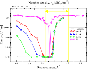
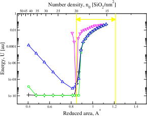
Figure 4 also shows the energies obtained by minimising the energy of the 400 and 864 SiO2 molecular bilayers using the TS potential. The energies resulting from the use of this potential function show sharp minima (when plotted on a logarithmic scale used here). These potentials produce a unique conformational minimum just below the high area limit of the flexibility window (obtained with the harmonic potential).
Figure 4 also shows the energies plotted against density; the harmonic potential results are scaled by the Si-O bond length (1.6). Also shown is the density range obtained from experiment cornell_pc . For both configurations, studied with all potentials, the harmonic potentials predict structures of slightly higher density than those observed preliminarily experimentally. On the other hand, for both these configurations the energy minima for the TS potential do lie within the currently observed experimental density range ( and SiO2/nm2 for the 400 and 864 molecule configurations respectively). The higher densities possible using the harmonic potential compared to the TS are to be expected due to the lack of electrostatic interactions which act to push the silicon cations apart. It is significant to note that the two configurations studied in depth produce energy minima with the TS at different densities implying the density to be a function of the atomistic detail (ring structure) of the bilayer configuration.
Figure 5 shows the Si-Si Radial Distribution Functions (RDFs) obtained for both the harmonic and TS potentials for both the 400 and 864 molecule configurations. The RDFs are calculated by projecting the Si-Si separations onto the plane (and hence mimicking the experimental procedure). Energy minimisation using the TS potential produces structures with order beyond the nearest-neighbor length-scale of the same form as that generated by the harmonic potential. The first peak (corresponding to the nearest-neighbor Si-Si length-scale) appears considerably sharper for the TS potential, reflecting the ordering imposed by the presence of the electrostatic interactions. The reduced intensities in the molecule system compared with the molecule one reflects the higher degree of disorder in the former (as characterised by their respective values of ).
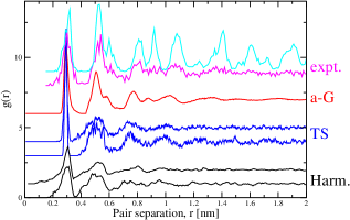
Figure 5 also shows the experimentally-determined functions (from Reference cornell_pc ) obtained for both a crystalline and an amorphous section of bilayer. The analysis of the experimental data remains very preliminary, and a much better determination of the density will be possible once larger areas of the samples are imaged. For the moment the fairly wide estimates of the experimental density cornell_pc are shown by the yellow lines in Figure 4. These wide estimates are obtained from the relatively small field of view of the vitreous silica bilayers currently available, and we await larger fields of view from which a more accurate density can be obtained. Note this density is obtained directly from the atomic imaging cornell_pc . The density is a very important parameter to know, both in regards to the flexibility window and for detailed validation of the potentials used here. It is quite possible that the potentials we have used will have to be fine tuned later to reflect the experimental density but for the present we are concentrating principally on the conceptual physics. The preliminary experimental RDF shown in Figure 5 is broadly consistent with all the model structures in this paper, and data from much larger experimental areas should discriminate between the nuances of various computer generated structures.
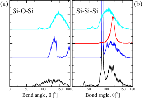
Figure 6(a) shows the Si-O-Si Bond Angle Distributions (BADs) determined for the harmonic potential (at for which the energy could be driven to zero), and at the energy minimum determined from the TS potential for the 400 molecule system. The Si-O-Si BAD determined with either form of the TS potential is significantly narrower than that determined from the harmonic potential, reflecting the higher degree of ordering imposed by the presence of the electrostatic interactions. The harmonic distribution shows a major peak at of width 25o while the TS shows a peak position (width) of 132o (15o). Note that the removal of anion polarization terms from the TS potential (to generate a rigid-ion model) results in a peak position (width) of 150o (10o). The change in the peak position in the bond angle distribution is consistent with the inclusion of anion polarization which acts to effectively screen the Si-Si (repulsive) electrostatic interactions and hence stabilises more acute Si-O-Si bond angles. The distribution appears very different from that obtained for the bulk glass using the TS potential wezka2013 (also shown in Figure 6) which shows a broader distribution (50o) with a peak at consistent with experiment neuefeind1996 . Note that in an unrelaxed crystalline bilayer, based on a crystalline graphene seed with a median symmetry plane, the Si-O-Si bond angle is cos142o within a monolayer and 180o between monolayers. It is interesting to note that 142o is very close to the chemically preferred Si-O-Si bond angle in the absence of any topological strains due to rings navrotsky . The component at lower angles in the middle blue panel in Figure 6(a) is associated with in-plane angles and the other peak with angles involving both planes. In the other two panels in Figure 6(a), there is only a single very broad peak.
| Potential | / | ||||
| upper | lower | center | |||
| 400 | harm. | 0.81 | 0.124 | 0.124 | 3.910-14 |
| harm. | 1.00 | 0.087 | 0.087 | 2.810-14 | |
| 864 | harm. | 0.81 | 0.184 | 0.184 | 4.010-14 |
| harm. | 1.00 | 0.137 | 0.137 | 3.910-14 | |
| 400 | TS | 0.92 | 0.151 | 0.151 | 7.210-14 |
| 864 | TS | 0.85 | 0.274 | 0.274 | 9.010-14 |
The difference between the bilayer and bulk BADs can be rationalised as follows. The mirror symmetry relationship between the top and bottom layers of the bilayer means that ions of the same charge sit on top of one another perpendicular to the plane containing the bilayer. As a result, the (repulsive) like-like electrostatic interactions are effectively maximised, leading to relatively obtuse Si-O-Si bond angles centred about the oxygen ions which bridge the two layers, and resulting in the peak at 175o. A simple geometric argument indicates that the presence of these relatively obtuse angles has a knock-on effect for the Si-O-Si angles centred about the oxygen ions which are in one of the bilayer planes, which will be relatively acute. This is an area that needs more study as there will always be a competition between the preferred Si-O-Si angles from chemistry and the requirements of the network topology. This effect will influence whether similar vitreous bilayers can be made from germanium and also whether aluminum ions can be alloyed with silicon ions in these vitreous silica bilayers.
Figure 6(b) shows the Si-Si-Si bond angle distributions obtained using the harmonic and the TS potentials at the same densities as in Figure 6(a). The results are compared to the C-C-C BAD generated from the original a-G configuration. Recall that for crystalline graphene the bond angle is 120o. The bilayer BADs show a sharp peak at 90o which corresponds to Si-Si-Si triplets in which the Si atoms are split between the two layers comprising the bilayer, while the higher broader peak corresponds to in-plane Si. The harmonic and TS potentials show similar distributions which are significantly broader than the a-G distribution.
To quantify the presence of a mirror plane after relaxation, which does not impose any symmetry, we determine the variance of the oxygen atom positions () perpendicular to the bilayer plane. The oxygen atoms can be considered as sitting in three distinctive quasi-planes corresponding to the central layer (which joins the two original monolayers) and the two layers above and below this central layer. Table 2 lists the variances for the 400 and 864 SiO2 molecule systems obtained using the harmonic potential (at two densities) and the TS (in the respective energy minima densities). The central atoms are clearly confined to a single plane while the atoms in the upper and lower layers show identical variances. The existence of the mirror plane is confirmed by determining the variance in the positions of the mirrored atoms in the upper and lower planes which is to within the numerical precision used. In principle the mirror symmetry can be broken once the potential contains Coulomb terms etc., as the argument given in the section Symmetry Planes based upon constraints does not hold with more complex forces. However in practice it seems these deviations are very small, although in principle present. We also note that this symmetry in the perpendicular to the bilayer plane, holds not only at the macroscopic 9(average) level, but also at the local level between corresponding atoms above and below the central symmetry plane.
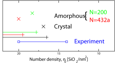
The most important results of this section, and paper, are summarised in Figure 7 where the flexibility windows and corresponding energy minima for the two amorphous and one crystalline sample are shown. It should be noted that the TS minima lies within the flexibility window as expected. In addition it lies towards the top, high area end, of the window reminiscent of the relationship observed in zeolites Thorpe5 . The argument given for the zeolites was that Coulomb inflation in the pores between the negative oxide ions caused the sample to swell to be very close to the maximum allowed while remaining inside the flexibility window. Such an argument cannot be given here, as there are no large pores as in zeolites - but we propose that Coulomb inflation, between the oxide ions, may still be the explanation within the rings of the bilayer. The silicon ions are less important as they are smaller. However we do not find this argument entirely convincing, and more work on understanding the subtleties of the effects of Coulomb interactions in ionic framework structures is needed.
V Symmetry plane
The existence of a symmetry plane in an amorphous sample is surprising and quite unlike anything that we have encountered before. This symmetry emerges from the disordered state as the network takes advantage of the larger conformational space available when a symmetry plane is present compared to without. Hence symmetry is induced in a system which at first sight seems a canonical example of a system without symmetry. The argument for it is compelling as outlined here, and confirmed both by detailed atomic computer modeling and by experiment. Of course the individual tetrahedral units are close to perfect tetrahedra because of the strong local chemical bonding, but these pack in a disordered way. The local symmetry of perfect tetrahedra is not necessary for the argument for the symmetry plane to hold. Residual degrees of freedom in a structural unit are often referred to as floppy modes Thorpe .
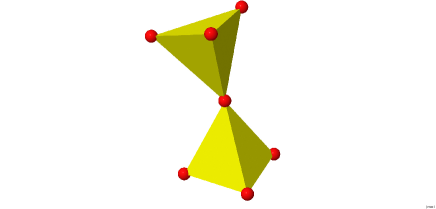
Consider two tetrahedral units (which we will call a tetrahedral pair) with a common oxygen atom - that is Si2O7 as shown in Figure 8. There are such units made from the units of SiO2 in the bilayer structure. A rigid body has 6 degrees of freedom in three dimensions, and for any two vertices of adjacent tetrahedra to coincide requires 3 constraints ( x1 = x2, y1 = y2 and z1 = z2, where 1 and 2 refer to the two tetrahedral vertices that come together). We now give counting arguments Thorpe for the case without symmetry and then with symmetry between the bilayers from a (proposed) reflection plane in the middle of the two layers.
1. Without symmetry. Consider the two separate tetrahedra in the tetrahedral pair shown in Figure 8; each with the usual 6 degrees of freedom for a rigid body in three dimensions. That makes 12 degrees of freedom in total. Joining the common oxygen atom requires 3 constraints (to make the tetrahedral pair) and the 6 remaining oxygen ions each require 3 constraints, which are shared so that there are floppy modes, which is the expected result that the system is isostatic Thorpe2 - that is the structure just has enough constraints to be rigid and cannot be moved (subject to the usual remarks about boundary conditions etc. Thorpe4 ). This result is expected as the bilayer is just a special case of a network of corner sharing tetrahedral units which are all isostatic Thorpe2 . This can be seen easily as each individual isolated tetrahedron has 6 degrees of freedom, and four shared corners each with 3 constraints - hence the number of floppy modes per tetrahedron is and we have an isostatic network; that is no floppy modes.
2. With symmetry. First define an external plane and position it at . Then move a single tetrahedron so one vertex lies in this plane but is free to move in the plane. This tetrahedron initially has 6 degrees of freedom, and putting an atom somewhere in the external plane requires a single constraint. The 3 other oxygen atoms require constraints to link the corners - the second tetrahedron in the tetrahedral pair is fixed by the reflection symmetry and therefore has neither independent degrees of freedom nor independent constraints associated with it. Thus there are remaining degrees of freedom for each tetrahedral pair and hence a total of degrees of freedom for the whole bilayer.
The important observation here is that with corner sharing tetrahedra, there are a macroscopic number of degrees of freedom if there is a reflection plane. This allows the bilayer structure to roam over a region of conformational space while maintaining all the constraints. This leads to a flexibility window analogous to that found previously in zeolites Thorpe2 . As discussed later, we find that with a more realistic potential the bilayer settles within the flexibility window at a preferred density. This is a pretty remarkable and unexpected result.
The above arguments can be streamlined and made very compact. Looking at the lower monolayer, disconnected from the upper monolayer, then if there is a reflection plane only a single constraint is required at each oxygen that is not shared with another tetrahedron in order to bring it to the reflection plane, whereas three shared constraints would be required to bring it into coincidence with a similar oxygen in an otherwise unconstrained second monolayer. Adding the mirror monolayer adds no extra degrees of freedom. Therefore a reflection plane leads to a macroscopic number of floppy modes .
Yet another distinct demonstration of this result can be given as follows. Start with planar collection of corner-sharing triangles. There are degrees of freedom and constraints giving no remaining degrees of freedom. That is such a network (example is a kagome lattice) is isostatic and only flexible if there is a surface and (O) floppy modes. Now consider a flexible framework of tetrahedra connected with the same topology of corner sharing triangles (each tetrahedron has three connected corners), then there are degrees of freedom and constraints giving a macroscopic number of degrees of freedom . If further, the remaining vertex of each tetrahedron, so fixing one of its Cartesian coordinates, then the total number of degrees of freedom per tetrahedron is . Adding the reflected monolayer to the original monolayer gives SiO2 units with degrees of freedom for the bilayer, as before.
Note that these arguments apply to tetrahedra of arbitrary shape and size, so if there are some Al ions within tetrahedra in the lower layer at some composition, they should be mirrored in the upper layer based on the arguments in this sections, although Coulomb repulsions between them would discourage this. Aluminum and silicon tetrahedra are both nearly perfect but have different sizes Thorpe2 and so attempting to construct such bilayers would be something interesting to try experimentally. The situation is very different in conventional zeolites, where Loewenstein’s empirical rule Lowen for alumino-silicates states that (in essence) every Al - containing tetrahedra must be connected to four neighboring silicon-containing tetrahedra. It is possible, therefore, that Loewenstein’s rule could sometimes be violated in bilayer structures.
VI Conclusions
We have shown how the recently discovered vitreous silica bilayer can be computer-modeled by progressive assembly, starting from an amorphous graphene sheet, and making various decorations and then relaxation with appropriate potentials. This pathway is of course not physical, but represents a convenient way of computer-generating such structures.
This system is probably the first network glass where the ring structure can be experimentally observed directly by STM and STEM measurements with atomic resolution, making it a paradigm system for future study. This present study provides a complementary computer-theoretical study that we hope will encourage further experimental and theoretical work.
An interesting observation is the unexpected mirror symmetry plane through the center of the bilayer, which seems to defy the logic which says that such bilayers should pucker. The fact that the top monolayer lies exactly on top of the lower monolayer, means that a single layer is seen in the experimental STEM image, making structural interpretations much easier, and confirming the symmetry argument given here. This is a very unusual situation of a symmetry induced in a disordered system. However it should be noted that such a reflection symmetry is also expected in crystalline silica bilayers, where it is less surprising. Although additional terms in the potential, like the Coulomb terms, may result in this symmetry being broken, this is not observed in the experiments, or in the computer simulations, at the current level of accuracy. It should be noted that amorphous graphene shows no such symmetry and is expected to show considerable puckering, unless constrained from doing so by a sufficient applied tension kumar2012 .
VII Acknowledgments
We should like to thank Mike Treacy for many useful discussions including those relating to Lowenstein’s rule and the US National Science Foundation for support under Grant No. DMR-0703973. We should also like to thank Pinshane Huang and David Muller for sharing their experimental data. DS acknowledges support from the Leverhulme Trust through an Emeritus Research Fellowship.
References
- (1) M.F. Thorpe and A. Wright Eighty years of random networks. Phys. Status Solidi B, 1-6, 10.1002/pssb.201248500 (2013)
- (2) W. H. Zachariasen The Atomic Arrangement in Glasses. J. Am. Chem. Soc. 54, 3841 (1932)
- (3) L.Lichtenstein, C. Buechner, B.Yang, S.Shaikhutdinov, M.Heyde, M.Sierka, R.Wlodarczyk, J.Sauer, and H-J Freund. The atomic structure of a metal-supported vitreous thin silica film. Angew. Chem. Int. Ed., 51:404 (2012)
- (4) P.Y.Huang, S.Kurasch, A.Srivastava, V.Skakalova, J.Kotakoski, A.V.Krasheninnikov, R.Hovden, Q.Mao, J.C.Meyer, J.Smet, D.A.Muller, and U.Kaiser. Nano. Lett., 12:1081 (2012)
- (5) A.K. Geim Graphene: status and prospects Science, 324, 1530–4 (2009)
- (6) J.Weissenrieder, S.Kaya, J-L. Lu, H-J.Gao, S.Shaikhutdinov, H-J. Freund, M.Sierka, T.K.Todorova, and J.Sauer. Atomic structure of a thin silica film on a Mo(112) substrate: A two-dimensional network of SiO2 tetrahedra. Phys. Rev. Lett., 95:076103 (2005)
- (7) M.Heyde, S.Shaikhutdinov, and J.J Freund. Two-dimensional silica: Crystalline and vitreous. Chem. Phys. Lett., 550:1 (2012)
- (8) D.Loffler, J.J.Uhlrich, M.Baron, B.Yang, X.Yu, L.Lichtenstein, L.Heinke, C.Buchner, M.Heyde, S.Shaikhutdinov, H.J.Freund, R.Wlodarczyk, M.Sierka, and J.Sauer. Growth and structure of crystalline silica sheet on Ru(0001). Phys. Rev. Lett., 105:146104 (2010)
- (9) Adam M.R. de Graff and M.F. Thorpe The long-wavelength limit of the structure factor of amorphous silicon and vitreous silica. Acta Cryst. A 66, 22-31 (2010)
- (10) T.Aste and D.Sherrington. Glass transition in self-organizing cellular patterns J. Phys. A: Math. Gen., 32: 7049 (1999)
- (11) A.Kumar, M.Wilson, and M.F.Thorpe. Amorphous graphene: a realization of Zachariasen’s glass. J. Phys.: Condens. Mat., 24:485003 (2012)
- (12) A. Sartbaeva, S.A. Wells, M.M.J. Treacy and M.F. Thorpe The flexibility window in zeolites. Nature Materials 5, 962-965 (2006); See also commentary 931-932
- (13) P.Tangney and S.Scandolo. J. Chem. Phys., 117:8898, 2002.
- (14) M.Wilson, P.A.Madden, M.Hemmati, and C.A.Angell. Phys. Rev. Lett., 77:4023 (1996)
- (15) P.A.Madden and M. Wilson. Chem. Soc. Rev., 25:339 (1996)
- (16) P.Y.Huang, S.Kurasch, A.Srivastava, V.Skakalova, J.Kotakoski, A.V.Krasheninnikov, R.Hovden, Q.Mao, J.C.Meyer, J.Smet, D.A.Muller, and U.Kaiser. Private communication.
- (17) K.Wezka, D.A.J.Whittaker, P.S.Salmon, A.Zeidler, S.Klotz, H.E.Fischer, M.C.Wilding, C.L.Bull, M.G.Tucker and M.Wilson, submitted (2013)
- (18) J. Neuefeind and K.-D. Liss, Ber. Bunsen-Ges. Phys. Chem., 100, 1341 (1996)
- (19) K.L. Geisinger, G.V. Gibbs and A. Navrotsky Physics and Chemistry of Minerals, 11, 266-283 (1985).
- (20) M.F. Thorpe Flexibility and Mobility in Networks. Encyclopedia of Complexity and Systems Science, Ed. by Robert A. Meyers, Springer, New York, Volume 5, pages 6013-602) (2009)
- (21) Vitaliy Kapko, M.M.J. Treacy, M.F. Thorpe and S.D. Guest On the Collapse of Locally Isostatic Networks. Proc. Roy . Soc. A, 465, 3517-3530 (2009)
- (22) W. Lowenstein The distribution of Alumina in the tetrahedra of silicates and aluminates. Am Minerals 39, 92-98 (1954)