Optical reflectivity and magnetoelectric effects on resonant plasmon modes in composite metal-multiferroic systems
Abstract
The rôle of the magnetoelectric effect upon
optical
reflectivity is studied by adapting an
electrodynamic-based model for a system composed
by a 2D
metallic film in contact with an extended
multiferroic
material exhibiting weak ferromagnetism. The
well-known
Nakayama’s boundary condition is
reformulated by
taking into account the magnetoelectric coupling
as well
as an externally applied magnetic field
in an
arbitrary direction. It is found that the reflectance shows strong fluctuations for incident radiation close to the characteristic antiferromagnetic resonance frequency associated with the multiferroic material in the THz regime. These results were verified for a 10 nm metallic foil by using a finite element method (FEM) and the Rouard’s approach, for a wide range of wavelengths (0.1 - 5 mm), showing good agreement with respect to Nakayama’s outcome, for the particular material BaMnF4.
Keywords: Multiferroics, Magnetoelectric
effect, Surface Plasmon, Reflectance.
DOI: PACS numbers: 73.20.-e,75.82.+t, 78.20.Bh, 78.66.Bz
I INTRODUCTION
Magnetoelectric (ME) effects in multiferroic (MF) or ferromagnetic (metallic) films have brought remarkable interest since promising technological applications in spintronics and ultrafast electric field control on magnetic data storage are seen as imminentDuan ,Gerhard . Characterization of the relative strength for the ME coupling can be obtained by implementing terahertz spectroscopy in rare earth manganites of the type RMnO3 (R=Tb, Gd, Dy, Eu:Y) Pimenov ,Talbayev ,Nemec ,Pimenov2 demonstrating that the generated electromagnons (mixed spin-waves and photon states) represent, among others, the signature of the ME effect for an approximate range of frequencies between 10 cm-1 and 40 cm-1 at temperatures where antiferromagnetic resonance modes (AFMR) coexist, or more recently, the key mechanism for controllable magnetochromism in Ba2Mg2Fe12O22 hexaferrites Kida . The magnetoelectric effect emerges when a magnetic field can induce a polarization vector at zero applied electric field (). Likewise, the magnetization of the substance can be generated for an electric field with . The minimal coupling for describing the thermodynamic potential associated with this effect is given by , where is an unsymmetrical magnetoelectric tensor, whose components depend on the magnetic symmetry classLandau . The primary origin for the ME coupling is commonly associated with the Dzyaloshinskii-Moriya relativistic exchange-interaction Nagaosa ,Katsura0 which is appropriate for the description of asymmetric spin wave dispersion on double layer Fe-filmsZakeri as well as for those materials where weak ferromagnetism emerges, namely the ilmenite FeTiO3, TbMnO3, Eu1-xYxMnO3 ( at KMukhin ) or the widely studied pyroelectric ferromagnet BaMnF4 Scott . Weak ferromagnetism on this compound is generated by canting effects between antiferromagnetic sub-lattices, leading to a spontaneous polarization perpendicular to the resulting magnetization Gun . Considerations in the symmetry change of the static polarization and magnetization fields have brought interesting unconventional optical phenomena labeled as non-reciprocal dichroism associated with the sign reversal of , recently reported in the perovskite Eu0.55Y0.45MnO3, with magnetoelectric activity for photon energies around 0.8 meV (sub THz regime) in the cycloidal phase at 4 KTaka . Intense activity in the last decade has also been dedicated to achieve possible optical and photonic band gap control via Surface Plasmon (SP) propagation in periodic arraysBarnes , since modern lithographic techniques allow to design functional objects with almost any desirable geometrical pattern at a sub-wavelength scalegrooves . Plasmon localization and its coupling with incident light depend on the dielectric properties of the metal in conjunction of its surrounding environment, enlightening an alternative route for engineering highly efficient SP photonic devices via externally applied fields, rare earth doping or electron charge transference from the modified metalFreund . In this communication, we study an electrodynamic-based model for estimating the optical response generated by the contact between a material exhibiting weak ferromagnetism in contact with a 2D metallic film. It is found that a specific strength of the ME interaction might couple with localized charge-sheet modes for electron carrier densities about cm-2 and incident frequencies around 18 cm-1, leading to a change in the reflectance from the metallic film. Applied magnetic field effects on relative reflective are discussed in section III.
II MODEL
Localized charge-sheet modes in a 2D conducting medium in the framework of Drude approximation is obtained from the Nakayama result Nakayama ,Cottam ,Pitarke :
| (1) |
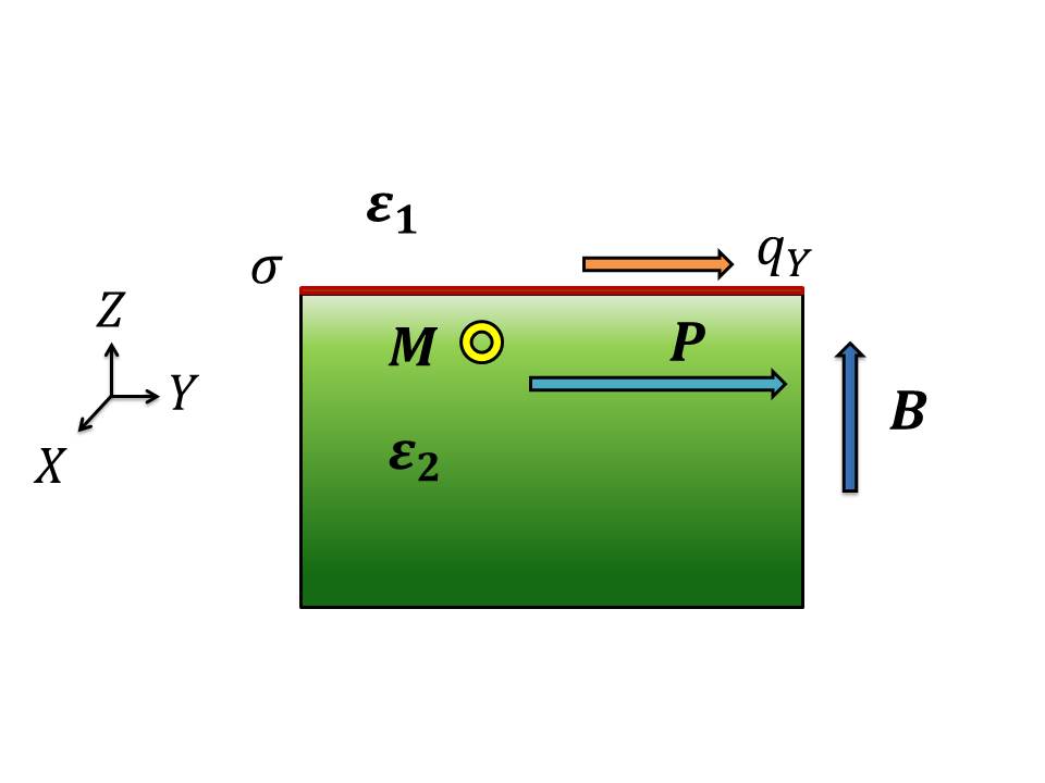
where corresponds to the quasiwavevector in the direction, is defined as and denotes the electron density concentration in a two dimensional space. is related with the wavevector along -direction through , (). The term represents the relative dielectric function value for -th medium, with for vacuum. In the range of wavelengths behind the far infrared radiation ( mm), the dielectric function approaches to the well recognized Lyddane-Sachs-Teller (LST) relationship: , where corresponds to the dielectric permittivity of the medium and represents the longitudinal (transverse)-optical phonon frequency. For numerical purposes, we have set , which coincides with the relationship for the -axis normal phonon modes in BaMnF4. The permittivity is a functional depending on mechanical strain deformations and polarization field depletion in the proximities between the multiferroic slab and metal filmAlpay , and is taken as constant for zero applied (electric) field and fixed temperature. Formula (1) is derived by solving the complete set of Maxwell equations with normal (TM wave) incidence for , and boundary conditions on the plane with the ansatz for propagating fields in the region . Magnetoelectric effects are taken into consideration throughout the transverse susceptibility and the electric displacement vector is written into the constitutive equation like . After inserting the additional term , the expression (1) shall be modified under . In the plane , and in agreement with the geometrical configuration shown in Figure (1), the non-zero surface current density component is defined as , where corresponds to the -element of the generalized conductivity tensorSolyom , and is the electrical field propagating on the direction.
The generic expression for the transverse susceptibility is obtained from first principles by minimizing the free-energy density functional , which contains the two sublattice magnetizations, the polarization as well as external fields. Tilley ,Stamps . It can be summarized as: , where is a coupling parameter which is an involved function of the canting angle between two adjacent (antiferromagnetic) sublattices, the spontaneous magnetization and the polarization vector , as well as the parameters . Factor is defined in terms of the characteristic magnetoelectric frequency as , given in units of mm-2 all throughout this paperRivera , in concordance with the spectral weight intrinsically associated with the fitting procedure for the transmittance spectra via Lorentzian model in various multiferroic species, namely RMn2O5(R:Y,Tb), TbMnO3 or LuMnO3Sushkov , and its dependence with the externally applied magnetic field has been neglected for small canting angles (See for instance Eqs. (38) and (47) in reference [14]. Two main poles are clearly identified for : the optical antiferromagnetic resonance mode (AFMR) and the soft-phonon along with resonance frequency , with . Classical plasmon excitations in low 2D carrier electron density are experimentally detected and theoretically estimated for wavevectors cm-1 and energies meVSarma , Chulkov0 ,Kanjouri , therefore the condition remains valid in the range of interest, and the dispersion relationship for the coupled magnetoelectric plasma mode is obtained by solving the modified equation (1):
| (2) |
with , and . For , i.e., no magnetoelectric effects taken under consideration, we reproduce the expression for the localized plasmon mode Nakayama :
| (3) |
where () sign in equation (2) has been selected. Complex index of refraction is directly estimated from the wavenumber fowles . The lowest-order reflectance coefficient for normal incidence is defined as and its numerical profile discussed on the next section. can be considered as the effective index of refraction for the composite 2D metallic foil in contact with a multiferroic (ferroelectric) system under normal incidence of a electromagnetic wave oscillating in the THz regime. Applied magnetic field B along -direction enters into the formalism by taking symmetry considerations upon the dependence of the electrical conductivity as a function of B under the transformation , with . Expression (2) may be reconstructed as:
| (4) |
with . The classical localized magnetoplasmon mode (3) is rewritten for and under likeEriksson :
| (5) |
in similarity with the result (3). In this particular case the antireflective condition () depends on the external magnetic field intensity , which leads to a quadratic correlation for . For an arbitrary orientation of , equation (1) shall be modified on its right side accordingly , where is a function of the directors magf . Optical reflectivity response for this structure might also be verified by adapting the Rouard methodLecaruyer ,Heavens :
| (6) |
where corresponds to the internal reflectivity between media labeled () and is the phase difference on the second medium with thickness , defined as . The index of refraction is a function of the components for the conductivity tensor depending on the incoming electromagnetic field polarization. In this particular case, it is calculated as:
| (7) |
while is explicitly given by
where represents the electronic plasma frequency for the bulk system, which is related to through where being the volumetric electron density concentration. Reference values for plasma frequencies were taken as Hz and Hz for gold (Au) in the framework of the Drude model fittingws . Factors in formula (6) are given explicitly by , and , with . Indeces of refraction are directly obtained by reconstructing the set of Maxwell equations on each material media. In the general case, taking into account the ME effect in the formalism by inserting the tensor , the propagating electric field must satisfy:
| (8) | |||
where is the conductivity tensor, and previously defined as the electric displacement vector, and subscript indicates the region where fields propagation are evaluated, namely the metal (M) or multiferroic (MF) slab.
III RESULTS AND DISCUSSION
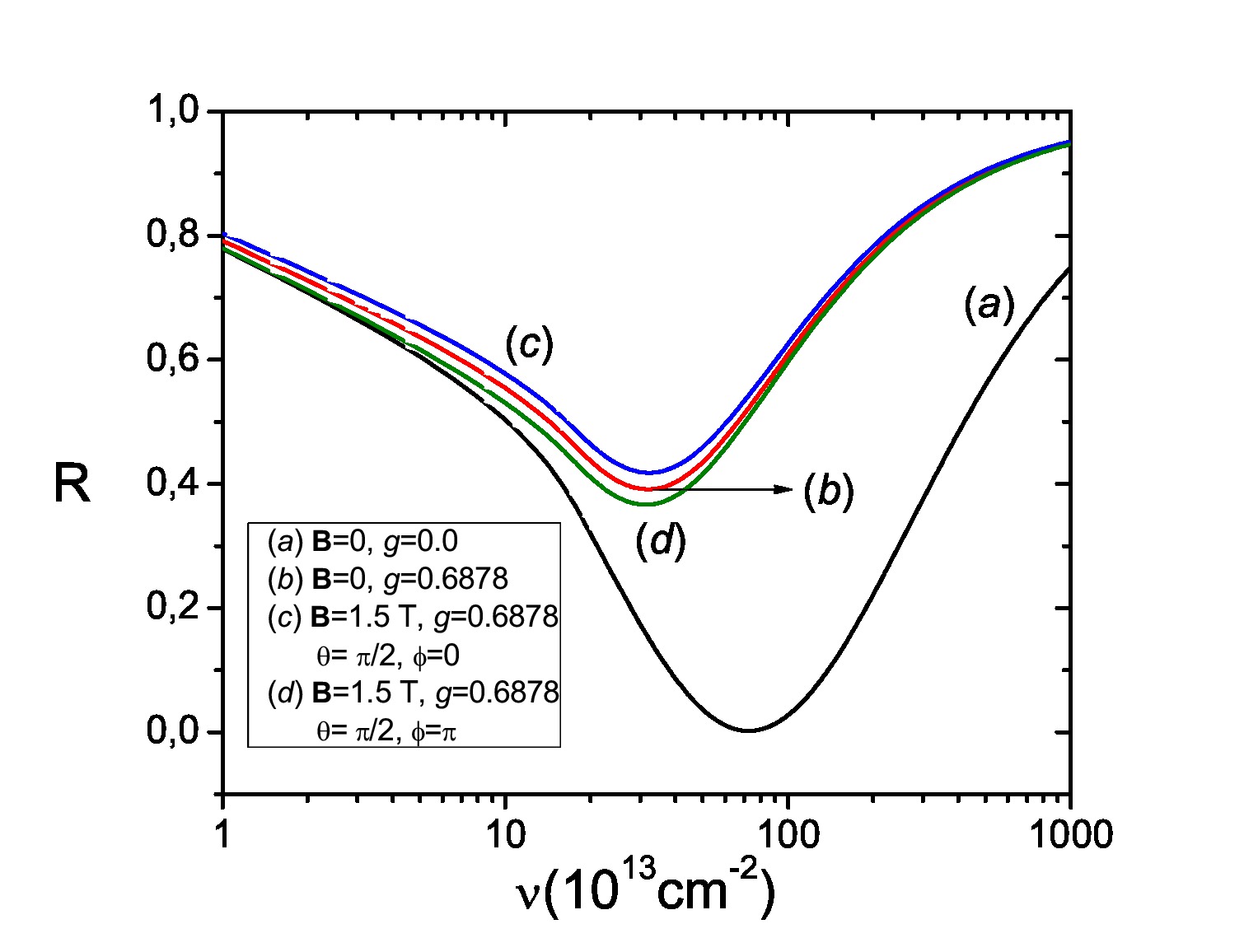
Figure (2) exhibits the zero field reflectance response as a function of the 2D electronic carrier concentration , for different wavelengths and the magneto-electric coupling parameter fixed at mm-2, the dielectric permittivity values have been taken as and for the pyroelectric ferromagnet BaMnF4, which correspond to the values measured along its and crystallographic axes, respectively. Dotted curves (a) and (b) are set as reference for . Comparative results are shown for Rouard’s method (RM) and the modified Nakayama (N) expression (Eq. 1), indicating the change in the reflectivity spectra under the ME effect and different values for the dielectric constant . The reflectance response increases from () to () for electronic densities lower than cm-2, while it augments monotonically to for electronic concentrations greater than cm-2 regardless of the value of , in the framework of the RM approach. One of the discrepancies with the Nakayama results is due to the difference between the 2D intrinsic plasma frequency and those associated with the plasma frequency in the bulk system . Variation in the electronic carrier density in the former case has been simulated by inserting the thickness film dependence on , providing good agreement for nm ( cm-2) as proven in Fig.(6). Minima of reflectivity obtained from Eq. (2), are located at , or , indicating that the critical wavelength for bare plasmon excitations is larger as the electronic concentration decreases. AFMR mode lies in the range THz range, with THz, while the transverse phonon frequency is taken as 7.53 THz for the BaMnF4 compoundBarnas . Metallic behavior predominates for concentrations higher than cm-2 and smaller than cm-2 and selected wavelengths between 0.5 mm and 0.6 mm. Resonant plasmon modes (i.e., collective electronic excitations under ME interaction) are important for carrier densities around cm-2, where radiative absorption or antireflective phenomena become strong and the reflectance spectrum is therefore significantly modified by diminishing the percentage of absorbed radiation only when the external frequency approaches the characteristic mode , and .
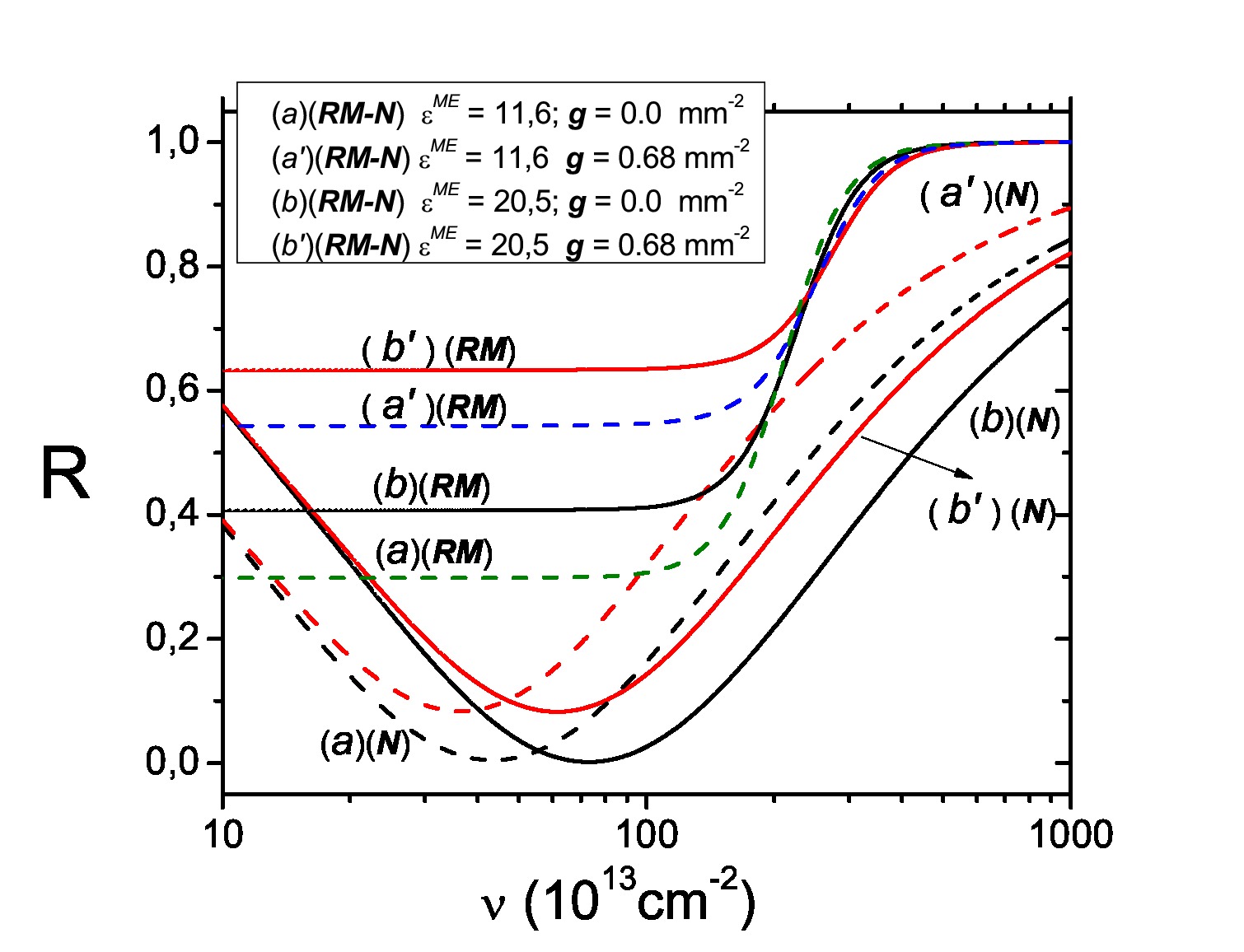
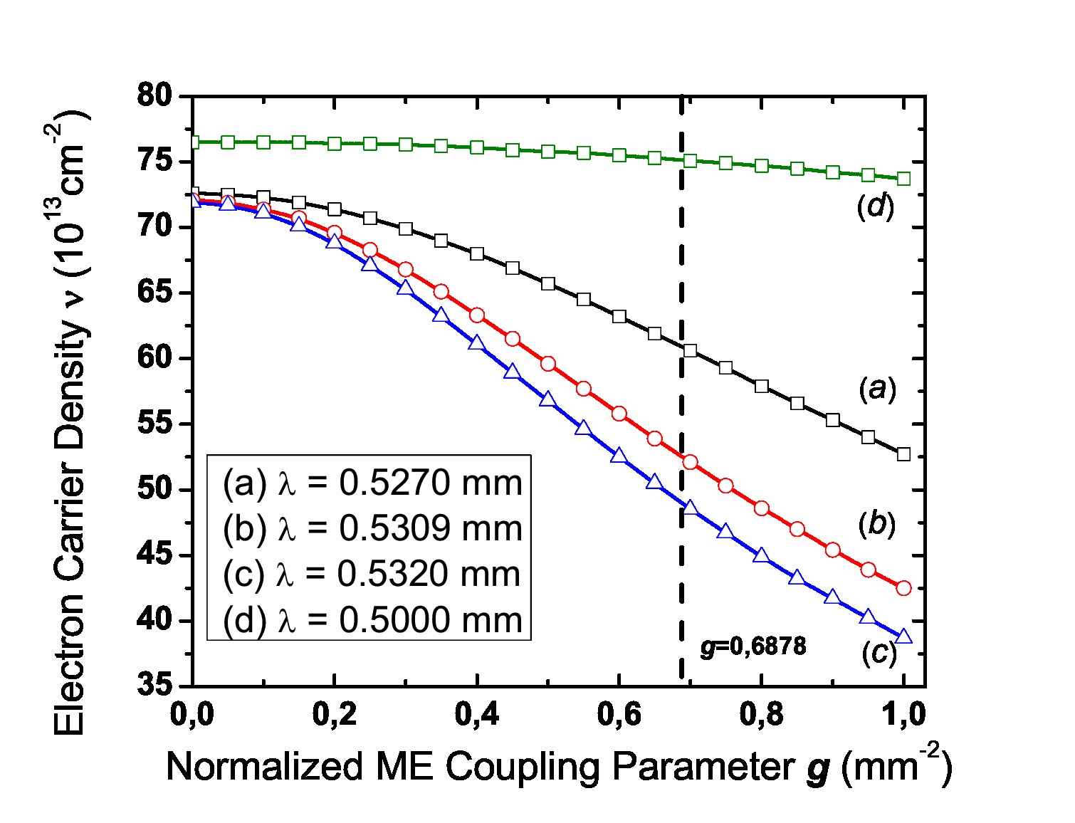
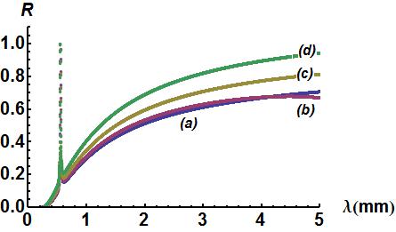
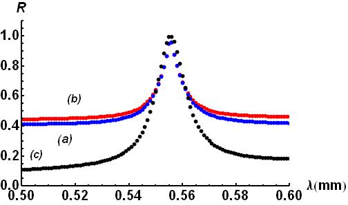
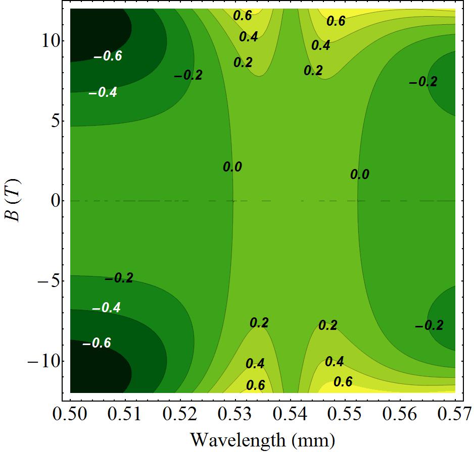
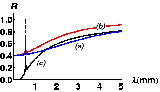
Figure (3) depicts the shifting of the minimum of reflectance in the plane for the Nakayama approach. The ME effect becomes relevant by decreasing the critical carrier density as increases, and it remains essentially unmodified for those frequencies away from the AFMR characteristic mode as indicated in line (d). Dotted vertical line is tagged at mm-2 as a eye guide for identifying the critical density change as the incident wavelength varies around . Critical density shall be understood as the electron carrier concentration which maximizes antireflective effects for the composite metal/multiferroic system. Figure (4) shows the reflectance response under applied magnetic field with magnitude T for different directions on the plane. AFMR resonance at is not essentially affected by the orientation of the external field, but it becomes sensitive with the azimuthal angle for frequencies between the edge of the THz range and the microwave (SHF) band. Highly reflective effects are more intense for external magnetic fields which are applied in the opposite direction with respect to the weak ferromagnetic state , favoring the metallic behavior for long wavelengths and shielding the resulting ME interaction. In-plane applied field effects on the reflectance as a function of carrier density are illustrated in Fig. (5). tends to increase for parallel to -axis and decreases for along axis. Curve (b) for null overlaps the outcome of at T, and (i.e., parallel to axis), indicating no substantial variation in the optical reflectance for applied fields in the same direction of the plasmonic wavevector for carrier densities smaller than cm-2. Equation (8) has also been treated by implementing Finite Element Method (FEM) and standard boundary conditions for and fields in order to calculate the reflectance response as a function of incident wavelengths. Comparative results on the calculated response of the reflectance are shown in figures (6) and (8). Under Nakayama’s formalism, the metallic medium is treated as a 2D system, while Rouard and FEM methods converge with the first one for a film thickness around nm, which roughly corresponds to an electronic carrier density of 147.42 cm-2 after calculating the correlation between two intrinsic plasma frequencies and . Iso-reflective lines for JDE close to and the externally applied magnetic field (in direction) are shown in Figure (7). Projected lines preserve symmetrical distribution under magnetic field inversion nearby although strong fluctuations and a sign flip on are present for wavelengths slightly different from and magnetic fields greater than T, indicating that interacting ME and plasmonic activity might increase the reflectance outcome from systems with low electronic density and without applied field.
IV CONCLUDING REMARKS
We have developed a model for studying the
magnetoelectric interactions on 2D plasmonic modes in the THz
range for a metal/multiferroic composite device. The multiferroic
medium exhibits weak ferromagnetism and the metallic
behavior enters into the formalism in the framework of the classical Drude-Lorentz model. Relative reflectance response for normal incidence is numerically calculated
for a particular ME coupling strength and
wavelengths near to the optical antiferromagnetic resonance frequency
by using three different approaches: Nakayama’s formalism, Rouard’s method and Finite Elements (FEM). Characteristic soft phonon and AFMR frequencies were taken for the pyroelectric ferromagnet BaMnF4, showing that a particular condition for reflectivity might
be adjustable by varying the intensity of the applied field, its orientability, film thickness or incident frequency of radiation, mainly in a range . Spectra of reflectance demonstrate that the magnetoelectric interaction predominates for metallic film thicknesses smaller than 25 nm in the THz regime, while for thicker films (50-100 nm) the optical outcomes are not significantly affected by this interaction; instead, total reflectance from the film is observed along a wide range of frequencies up to the cut-off bulk value PHz, in which reflectivity decays abruptly to zero and exhibits oscillatory behavior for greater frequencies. The chosen value of is into the typical order of magnitude for good conductors like gold, silver or copper, despite that the calculations and comparison with the strictly 2D system were made just for the first one. There is not a clear signature of the plasmonic cut-off for intermediate film thicknesses (25-50 nm) and the reflectivity curve does not breach abruptly as for wider ones; rather, it reaches its maximum value in a broad interval of Hz, suggesting a variation of the effective dielectric response associated with the metal under ME interaction.
Further analysis shall be proposed for other metals or semiconducting materials, since optical control experiments on the THz range have recently been
achieved on GaAs wafers via stimulated
photocarriers generated by interband light absorption.
The resulting reflectivity spectrum is tuned from antireflective () to high reflective
() limits under controlled power illuminationFekete ,Coutaz . Although all numerical simulations were conducted
for , ( being taken as and in the range of interest), simultaneous electric field control
on optical properties for the
composite device might also be achieved under the dielectric
function dependence for a multiferroic material
,
the polarization
and temperature, issue that shall be addressed in
future investigations.
Acknowledgements.
H.V. wants to thank computing accessibility at POM group. C. V.-H. acknowledges financial support provided by DIMA, Dirección de Investigación Sede Manizales, Universidad Nacional de Colombia. H.V. declares no competing financial interest.References
- (1) C-G Duan, J. P. Velev, R. F. Sabirianov, Z. Zhu, J. Chu, S. S. Jaswal and E. Y. Tsymbal, Phys. Rev. Lett. 101, 137201 (2008).
- (2) L. Gerhard, T. K. Yamada, T. Balashov, A. F. Takács, R. J. H. Wesselink, M. Däne, M. Fechner, S. Ostanin, A. Ernst, I. Mertig and W. Wulfhekel, Nature Nanotechnology 5, 792 (2010). doi:10.1038/nnano.2010.214
- (3) A. Pimenov, A. M. Shuvaev, A. A. Mukhin and A. Loidl, J. Phys.: Condens. Matter 20, 434209 (2008).
- (4) D. Talbayev, S. A. Trugman, A. V. Balatsky, T. Kimura, A. J. Taylor and R. D. Averitt, Physical Review Letters 101, 097603 (2008).
- (5) H. Nmec, F. Kadlec, P. Kuel, L. Duvillaret and J.-L. Coutaz, Optics Communications 260, 175 (2006).
- (6) A. Pimenov, A. A. Mukhin, V. Yu Ivanov, V. D. Travkin, A. M. Balbashov and A. Loidl, Nature Physics 2, 97-100 (2006).
- (7) N. Kida and Y. Yokura, Journal of Magnetism and Magnetic Materials 324, 3512 (2012).
- (8) L. D. Landau, E. M. Lifshitz and L. P. Pitaevskii, Electrodynamics of Continuous Media, 2nd Ed., Ch.V, Butterworth-Heinemann (2006).
- (9) H. Katsura, N. Nagaosa and A. V. Balatsky, Physical Review Letters 95, 057205 (2005).
- (10) H. Katsura, A. V. Balatsky and N. Nagaosa, Physical Review Letters 98, 027203 (2007).
- (11) Kh. Zakeri, Y. Zhang, J. Prokop, T.-H. Chuang, N. Sakr, W. X. Tang and J. Kirschner, Physical Review Letters 104, 137203 (2010).
- (12) A. A. Mukhin, V. Yu Ivanov, V. D. Travkin, A. S. Prokhorov, A. A. Volkov, A. V. Pimenov, A. M. Shuvaev and A. Loidl, Phys.-Usp 52, 851 (2009). DOI: 10.3367/UFNe.0179.200908j.0904
- (13) J. F. Scott, Rep. Prog. Phys. 42, 1055 (1979).
- (14) V. Gunawan and R. L. Stamp, J. Phys.: Condensed Matter 23, 105901 (2011).
- (15) Y. Takahashi, R. Shimano, Y. Kaneko, H. Murukawa and Y. Tokura, Nature Physics 8, 121 (2012), doi:10.1038/nphys2161
- (16) W. L. Barnes, A. Dereux and T. W. Ebbensen, Nature 424, 824 (2003).
- (17) S. Li, M. Jadidi, T. E. Murphy and G. Kumar, Optical Express 21 No. 6, 7041 (2013).
- (18) H. J. Freund, Surface Science 601, 1438 (2007).
- (19) M. Nakayama J. Phys. Soc. Jpn.36, 393 (1974).
- (20) M. Cottam and D. R. Tilley, Introduction to Surface and Superlattice Excitations, Cambridge University Press (1989).
- (21) J. M. Pitarke, V. M. Silkin, E. V. Chulkov and P. M. Echenique, Rep. Prog. Phys. 70, 1-87 (2007).
- (22) S. Zhong, S. Alpay, V, Nagarajan, J. Mater. Res. 21 (6) (2006) 1600.
- (23) J. Sólyom, Fundamentals of the Physics of Solids, Vol. II, Springer-Verlag (2009).
- (24) D. R. Tilley and J. F. Scott, Physical Review B 25, 3251 (1982).
- (25) K. L. Livesey and R. L. Stamps, Physical Review B 81, 094405 (2010).
- (26) J.-P. Rivera, Eur. Phys. J. B. 71, 299 (2009).
- (27) A. B. Sushkov, R. Valdés Aguilar, S. Park, S-W. Cheong and H. D. Drew, Physical Review Letters 98, 027202 (2007).
- (28) E. H. Hwang and S. Das Sarma, Physical Review B 64, 165409 (2001).
- (29) I. A. Nechaev, V. M. Silkin and E. V. Chulkov, Journal of Experimental and Theoretical Physics 112, Issue 1, pp 134-139 (2011).
- (30) F. Kanjouri, A. H. Esmailian and M. Molayem, Eur. Phys. J. B 79, 429 (2011).
- (31) G. R. Fowles, Introduction to Modern Optics, Second Edition, Dover (1989); J. B. Marion and M. A. Heald, Classical Electromagnetic Radiation, Second Edition, Chapter 6, Academic Press (1980).
-
(32)
,
with
,
and , and . - (33) P. Lecaruyer, E. Maillart, M. Canva and J. Rolland, Applied Optics 45, 8419 (2006).
- (34) O. S. Heavens, Optical Properties of Thin Solid Films, Chapter 4, Dover Publications (1991).
- (35) E. J. Zeman and G. C. Schatz, J. Phys. Chem. 91(3), 634-643 (1987).
- (36) J. Barnaś, Journal of Magnetism and Magnetic Materials 62, 381 (1986).
- (37) M. A. Eriksson, A. Pinczuk, B. S. Dennis, C. F. Hirjibehedin, S. H. Simon, L. N. Pfeiffer, K.W. West, Physica E 6, 165 (2000).
- (38) J. D. E. McIntyre and D. E. Aspnes, Surface Science 24, 417 (1970).
- (39) L. Fekete, J. Y. Hlinka, F. Kadlec, P. Kuel and P. Mounaix, Optical Letters, 30, No. 15, 1992 (2005).
- (40) Recent developments in terahertz optoelectronics, Edited by Jean-Louis Coutaz, Comptes Rendus Physique, 9, Issue 2, Pages 127-284 (2008).