The ATLAS Inner Detector operation, data quality and tracking performance.
Abstract
The ATLAS Inner Detector is responsible for particle tracking in ATLAS experiment at CERN Large Hadron Collider (LHC) and comprises silicon and gas based detectors. The combination of both silicon and gas based detectors provides high precision impact parameter and momentum measurement of charged particles, with high efficiency and small fake rate. The ID has been used to exploit fully the physics potential of the LHC since the first proton-proton collisions at 7 TeV were delivered in 2009. The performance of track and vertex reconstruction is presented, as well as the operation aspects of the Inner Detector and the data quality during the many months of data taking.
1 Introduction
The Inner Detector (ID) [1] forms the tracking system for ATLAS experiment [2]. It is designed to reconstruct charged particle tracks and vertices, to measure the momentum of charged particles above a given transverse momentum () threshold and within the pseudorapidity range . The ID operates in a high fluence environment and to achieve required momentum and vertex resolution the detector granularity must be very fine. The ID consists of three types of tracking components (from innermost layer): Pixel Detector [3], SemiConductor Tracker (SCT) [4] and Transition Radiation Tracker (TRT) [5]. The three sub-detectors are contained within a cylindrical envelope of length 3512 mm and of radius 1150 mm, surrounded by a solenoid providing magnetic field of 2 T. Figure 1 illustrates the geometrical layout of the Inner Detector.
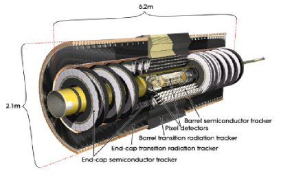
The Pixel Detector is situated the closest to the interaction point and has the highest granularity. In total there are about 80 million readout channels in the whole Pixel Detector. The intrinsic spatial resolution of individual Pixel Detector modules, is 10 m in and 115 m in . The SCT is a silicon detector with microstrips which surrounds the Pixel Detector layers. As track density decreases at larger radii, microstrip detectors can have fewer read-out channels. It is designed to provide 8 measurements per track with resolution of 16 m in and 580 m in . The TRT is the most outer part of ID. It provides a large number of tracking measurements (typically 30 hits per track), good pattern recognition and it contributes to particle identification. The TRT is a light-weight detector, composed of gaseous proportional counters (straws) embedded in a radiator material. The straws are filled with 70% Xe, 27% CO2 and 3% O2 gas mixture with 5-10 mbar over-pressure, for which the operational drift radius accuracy is 130 m.
2 Detector operations, data taking and data quality
LHC delivered an integrated luminosity of 5.6 fb-1 of proton-proton collision data at the center-of-mass energy of 7 TeV in 2010 and 2011. In 2012 the center-of-mass energy was increased to 8 TeV and the LHC luminosity was upgraded significantly. ATLAS recorded integrated luminosity of impressive value of 14.3 fb-1 by October 2012 [6]. The ID has been fully operational throughout all data taking periods and delivered excellent data taking performance. Luminosity weighted relative fraction of good quality data delivered during 2012 stable beams in pp collisions by the Pixel Detector, SCT, and TRT subsystems was 99.9%, 99,4% and 99,8% accordingly [7].
Such an excellent data taking performance was possible thanks to reliable and robust Data Acquisition Systems (DAQ) and Detector Control System (DCS). The Data Acquisition Systems of all ID sub-detectors have proved to be highly reliable with excellent data taking efficiency. During operation several enhancements were introduced into DAQ in order to avoid potential sources of inefficiency. One of the possible inefficiency sources are readout chip errors (e.g. spontaneous corruption of module configuration) caused by Single Event Upsets (SEUs). SCT introduced online monitoring of chip errors in the data and the automatic reconfiguration of the modules with errors. In addition, an automatic global reconfiguration of all SCT module chips every 30 minutes was implemented, as a precaution against subtle deterioration in chip configurations as a result of SEUs [8]. The main component in the DAQ is the Readout Driver Board (ROD), which provides the front-end data flow, data processing and control of the detector modules. If any ROD experiences an error condition, it will exert a BUSY signal to stop ATLAS data taking. In 2010, each subsystem implemented an automatic removal of a busy ROD from the ATLAS readout, thereby enabling ATLAS to continue data taking while the cause of the BUSY was corrected. Automatic re-integration of a recovered ROD was also implemented. An automatic re-synchronisation procedure of the TRT RODs was also introduced. This procedure is invoked during the LHC ramp and whenever synchronization is lost. It allows for the TRT to continue taking data without stopping and restarting the run.
The Detector Control System (DCS) supervises, besides the individual subsystems, ID detector components, provides information about conditions inside the detector, assures optimal working conditions and provides protection mechanisms. The main ID DCS subsystems are: Evaporating Cooling to keep silicon detector cooled to , Heater Pad systems that ensures thermal shield between silicon detectors and TRT operating in room temperature. There is also set of projects dedicated to beam condition monitoring and radiation doses monitoring inside ID volume. To protect the front-end electronics from the potentially harmful effects of beam incidents, the HV was only switched fully on for the Pixel Detector and SCT when stable beam conditions were declared. Outside of stable beams, the Pixel Detector HV was off, and the SCT was operated with reduced HV. In SCT and Pixel Detector DCS the automatic turn-on, so called ”warm start”, was implemented in order to maximize the time of data taking. Detectors were set automatically to ready-for-data-taking state immediately after stable beams were declared by LHC and beam parameters, measured by ID beam condition monitoring system, were correct. Typical time to ready for data-taking in silicon detectors was 1 minute.
3 Radiation Damage
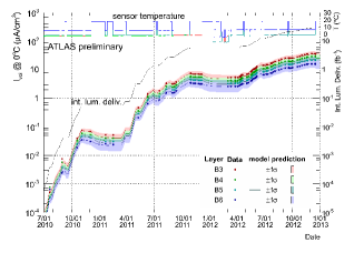
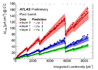
Radiation damage effects in SCT and Pixel Detector became visible in 2011 and they are increasing with luminosity and time. Significant increases in leakage currents have been observed in silicon detectors, as expected from bulk damage due to non-ionising radiation. Figure 2 shows SCT barrel leakage currents during 2010, 2011 and 2012, and evolution of high voltage current for Pixel Detector. The leakage current increase correlates closely with delivered luminosity and temperature cycles. This dependence is well-understood and agrees with leakage current predictions derived from the temperature profiles and fluence from FLUKA [11] simulations.
4 Track and vertex reconstruction performance
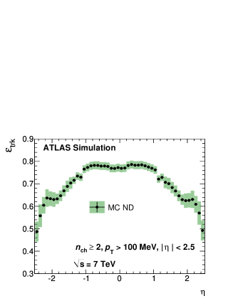
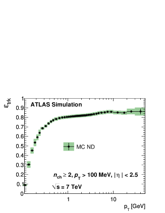
Tracks above a given threshold (nominally 0.4 GeV, however this value changes depending on the data) are reconstructed offline within the full acceptance range of the Inner Detector, using multi-stage track identification algorithms. The inside-out algorithm starts from silicon space point seeds and adds hits from neighboring silicon layers. The track candidates found in the silicon detectors are then extrapolated to include measurements in the TRT. It reconstructs most primary tracks. The outside-in algorithm starts from segments reconstructed in the TRT and extends them inwards by adding silicon hits. It reconstructs secondary tracks (e.g. conversions, hadronic interactions, decays). The track reconstruction efficiency is defined as the fraction of primary particles with MeV and matched to a reconstructed track. Figure 3 presents tracking efficiency for minimum bias analysis derived from simulation. Efficiency is highest at central region of rapidity and for tracks with high transverse momentum.
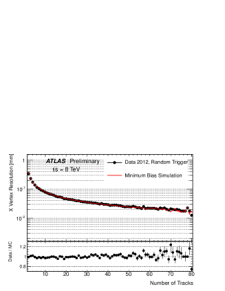
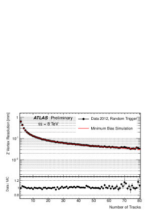
Primary vertices are reconstructed using iterative vertex finder algorithm. Well reconstructed charged tracks which are compatible with the interaction region are fitted to a common primary vertex. Then a is formed and the tracks which are displaced more than 7 from the vertex are used to search for the new vertices. The procedure is repeated until no additional vertices can be found. The beam spot is used as three-dimensional constraint in vertex finding algorithm and it is routinely determined from average vertex position over a short time period. Vertex resolution is derived from data using split vertex technique. Vertex position resolution in collision data from 2012 compared with Monte Carlo is presented on figure 4. There is a very good agreement at the level of 5% between data and simulation.
5 Tracking in High Pile-up
The luminosity delivered by LHC is the biggest challenge for tracking and vertexing, as the ID is particularly sensitive to the increase in particle multiplicity with pile-up. In 2012 the mean number of inelastic proton-proton interactions () per bunch crossing reached the number of approximately 30, which is beyond ID design specification. The increased detector occupancy can result in degraded track parameter resolution due to incorrect hit assignment, decreased efficiency and fake tracks from random hit combinations. This in turn impacts vertex reconstruction, resulting in a lower efficiency and an increased fake rate. With the data delivered up to date the track reconstruction efficiency is unchanged. However, when using the track quality requirements developed for high efficiency in low pile-up conditions, the fraction of combinatorial fakes increases with [14]. The fake track fraction in high pile-up data can be suppressed by applying tighter quality requirements on reconstructed track, called robust track selection . With the robust requirements fake track fraction is reduced by a factor of 2-5 and becomes almost independent of the amount of pile-up, but there is moderate drop in primary track reconstruction efficiency (2-5%), which is independent of [14]. The probability of reconstructing fake vertices increases with pile-up. While at low pile-up its value is below 0.1%, it increases up to 7% at = 41 when vertices are reconstructed with tracks passing the default requirements. It can be controlled with negligible efficiency loss by applying robust requirements on the tracks used in vertex reconstruction [14].
6 Alignment
Precise detector alignment is required to obtain ultimate track parameter resolution. The ID is aligned using a track based method [15], which relies on the minimization of a constructed from track-hit residuals (residual is the difference between the reconstructed track and the actual hit in the detector). The alignment is performed at 3 different levels of granularity corresponding to the mechanical layout of the detector: Level 1 corresponds to entire sub-detector barrel and end-caps of Pixel Detector, SCT and TRT. Level 2 deals with silicon barrels and discs, TRT barrel modules and wheels. Level 3 aligns each silicon module and TRT straws having 700,000 degrees of freedom in total. Level 1 alignment is performed automatically on run-by-run basis. The studies on 2011 data show limited movements of Level 1 structures which usually can be correlated to sudden change in detector conditions, e.g. temperature. There exist systematic detector deformations e.g. distortion, that cannot be detected using the approach described above as they retain the helical form of tracks at the same time biasing the track parameters. Advanced alignment methods using Z resonance and for electrons are used to remove residual biases on momentum reconstruction [16].
7 Conclusions
The ATLAS Inner Detector has been fully operational throughout all LHC data taking periods. The operational efficiency of all sub-systems is excellent and tracking performance meets or exceeds design specifications.
References
- [1] ATLAS Collaboration, Eur.Phys.J. C70 (2010) 787-821.
- [2] ATLAS Collaboration, JINST 3 S08003 229 (2008).
- [3] G. Aad et al., JINST 3 P07007 (2008).
- [4] J. Carter et al, Nucl. Instrum. Meth. A578 98-118 (2007).
- [5] ATLAS TRT Collaboration, J. Instrum. 3 (2008) P02013.
- [6] https://twiki.cern.ch/twiki/bin/view/AtlasPublic/LuminosityPublicResults
-
[7]
https://twiki.cern.ch/twiki/bin/view/AtlasPublic/
RunStatsPublicResults2010 - [8] D. Robinson, ATL-INDET-PROC-2012-002.
- [9] https://twiki.cern.ch/twiki/bin/view/AtlasPublic/SCTPublicResults
- [10] https://twiki.cern.ch/twiki/bin/view/AtlasPublic/ApprovedPlotsPixel
- [11] A. Ferrari, P. Sala, A. Fasso and J. Ranft, “FLUKA: A multi-particle transport code“, CERN-2005-10 (2005), INFN/TC-05/11, SLAC-R-773.
- [12] ATLAS Collaboration, New J. Phys. 13, 053033 (2011).
-
[13]
http://atlas.web.cern.ch/Atlas/GROUPS/PHYSICS/IDTRACKING/
PublicPlots/ATL-COM-PHYS-2012-474 - [14] ATLAS Collaboration, ATLAS-CONF-2012-042.
- [15] ATLAS Collaboration, ATLAS-CONF-2011-012.
- [16] ATLAS Collaboration, ATLAS-CONF-2012-141.