Spiral graphone and one sided fluorographene nano-ribbons
Abstract
The instability of a free-standing one sided hydrogenated/fluorinated graphene nano-ribbon, i.e. graphone/fluorographene, is studied using ab-initio, semiempirical and large scale molecular dynamics simulations. Free standing semi-infinite arm-chair like hydrogenated/fluorinated graphene (AC-GO/AC-GF) and boat like hydrogenated/fluorinated graphene (B-GO/B-GF) (nano-ribbons which are periodic along the zig-zag direction) are unstable and spontaneously transform into spiral structures. We find that rolled, spiral B-GO and B-GF are energetically more favorable than spiral AC-GO and AC-GF which is opposite to the double sided flat hydrogenated/fluorinated graphene, i.e. graphane/fluorographene. We found that the packed, spiral structures exhibit unexpected localized HOMO-LUMO at the edges with increasing energy gap during rolling. These rolled hydrocarbon structures are stable beyond room temperature up to at least =1000 K.
pacs:
73.23.-b, 73.21.La, 72.15.Qm, 71.27.+aI Introduction
The discovery of graphene geim has been a driving force for the scientific community to synthesize and to characterize new materials with similar morphologies due to their unique properties 10 ; silice ; APL2011 ; novoselov . Fully double sided hydrogenated graphene (GE), i.e. graphane (GA), and double sided fluorographene are quasi two-dimensional lattices of carbon (C) atoms ordered into a buckled honey-comb sublattice, where each carbon atom is covalently bonded to hydrogen (H) or fluor (F), respectively, in an alternating, chair-like arrangement sluiter-sofo ; expF . The chemisorption of hydrogen and fluor atoms results in an important reconstruction of the chemical bonds and angles of the underlying honeycomb lattice mehdi . This transition from sp2 to sp3 hybridization turns the graphitic C-C bonds into single bonds by the formation of additional single C-H and C-F bonds, which change locally the planar shape of graphene into an out of plane, angstrom scale buckled geometry PRB77 .
Experimentally, it has been shown that GA can be obtained reversibly starting from a pure GE layer in the presence of atomic hydrogen elias . It has become an interesting material due to its potential applications in nanoelectronics int2 . On the other hand, the experimentally obtained single-layer fluorographene exhibits a strong insulating behavior with a room temperature resistance larger than 1 T, and a high temperature stability up to 400 expF .
Both in experiments elias and in ab-initio calculations, flat single-sided hydrogenated graphene, graphone (GO), was found to be unstable PRB77 ; hasan1 ; ort ; Hern ; Wen ; PRL2003 ; PRB2009 which was also demonstrated by phonon band structure calculations. Supporting graphene on a substrate and hydrogenating was demonstrated to produce GO in a recent experiment GOexp . Ab-initio calculations showed that arm-chair (AC)-GA is more stable than boat like (B)-GA while B-GO was found to be more stable than AC-GO ACSnano . Ab-initio calculations also showed that GO exhibits magnetism due to the localized electrons on the carbon atoms without hydrogens, in contrast to nonmagnetic graphene and graphane nanolett ; bandgap .
By using both ab-initio calculation and elasticity theory, Kudin et al found that while linear elasticity theory can be used for studying the stiffness and flexural rigidity moduli of carbon and boron-nitride nanoshells, one-sided fluorinated carbon ribbons exhibit a strong tendency to shell formation resulting into very small diameter tubes with (4,4) and (3,3) indexes and properties that deviate from linear elasticity theory yakobson2001 . Such a strong tendency to bending is also observed for Si and bilayer SiGe nanofilms, due to reconstructions in the surface layer PRLSiGe2007 associated with dimer formation. Although the possible deformation of the edge of graphene (see Ivanovskaya and references therein) and the synthesis of carbon nanotubes via one-sided hydrogenation or fluorination of supported carbon films have been investigated theoretically nanolett2007 , the geometrical structure of long (referring to the distance between the free edges) nano-ribbons of graphone and their corresponding stability and electronic properties at room temperature have not been studied so far. Here we show that such long nano-ribbons of GO/GF do not form carbon nanotubes, as in the case of relatively short samples with specific sizes nanolett2007 , but, instead, spontaneously form rolled, spiral structures with interesting localization of frontier molecular orbitals. The one-sided absorption and corresponding sp3 hybridization is the main driving force for this transformation, and the final spiral structure is significantly more stable than the corresponding flat structures. We used the three mentioned methods to investigate various electronic and geometrical properties of these new spiral structures, which we named spiral graphone (fluorinated graphene)’.
There have been several recent experimental and theoretical studies related to the formation of carbon nanotubes using a graphene sheet and inverse processing prb2012 ; 12012 ; 22012 . Many experimental evidences point towards the possibility of the production of the here proposed spiral carbon nanostructures. In a recent review paper, Vilatela and Eder Eder reviewed related experimental studies, compared the potentials and characteristics of nano carbon composites (such as various rolled sheets) and discussed key challenges for the use of the new carbon nanostructures. Furthermore, similar rolled structures for Ni3Si2O5(OH)4 were synthesized and analyzed using X-ray diffraction (XRD) and transmission electron microscopy (TEM) PhyChem2011 . Shen et al ACSnano2011 reported recently the synthesis of self-assembled kinked nanospirals and multikinked nanowires using a tube-in-tube laser ablation chemical vapor deposition (CVD) method with gold nanoparticles as the catalysts.
Apart from being more stable than the flat structures, we also show that spiral B-GO and B-GF are more stable than spiral AC-GO and AC-GF, respectively. The spiral structures are closely packed and stable even at 1000 K and are candidates for a new class of carbon nano-structures. Since the deformations for the GFs and the GOs are very similar we will report here mainly the results for the GOs. After rolling, the highest occupied orbital (HOMO) and the lowest unoccupied orbital (LUMO) are separated and appear to be localized at opposite (free) ends, making these two ends chemically more active fulki , while before and during rolling they are localized at both ends simultaneously. We found that the rolling process makes the systems strongly polarized and more insulating.
II Methods and Models
We performed ab-initio calculations using GAUSSIAN (G09) 34 which is an electronic structure package that uses a basis set of Gaussian type of orbitals. In the ab-inito calculations for the exchange and correlation (XC) functional, the hybrid functional B3LYP is adopted in G09. The self consistency loop was iterated untill the change in the total energy is less than eV, and the geometries were considered relaxed once the force on each atom is less than 50 meV/Å. Using the 6-31G* basis set in G09, we expect that our calculation is capable to provide a reliable description of the electronic properties of the different systems. In the case of AC-GO the A-sublattice sites of GE were covered with hydrogens, while the B-GO model was obtained by hydrogenating all carbon atoms involved in horizontal C-C bonds along the AC direction. Hence the number of carbon atoms is twice as large as the number of hydrogen atoms. The simulated samples (using the DFT method) have typically more than 500 atoms.
For the larger samples, we performed semi-empirical calculations (PM6 level of calculation in G09) as well as classical molecular dynamics simulations (MD) using the LAMMPS package lammps .
For the classical MD simulations, the modified second generation of Brenner’s bond-order potential, i.e. Adaptive Intermolecular Reactive Bond Order (AIREBO) AIREBO and the ReaxFF REAXFF potentials were employed to simulate the GOs and GFs, respectively. These simulations were performed using periodic boundary conditions along the lateral side (perpendicular to the rolling direction) in the canonical NVT ensemble with a Nosé-Hoover thermostat for temperature control and a time step of 0.1 fs. The simulation box size along the rolling direction was taken equal to twice the system size (in its flat geometry) in that direction.
AIREBO consists of two parts, namely the reactive bond order potential (REBO brenner2002 ) for the short range interactions (2 Å), but with a modified, four body, bond order contribution for the torsion in various hydrocarbon configurations, and the van der Waals (vdW) term for long range interactions within distances which is similar to the standard Lennard Jones potential, but with an environment dependent (adaptive) suppression of the (too) strong repulsion. Its total energy reads:
| (1) |
where the prime in is added to indicate the modification in the torsion term. In our MD simulations we checked the effect of the vdW term (by turning it on/off) to insure that when GO is rolled up the vdW term does not prevent possible bonding between two close edge atoms. The simulations where we included the vdW term are labeled with the symbol . We found that including the vdW term lowers the energy of spiral GO* by only 0.04 eV/atom with respect to GO.
In ReaxFF (for simulating B/AC-GFs), the atomic interactions are described by a reactive force field potential REAXFF . ReaxFF is a general bond-order dependent potential that provides an accurate description of the bond breaking and bond formation. Recent simulations on a number of hydrocarbon-oxygen systems showed that ReaxFF reliably provides energies, transition states, reaction pathways and reactivity in reasonable agreement with ab-initio calculations and experiments.
For our MD simulations, our rectangular GO nano-ribbons contained different numbers of carbon atoms, namely and . For the GFs we took . For the semi-empirical calculations at the PM3 level, we took .
III Results and discussion
III.1 Infinite one sided hydrogenated graphene
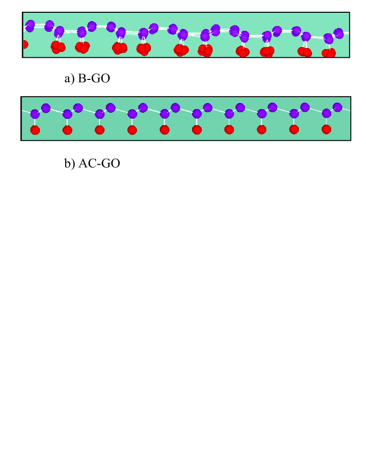
Figure 1 shows two side views of relaxed infinite (with periodic boundary condition applied in both directions of the plane) B-GO (a) and AC-GO (b) at =10 K using the MD method. In the AC-GO configuration, the hydrogens are relatively far from each other and the C-H bonds are mutually parallel and perpendicular to the plane, due to symmetry. In the B-GO the C-H bonds are attached to nearest neighbors C-C bond, which induces a corrugation in the hydrogen layer with C-H bonds that are not fully perpendicular to the plane, mainly because of the sp3 hybridization but also due to the stronger repulsion between te relatively close hydrogen atoms. Very similar configurations were obtained for GF, which are therefore not shown. It is important to note that such flat GOs (and one sided GFs) are energetically unfavorable chemPhysLett2012 . In this study we report on the structural transformations of these systems into stable, non-flat structures.
III.2 Ab-initio results: Graphone
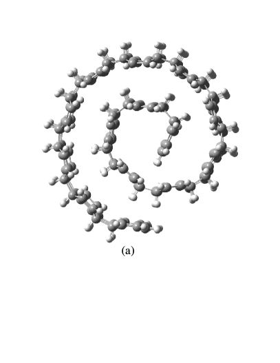
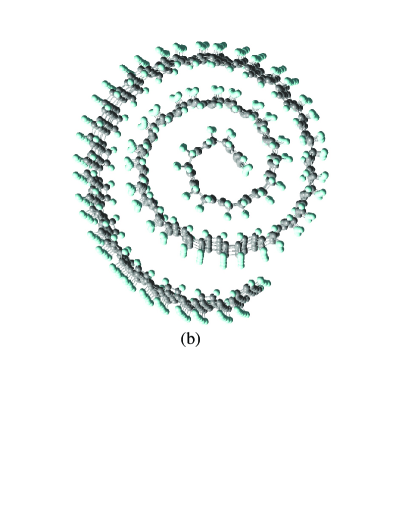
In Fig. 2(a) we show the optimized configuration of B-GO using ab-initio calculations with B3LYP/6-31G* and 504 atoms. Notice that the initial non-relaxed configuration was a flat sheet. In Fig. 2(b) an example of results from our semiempirical calculation using PM6 is shown.
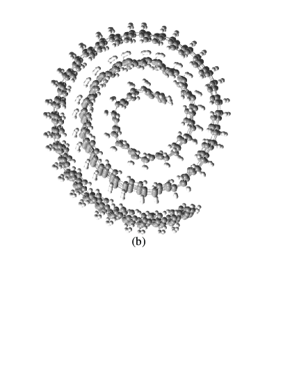
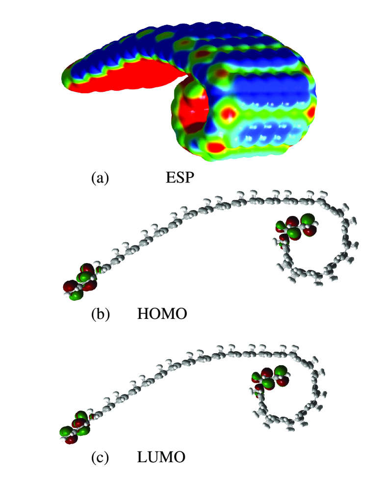
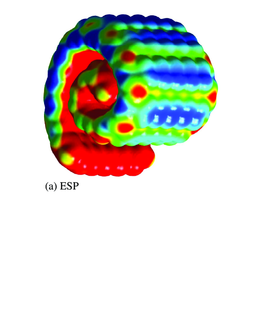
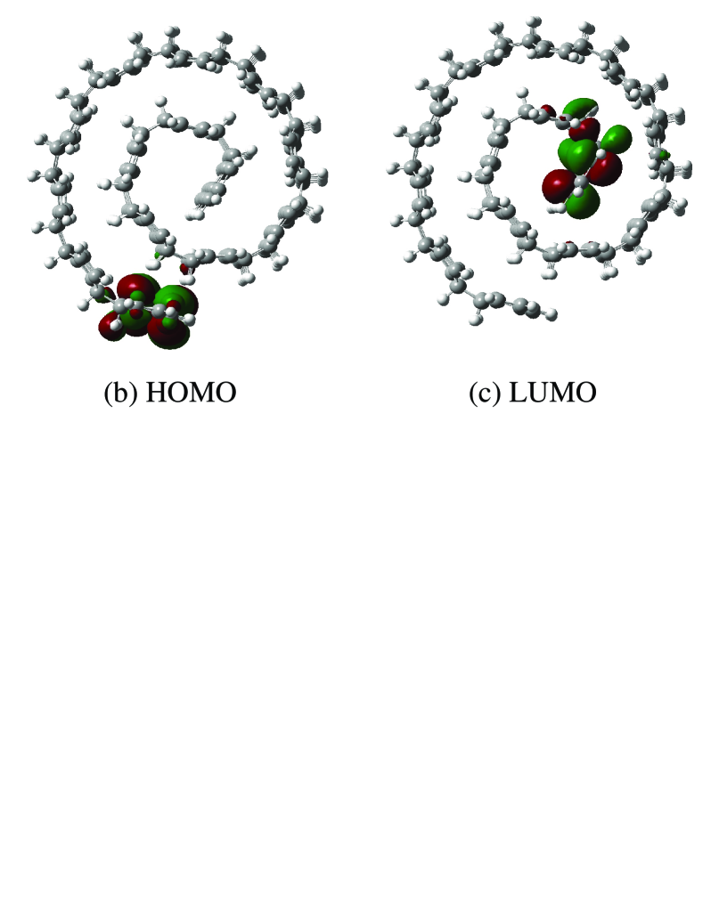
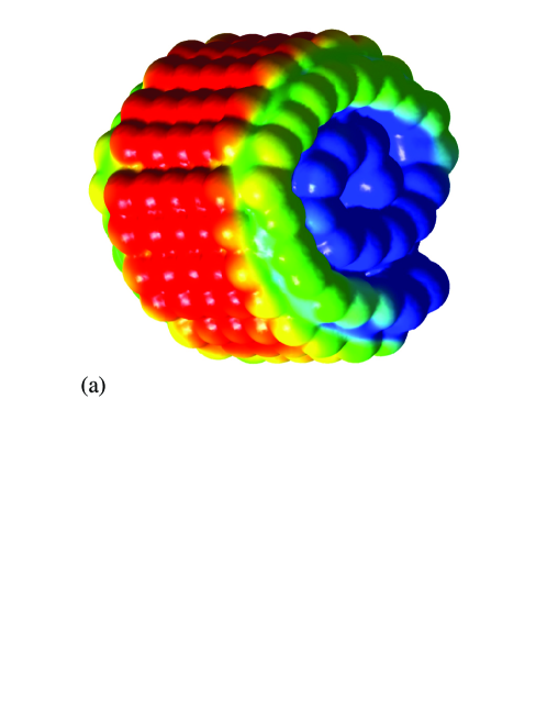
Figure 3(a) shows the electrostatic surface potential (ESP) of B-GO before the completion of the rolling process. The corresponding HOMO and LUMO are shown in Figs. 3(b,c) respectively. During rolling both HOMO and LUMO are localized at both ends simultaneously which is a consequence of the equivalent geometry. The ESP of completely rolled B-GO is shown in Fig. 4(a). The ESP indicates that the spiral structure has ionic characteristics, the red (blue) color indicating positively (negatively) charged regions, which stabilizes the spiral geometry even more.
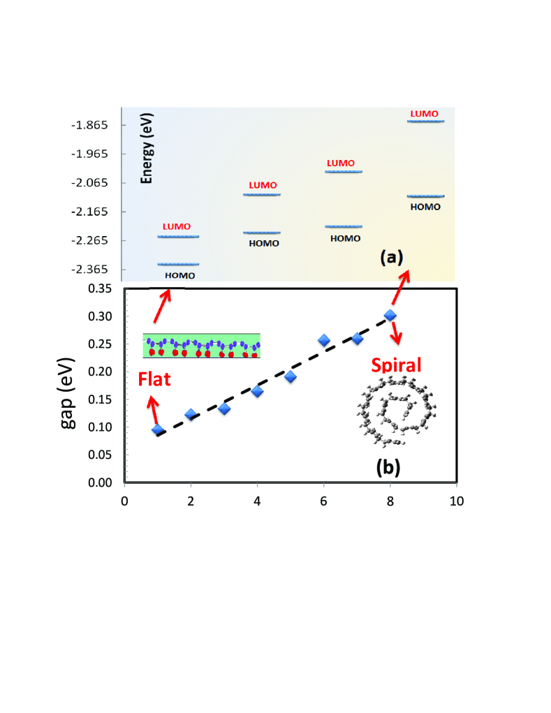
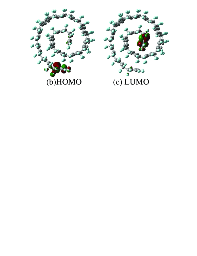
Surprisingly, after complete rolling, the HOMO and the LUMO are separated and both localized in only one end, as can be seen from Figs. 4(b-c), whereas before complete rolling they were localized in both ends simultaneously as already mentioned before (see Figs. 3(b,c)). These effects are related to the differences in electronegativity of the simulated atoms (HCF). Because of the difference in ESP at the two edges, the increment of the energy of the LUMO is larger than that of the HOMO, which results in a widening of the energy gap from 0.1 eV for the flat sheet to 0.3 eV for the spiral structure. This is shown more explicitly in Fig. 5, which reveals an almost linear increase of the gap during the evolution to a spiral.
III.3 Ab-initio results: One sided fluorinated graphene
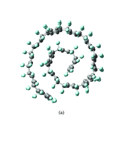
Very similar results are found for GFs. Figure 6(a) shows the spiral GFs obtained using B3LYP/6-31G*. The spiral GF formed using the PM6 method is shown in Fig. 6(b). These configurations are minimum energy configurations of B-GF. Similarly as for GO, the rolling is due to the one-sided, partial (here 50 %) coverage with F atoms and corresponding sp3 hybridization. The rolling process starts from free boundaries where there is no resistance against any torque.
III.4 Classical molecular dynamics simulation results: large size flakes
Using classical simulations, we first investigated the possibility to create hydrogenated CNT from one-sided hydrogenated AC-GO nano-ribbons, with periodic boundary condition along the zig-zag edge, having a specific length equal to =13.4 Å between the two free ends (in the flat geometry) . After relaxing the system at 10 K we found that always a (5,5) CNT is formed independent of the dimension of the box in the periodic direction (see movie in supplementary material suppl ). The used length for B-GO, i.e. =13.4 Å, agrees with the perimeter of a one-sided hydrogenated (5,5) CNT, i.e. with Å. The movie in Ref. suppl shows the time evolution for the rolling of an AC-GO which eventually forms a (5,5) hydrogenated CNT. This is consistent with previous results on the formation of CNT from partially hydrogenated graphene nanolett2007 . Note however that the formation of these nanotubes is constrained by the choice of the length of the ribbon, which has to be relatively small and should match with the size of an (n,n) tube.
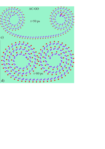
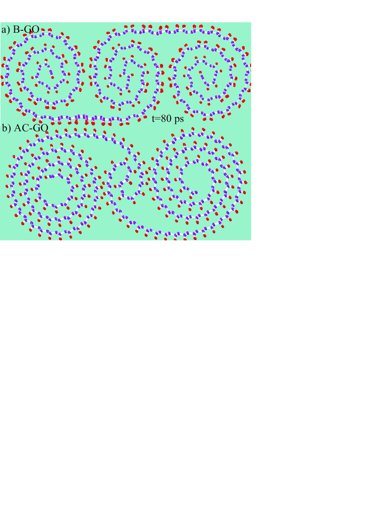
In the remainder of this section we show the rolling effect for much longer nano-ribbons, not leading to tube formation, using classical MD simulation. We used graphone nano-ribbons with free zig-zag edges and periodic boundary conditions in the direction parallel to these edges (lateral side) and found that the final, minimal energy configuration of both GO and GF is a spiral structure similar to what we found with DFT. Figures 8(a,b) show two snap shots from the rolled B-GO which are free at two longitudinal ends (here set to be zig-zag edges). Similar results are found for AC-GOs, see Figs. 8(c,d). As expected, the corrugations in B-GO are larger than in AC-GO. Thus, unrolling B-GO costs much more energy than AC-GO.
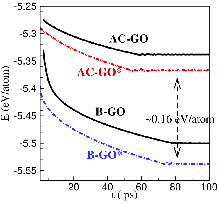
Figure 9 shows the variation of the total energy per atom as a function of the rolling process time for AC-GO, B-GO, AC-GO* and B-GO*. Clearly B-GO* is the most stable having the lowest energy. The energy gap between AC-GO (AC-GO*) and B-GO (B-GO*) is about 0.16 eV/atom. Furthermore it is seen that including the vdW energy term lowers slightly the energy by eV/atom due to the attractive van der Waals interaction. Notice that the ionic characteristic of the rolled structure cannot be reproduced by these classical simulation with AIREBO. Nonetheless, the classically found spiral structures are quite stable, which confirms that the main driving force for the rolling is the one-sided absorption and corresponding sp3 hybridization and not the ionic characteristics found in the DFT calculations.
In Fig. 10 rolled configurations of a system consisting of two connected GO parts that are hydrogenated at opposite sides are shown. Hydrogens at 0 (0) are bonded to the upper (lower) side of the sheet. Notice that the AC-GO and B-GO form different patterns of rolled GO with an extra rolled part in the middle. This hints to the interesting possibility to engineer the rolled shape of GO carefully by selectively hydrogenating parts of the initial graphene sheet.
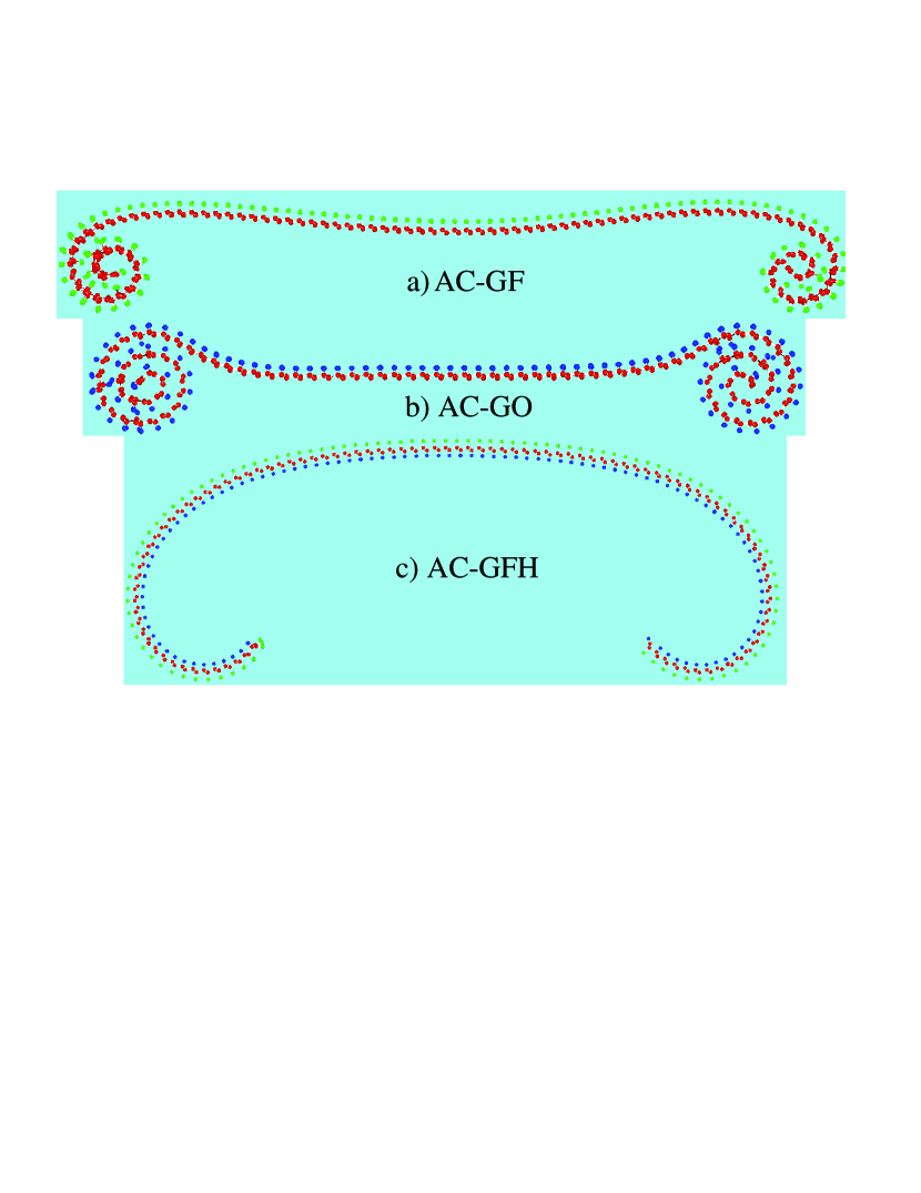
As an additional, final result of this section we present the rolling behavior of a system with one side covered by hydrogen and the another side covered by fluor, which we called ‘GFH’. Recently, by using ab-initio calculations, a negative formation energy was found for this system kast2010 . In Fig. 11 side views are shown for the rolled structure of AC-GF (a), AC-GO (b) and AC-GFH (c) after 25 ps of molecular dynamics simulations (red, green and blue balls are carbon, fluor and hydrogen, respectively). In all three cases we used the ReaxFF potential and the simulations were done at T=10 K, as before. It is clear from Fig. 11 that AC-GO (AC-GFH) has the largest (smallest) curvature, due to the fact that when one side is covered by hydrogen and the other side is covered by fluor, the driven force for rolling is partially balanced, but not completely as the fluor atoms are larger leading to a stronger intra-layer repulsion at the fluor side, so that the system still tends to roll, albeit with a much smaller curvature.
III.5 Temperature effects
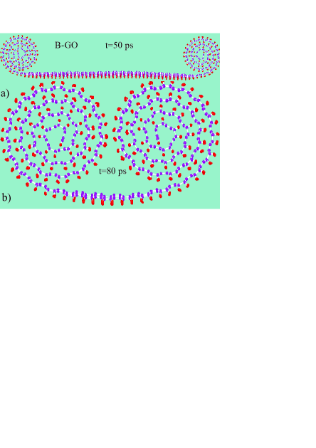
New structures have to be tested in terms of their stability against temperature. In order to study the temperature effects on the spiral B-GO, after obtaining it at 10 K (note that in principle spiral GO can also be formed at room temperature but we set =10 K in order to minimize thermal fluctuations and to find more rapidly the ground state spiral configurations) we raised the temperature up to 1000 K. Not so surprising in view of the significant gain in binding energy of 0.1 eV/atom ( 1200 K) for AC-GO and much more for B-GO (see Fig. 9) in their rolled states with respect to the flat configurations, the spiral GOs keep their configuration. Beyond 700 K the loops start to deform slightly. However, even at 1000 K the system is not un-zipped and the spiral configuration is conserved suppl at least within the here used MD simulation time of 1 ns. For T1000 K the system starts to separate into two different loops suppl . From these simulations we conclude that spiral GO should be rather stable at room temperature, facilitating its possible synthesis in future experiments. Two movies are provided in the supplementary materials suppl to show the rolling of B-GO at T=10 K and to show the stability of B-GO during the heating process up to T=1000 K. For GFs the spiral system is somewhat less stable. Close to 800 K the GFs start to un-roll and beyond this temperature they start to be fractured. Notice that the C-H bonds (C-F bonds) in GOs (GFs) are stable even after unrolling, thus no hydrogen release was observed when heating up the rolled sheets within our simulation time of 0.1 ns.
We also applied external uniaxial compression along the axis of the spiral structures in order to investigate the mechanical stability of these structures, which turned out to resists against the external pressure much better than graphene. Detailed mechanical properties of these new spiral hydrocarbons need further investigations.
IV Conclusions
Free boat like and arm-chair like one-sided hydrogenated/fluorinated
graphene (graphone/fluorographene) ribbons/flakes spontaneously
roll up to form spiral configurations which should be quite stable
at room temperature. The spiral structures exhibit strong mechanical
rigidity preventing them to unroll. The main driving force behind
the spiral formation is the energy relaxation associated with the
one-sided, asymmetric orientation of sp3 bonding. Further
modestly stabilizing factors are the van der Waals attractive
interaction between the stacked shells and (only in the DFT
calculations) the ionic interactions between the shells, which
appear to be polarized across the shell width. Boat-like
hydrogenated/fluorinated graphene yields more stable, spiral systems
than arm-chair like graphone. The graphene sheet where one
side is covered by hydrogen and the other side by fluor is unstable
and it also forms a rolled up structure, albeit with a smaller
curvature.. The highest occupied and lowest unoccupied orbital for
spiral GO and GF are localized at opposite ends of the system. The
energy gap increases when the
system evolves from the flat to the spiral shape.
Acknowledgments
We thank A.
Sadeghi, M. R. Ejtehadi and J. Amini for their useful comments. This
work is supported by the ESF EuroGRAPHENE project CONGRAN and the
Flemish Science Foundation (FWO-Vl).
References
- (1) A. K. Geim and K. S. Novoselov, Nature Mater. 6, 183 (2007); A. H. Castro Neto, F. Guinea, N. M. Peres, K. S. Novoselov, and A. K. Geim, Rev. Mod. Phys. 81, 109 (2009).
- (2) D. Pacile, J. C. Meyer, C. O. Girit, and A. Zettl, Appl. Phys. Lett. 92, 133107 (2008).
- (3) P. Vogt, P. D. Padova, C. Quaresima, J. Avila, E. Frantzeskakis, M. Carmen Asensio, A. Resta, B. Ealet, and G. Lay. Phys. Rev. Lett 108, 155501 (2012).
- (4) G-H. Lee, Y-J. Yu, C. Lee, C. Dean, K. L. Shepard, P. Kim, and J. Hone, Appl. Phys. Lett. 99, 243114 (2011).
- (5) K. S. Novoselov, A. K. Geim, S. V. Morozov, D. Jiang, Y. Zhang, S. V. Dubonos, I. V. Grigorieva, and A. A. Firsov, Science 306, 666 (2004).
- (6) M. H. F. Sluiter and Y. Kawazoe, Phys. Rev. B 68, 085410 (2003). J. O. Sofo, A. S. Chaudhari, and G. D. Barber, Phys. Rev. B 75, 153401 (2007).
- (7) R. Nair, W. Ren, R. Jalil, I. Riaz, V. Kravets, L. Britnell, P. Blake, F. Schedin, A. Mayorov, S. Yuan, M. Katsnelson, H. Cheng, W. Strupinski, L. Bulusheva, A. Okotrub, I. Grigorieva, A. Grigorenko, K. Novoselov, and A. K. Geim, small 6, 2877-2884 (2010).
- (8) M. Neek-Amal and F. M. Peeters, Phys. Rev. B 83, 235437 (2011); S. Costamagna, M. Neek-Amal, J. H. Los, and F. M. Peeters, Phys. Rev. B 86, 041408 (2012).
- (9) D. W. Boukhavalov, M. I. Katsnelson, and A. I. Lichtendtein, Phys. Rev. B 77, 035427 (2008).
- (10) D. C. Elias, R. R. Nair,T. M. G. Mohiuddin, S. V. Morozov, P. Blake, M. P. Halsall, A. C. Ferrari, D. W. Boukhvalov, M. I. Katsnelson, A. K. Geim, and K. S. Novoselov, Science 323, 610 (2009).
- (11) M. Z. S. Flores, P. A. S. Autreto, S. B. Legoas, and D. S. Galvao, Nanotechnology 20, 465704 (2009).
- (12) H. Sahin, C. Ataca, and S. Ciraci, Phys. Rev. B 81, 205417 (2010).
- (13) O. Leenaerts, H. Peelaers, A. D. Hernández-Nieves, B. Partoens, and F. M. Peeters, Phys. Rev. B 82, 195436 (2010).
- (14) A. D. Hernández-Nieves, B. Partoens, and F. M. Peeters, Phys. Rev. B 82, 165412 (2010).
- (15) Wen, X.D., L. Hand, V. Labet, T. Yang, R. Hoffmann, N.W. Ashcroft, A. Oganov, and A. Lyakhov, Proc. Natl. Acad. Sci. 108, 6833 (2011).
- (16) L. Hornekaer, Z. Sljivancanin, W. Xu, R. Otero, E. Rauls, I. Stensgaard, E. L gsgaard, B. Hammer, and F. Besenbacher, Phys. Rev. Lett. 96, 156104 (2006).
- (17) F. Dumont, F. Picaud, C. Ramseyer, C. Girardet, Y. Ferro, and A. Allouche, Phys. Rev. B 77, 233401 (2009).
- (18) R. Balog, B. J rgensen, L. Nilsson, M. Andersen, E. Rienks, M. Bianchi, M. Fanetti, E. L gsgaard, A. Baraldi, S. Lizzit, Z. Sljivancanin, F. Besenbacher, B. Hammer, T. G. Pedersen, P. Hofmann, and L. Hornek r, Nature Mater. 9, 315 (2010).
- (19) Duminda K. Samarakoon and Xiao-Qian Wang, ACS Nano 3, 4017 (2009).
- (20) J. Zhou, Q. Wang, Q. Sun, X. C. Chen, Y. Kawazoe, and P. Jena, Nano Lett. 9, 3867 (2009).
- (21) S. Lebegue, M. Klintenberg, O. Eriksson, and M. I. Katsnelson, Phys. Rev. B 79, 245117 (2009).
- (22) Konstantin N. Kudin and Gustavo E. Scuseria, and B. I. Yakobson, Phys. Rev. B 64, 235406 (2001).
- (23) Ji Zang, Minghuang Huang, and Feng Liu, Phys. Rev. Lett. 98, 146102 (2007).
- (24) V. V. Ivanovskaya, P. Wagner, A. Zobelli, I. Suarez-Martinez, A. Yaya, and C. P. Ewels, Carbon Nanostructures, 25, 75 (2012).
- (25) D. Yu, and F. Liu, Nano Lett. 7, 3046 (2007).
- (26) O. O. Kit, T. Tallinen, L. Mahadevan, J. Timonen, and P. Koskinen, Phys. Rev. B 85, 085428 (2012).
- (27) D. V. Kosynkin, A. L. Higginbotham, A. Sinitskii, J. R. Lomeda, A. Dimiev, B. K. Prince, and J.M. Tour, Nature (London) 458, 872 (2009).
- (28) L. Jiao, L. Zhang, X. Wang, G. Diankov, and H. Dai, Nature (London) 458, 877 (2009).
- (29) Juan J. Vilatela and Dominik Eder, ChemSusChem 5, 456 (2012).
- (30) F. Alvarez-Ram rez, J. A. Toledo-Antonio, C. Angeles-Chavez, J. H. Guerrero-Abreo, and E. Lopez-Salinas, J. Phys. Chem. C 115, 11442 (2011).
- (31) G. Shen, B. Liang, X. Wang, P-C. Chen, and C. Zhou, ACS Nano 5, 2155 (2011).
- (32) K. Fukui, T. Yonezawa, and H. Shingu, J. Chem Phys 20, 722 (1952).
- (33) M. J. Frisch, et al (GAUSSIAN 1998).
- (34)
- (35) S. J. Stuart, A. B. Tutein, and J. A. Harrison, J. Chem. Phys 112, 6472 (2000).
- (36) A. C. T. van Duin, S. Dasgupta, F. Lorant, and W. A. Goddard, J. Phy. Chem. A 105, 9396 (2001).
- (37) D. W. Brenner, O. A. Shenderova, J. A. Harrison, S. J. Stuart, B. Ni, and S. B. Sinnot, J. Phys.: Condens. Matter 14, 783 (2002).
- (38) Z. Slijvancanin, R. Balog, and L. Hornekær, Chem. Phys. Lett 541, 70 (2012).
- (39) Four movies of the rolled GO, GF, an the temperature effect and the formation of CNT are provided in the Supplementary Material.
- (40) M. Klintenberg, S. Lebégue, M. I. Katsnelson, and O. Eriksson, Phys. Rev. B 81, 085433 (2010).