Thermal properties of fluorinated graphene
Abstract
Large scale atomistic simulations using the reactive force field approach (ReaxFF) are implemented to investigate the thermomechanical properties of fluorinated graphene (FG). A new set of parameters for the reactive force field potential (ReaxFF) optimized to reproduce key quantum mechanical properties of relevant carbon-fluor cluster systems are presented. Molecular dynamics (MD) simulations are used to investigate the thermal rippling behavior of FG and its mechanical properties and compare them with graphene (GE), graphane (GA) and a sheet of BN. The mean square value of the height fluctuations and the height-height correlation function for different system sizes and temperatures show that FG is an un-rippled system in contrast to the thermal rippling behavior of graphene (GE). The effective Young’s modulus of a flake of fluorinated graphene is obtained to be 273 N/m and 250 N/m for a flake of FG under uniaxial strain along arm-chair and zig-zag direction, respectively.
pacs:
72.80.Vp, 68.65.Pq, 73.22.PrI Introduction
The fascinating properties of single layer graphene (GE) have triggered a broad interest in the solid state physics community novo ; Geim ; Berger ; Katsnelson ; Sahin . Despite its high electron mobility castro-neto , the zero band gap defies its employment in nano transistors where it is desirable to have a large on-off ratio between conducting and non-conducting states. A band gap can be induced by the addition of adatoms, which changes locally the hybridization of the carbon (C) atoms, but also modifies the electron mean free-path affecting the electron transport properties. Hydrogen (H) and fluor (F) are two well tested candidates elias ; Nair ; robinson ; zboril that leads to a large band gap opening. Graphane (GA, hydrogenated graphene) and fluorographene (FG) have been studied both experimentally and theoretically Cheng ; Withers ; leenaers1 ; samarakoon to engineer the band gap.
When H or F atoms are attached to the C atoms of GE, the bonds transit from an sp2 to an sp3 hybridization, which turns the conjugated graphitic C-C bonds into single C-C bonds. In the fully covered cases both GA and FG are insulating materials elias ; Nair and the structure changes locally the planar shape of GE into an angstrom scale out-of-plane buckled shaped membrane PRB77 known as chair configuration sluiter ; sofo .
From its potential applications in nanotechnology, FG is a more favourable material than GA since the C-F bonds are energetically more stable than the C-H bonds leenaers1 ; PRB77 ; sofo ; Sahin1 . Fluorographene has a very large temperature-dependent resistance and when the fluor content is increased it induces large changes in the electron transport freddie1 . As in GE, it is expected that temperature also affects strongly the lattice structure and the mechanical properties of FG.
According to the Mermin-Wagner theorem, mermin , thermal excited ripples in two dimensional-like materials (GE, bilayer GE, GA and FG) has to play an important role in the stability of the membrane. While in GE and bilayer GE the corrugations are well described within the theory of two dimensional continuous membranes bilayer ; 3 , for GA instead, we recently found that the angstrom scale buckling of the carbon layer of GA prevents the formation of intrinsic long wavelength thermal ripples for temperatures up to at least 900 seba2012 .
Since the C atom has a higher (lower) electronegativity than H (F), it will take (give) away charge from the H (F) atom and consequently transforms the resulting C-H and C-F covalent bonds into sp3 bonds. Therefore, it is expected that similar rippling effects as in GA will occur in FG although the C-F bonds are somewhat stronger than the C-H bonds. The latter is due to the larger amount of charge that is shifted from C to F as compared to the one from H to C leenaers1 . However in order to simulate large scale FG samples an appropriate force field is needed which describes the true chemical bond in C-F. Indeed, the absent of such a suitable interatomic potential for C-F restricted most of the recent studies to ab-initio calculations of their electronic properties using a small computational unit cell.
ReaxFF potential serves to describe both bond and non-bond interactions in solids. Recently, such potentials were parameterized and were well tested for different kind of structures, e.g. hydrocarbons van , carbon allotropes Mueller , etc. In this study we present a new set of parameters for ReaxFF, appropriate for structures with C-F bonds. Using molecular dynamics (MD) simulations over large scale samples we study the thermal corrugations of FG and compare the results with those found for GA, GE and BN. We show that fully covered FG follows the same trend as GA and does not develop long-wavelength ripples or significant corrugation. The bending rigidity of FG is found to be larger than the one of GE, GA and BN. Furthermore, turns out to be temperature independent. Our results indicate that long-wavelength ripples are instead present in partial covered FG samples with a larger amplitude as compared to GA.
The paper is organized as follows. In Sec. II, we introduce a new set of parameters for the ReaxFF potential of the C-F covalent bond. Then, in Sec. III using the introduced parameters, we analyze the thermal rippling behavior. Here, we consider both fully and partially covered graphene sheets by F atoms. All the results are compared with those previously found for graphane. We also estimate the effective Young’s modulus of FG flakes. We conclude the paper in Sec. IV.
II ReaxFF potential for Fluorographene
ReaxFF van is a general bond-order dependent potential that uses a relationship between bond distance and bond order on the one hand and a relationship between bond order and bond energy on the other hand to describe bond formation and dissociation. Many body interactions such as the valence angle and torsional interactions are formulated as function of bond order so that their energy contributions vanish smoothly upon bond dissociation. Non bonded interactions, namely Coulomb and van der Waals interactions, are calculated between every pair of atoms irrespective of their connectivity. Excessively close range interactions are avoided by shielding. ReaxFF uses the geometry dependent charge calculation scheme (EEM scheme) of Mortier et al mortier . The system energy in ReaxFF consists of a sum of terms:
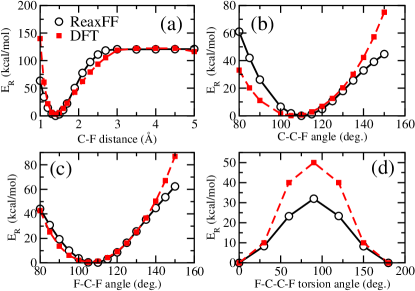
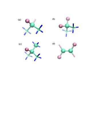
A detailed description of each of these terms and their functional forms can be found in the original work van . The reactive force field for C/F containing systems was developed by parameterizing the potential against DFT data obtained at the B3LYP/6-31g** level of theory (which is implemented in Schrodinger S11 which is an electronic structure packages) for various quantities such as fluorine and carbon atom charges in H3CCFCH3, CF and CC bond lengths in H3CCFCH3 and H3CCF(CH3)CH3, FF bond length in the F2 molecule, potential energy curve for C-F bond dissociation in H3CCFCH3, F-C-F angle bending in H3CCFCH3, C-C-F angle bending in H3CCFCH3 and F-C-C-F dihedral twisting in F2CCF2 along with various chemical reactions involving fluoroalkanes and fluoroalkenes. The results of the force field training are presented in Figs. 1(a)-(d) and in Table III.1. Fig. 2 depicts the geometrical quantities relevant to Figs. 1(a)-(d). It can be seen from Table III.1 that ReaxFF reproduces closely the DFT based equilibrium geometries for various compounds. ReaxFF predicts F2 dissociation energy of 36.6 kcal/mol, in very good agreement with the DFT value of 37 kcal/mol. Fig. 1(a) shows that ReaxFF based potential energy curve for the C-F bond dissociation in H3CCFCH3 closely follows the DFT based potential energy curve. ReaxFF is able to predict very precisely the equilibrium C-F bond length (see Table III.1) and the C-F bond dissociation energy. Similarly the force field can closely reproduce the DFT based potential energy curve and the equilibrium geometry (see Table III.1) for C-C-F angle bending and the C-F-C angle bending as shown in Figs. 1(b)-(c). Figure 1(d) shows the variation of the potential energy upon F-C-C-F dihedral angle twisting. Though ReaxFF predicts the correct trend, the torsional rotation barrier in ReaxFF is around 18 kcal/mol lower than that predicted by DFT. Overall, the ReaxFF force field for C/F systems can closely reproduce the DFT based energies and geometries for a number of molecules and reactions. This force field will now be employed in large scale fully reactive molecular dynamics simulation of C/F containing systems.
In the next section we study the thermal structural fluctuations and mechanical properties of a single layer of FG using large scale atomistic simulations employing the presented ReaxFF parameters. These parameters were implemented in the large-scale atomic/molecular massively parallel simulator package LAMMPS lammps ; Plimpton .
| DFT | ReaxFF | |
|---|---|---|
| F2 bond length | 1.43Å | 1.4012Å |
| C-F bond length in H3C-CF2-CH3 | 1.3841Å | 1.4057Å |
| C-F bond length in H3C-CF(CH3)-CH3 | 1.3841Å | 1.4158Å |
| Non-bonding C-F distance in CF2 dimer | 2.00 Å | 2.4471Å |
| F-C-F angle in H3C-CF2-CH3 | 105.65o | 107.2197 o |
| C-C-F angle in H3C-CF(CH3)-CH3 | 106.2 o | 109.9625 o |
III Results
III.1 Thermal rippling behavior of FG
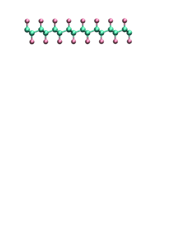
In order to study the rippling behavior of FG we considered a square shaped computational unit cell of FG with both armchair and zigzag edges in the and directions. Partial fluor contents of 10, 50, 70, 90 and the fully covered 100 case (with a total number of atoms) were studied. In our simulation we employed the NPT ensemble with =0 using the Nosé-Hoover thermostat and varied the temperature from 10 K to 900 K. Figure 3 shows the obtained buckled shape of fully fluorinated sample after relaxation which is in agreement with recent DFT results leenaers1 .
One would expect that the thermal excited ripples in FG can be described by membrane theory for a 2D continuous membrane Nelson . This theory, described in a series of related works seba2012 ; GE2d ; seba1 ; roldan , is supposed to be universal and independent of the atomic scale details of the membrane. The main predictions of this theory are as follows. Let be the out-of plane displacement of a given atom of a sheet, then the Fourier transform of the height-height correlation function is in the harmonic approximation given by
| (1) |
where is the wave-vector, is the number of atoms, is the surface area per atom, is the bending rigidity of the membrane, and is the Boltzmann constant.
In the large wavelength limit, anharmonic couplings between bending and stretching modes are important resulting in a renormalization of the -dependent behavior
| (2) |
where is an universal scaling exponent which is about ledousal ; LCBOPII ; fas1 .
In order to compare our results for FG with other two dimensional materials, we used a modified Tersoff potential (which is an ordinary defined potential in the LAMMPS package Plimpton ) according to the parameters proposed by Sevik et al for the h-BN sheet [Sevik, ]. To simulate GE and GA we have used the AIREBO potential AIREBO which is suitable for simulating hydrocarbons.
Recently, we found that in GA, acquires a strong renormalization for small wave-vectors and the layer remains almost flat even for temperatures as high as 900 K seba2012 . Here we will analyze the thermal rippling behavior of FG and compare it with GA. A comparison with GE and BN single layers which behave as 2D membranes GE2d ; seba3 will also be presented. for FG was calculated following the steps described in our previous work seba2012 .
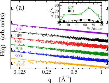
Starting from a pure GE sheet, the variation of the height-height correlation function at room temperature for different partial fluor contents is shown in Fig. 4 (a). The curves were shifted for a better comparison. We found that while for 10 to 90 coverage, follows Eq. (2) up to small values which is similar to the case of GE seba1 . But, for fully FG at , deviates from the harmonic law (solid line) and approaches roughly a constant value similar to was previously found for GA seba2012 . In the inset of Fig. 4(a) we show the square average of the out-of-plane fluctuations at 300 K. Notice that the out of plane fluctuations for partially covered samples are considerably larger for FG than for GA. The temperature dependence of for fully fluorinated graphene is shown in Fig. 4(b). Irrespective of temperature, the short wave-length limit of tends always approximately to a constant value. The characteristic -value where deviates from the harmonic approximation result decreases with increasing temperature.

The renormalization of for long wavelengths indicates the suppression of large out-of-plane height fluctuations. In Fig. 5(a) we compare the behavior of against temperature for GE, BN (panel (a.1)), FG and GA (panel (a.2)). Notice that increases from up to in BN and from up to in GE when temperature is varied from up to 900 K. Due to the absence of long wave-length ripples, remains approximately constant for GA and FG, and the variations are smaller than those for BN and GE, over the same temperature range. The temperature dependence of the bending rigidity , computed from the harmonic part of H(q) is shown in Fig. 4(b). Note that the larger magnitude for GA and FG is a consequence of the smaller corrugations present in these materials. We also find the opposite temperature dependence for BN and GE when compared with GA and FG. In this sense GE and BN behave anomalously. The corresponding bending rigidity and at room temperature for GE, GA and FG are listed in Table II.

| AIREBO | ReaxFF | |||||
|---|---|---|---|---|---|---|
| (Å2) | (Å2) | |||||
| GE | 1.165 | 1.307 | 1.16 | 0.627 | ||
| GA | 10.19 | 0.070 | 7.26 | 0.074 | ||
| GF | – | – | 5.07 | 0.073 |
Comparison of AIREBO and ReaxFF for the bending rigidity and for GE, GA and FG at 300 K. Density functional calculations for band structure of FG (and GA) APLHar shows that the acoustic out-of-plane modes (ZA) in FG (and GA) are different from that of GE. The most important difference from GE is the decoupled optical and acoustic bands in FG and GA close to the point. The light H atom contributes to the highest phonon frequencies which is not the case for F atoms. It is also seen that the ZA modes close to the point for FG (and GA) are not well fitted by a quadratic function in contrast to the GE case. This is clear indication of anharmonicity. In summary, the atomistic details of the structure of FG is more complicated and therefore more details of this structure should be included in any continuum theory. Before ending this section, note that as we discussed in our previous work seba2012 , the scaling with the system size present in GE is no longer valid for FG and GA ( in FG and GA is almost constant irrespective to the system size). The lower wavelengths () adopted for the calculation of are equal to and and represent the ’computational’ cut-offs of possible large wavelength ripples where and are the dimension of the system. Notice that deviation from the harmonic behavior takes place at larger value of and hence this effect can not be a finite size effect and is instead an intrinsic phenomenon of the material.
III.2 Effective Young’s modulus
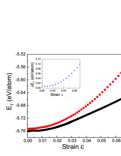
In order to study the mechanical stiffness we consider an FG flake with dimension nm2. Before the stretching process, the sample is equilibrated for 5 ps (i.e. 50,000 time steps). Stretching direction is always along and the uniaxial strain is applied within the NPT ensemble NanoTech where the pressure is slowly increased, i.e. 2 GPas/ps. In this section the lateral edges (in the direction) were taken as the arm-chair direction having both free (FBC) and periodic boundary conditions (PBC). We kept temperature fixed at T=10 K. The total strain energy per atom of the strained flake can be written as a function of the imposed strain ()
| (3) |
where is the energy of the infinite planar undeformed flake, is the excess edge energy, and is Young’s modulus () of the flake. For nano-ribbons with no lateral edges we have (assuming that the longitudinal edges which are fixed make no contribution). This is due to the fact that free edges increase the energy due to buckling and bond-order changes Lu2010 . Recently Lu et al used the Brenner potential brenner in molecular dynamics simulations and studied the excess edge energy of graphene nano-ribbons as a function of width and chirality Lu2010 . Our systems are different from those of Ref. Lu2010 . In contrast to Ref. Lu2010 we are not interested in effects due to the edge energy effect and the size dependence. We rewrite Eq. (3) in the following as an effective Young’s modulus which qualitatively gives a good description of the mechanical stiffness of all the examined 2D materials. Nevertheless our results are in qualitative agreement with those reported by Lu at al, i.e. increasing of total energy for the FBC case as compared to a nano-ribbon. Assuming a quadratic relation for valid for small , the simplest method to estimate Young’s modulus is by fitting the quadratic function to the total energy (per area):
| (4) |
where is the effective Young’s modulus of the system. Using aforementioned fitting process we found respectively for a flake with arm-chair and zig-zag FG, to be 273 N/m and 250 N/m. Notice that the experimental result is 100 N/m for not perfect FG Nair while the DFT result is 250 N/m Sahin1 . The latter disagreement between theory and experiment may be explained due to the fact that in experimental samples the fluor-to-carbon ratio is larger than unity, i.e. 1.1 Nair , because of the presence of defects. Such defects become active regions which can adsorb the free F (and even H) atoms. Therefore, in the defected parts more F atoms will be found which is responsible for a F/C ratio larger than one. In order to understand the effect of the different boundary conditions, we depict in Fig. 6 the variation of per atom with for flakes with both FBC (dashed lines) and PBC, i.e. nano-ribbon (solid lines). It is seen that for flakes with FBC the free edges result in an increase of the energy. The inset shows the difference between two curves, i.e. which is positive. Because the free boundaries have many dangling bonds which are not saturated by F atoms it results in extra energy. This can also occur in other systems, e.g. graphene PRL2008 . Notice that for the studied low temperature here, i.e. T=10 K we do not expect that bond reconstruction at the edges is important. Notice that even by saturating all the bonds by F, still the change in the bond order term in ReaxFF (due to different chemical environment of the boundary atoms) results in higher energy as compared to PBC. Furthermore, both FBC and PBC results exhibit a quadratic behavior which is an indication of the harmonic regime for the applied uniaxial stain. As is clear from the inset of Fig. 6, the difference between the two curves is increasing with applied strain. This is due to the deviation from equilibrium for the C-F bonds, C-C-F (F-C-F) bond angles, and the dihedral angles (F-C-C-F torsion angle) of the free edge atoms. The larger the strain (and the larger the length of ribbon), the larger the deviation from equilibrium for the bonds and the angles. In the PBC case there is no such edge effect but nevertheless because of the fixing of the two longitudinal ends (the edges which are under uniaxial stress) the energy variation of the PBC system should be different from that of an infinite FG which is periodic in both directions while it is under tension from the arm-chair direction. The fixed longitudinal ends do not have any effect in our results because both FBC and PBC have the same contributions.
IV Conclusions
We provided a new set of parameters for the ReaxFF potential for the C-F covalent bond and tested it on various molecules. Subsequently, molecular dynamics simulations were used to investigate the thermal rippling behavior and the mechanical response of fluorographene (FG) under uniaxial stress. The obtained results are compared with those for graphene (GE), graphane (GA) and hexagonal boron nitride sheet (BN). We found that fluorographene remains a flat sheet similar to graphane even at high temperature, i.e. up to 900 K. The bending rigidity of FG is found to be independent of temperature and its Young’s modulus is in good agreement with experiment. Acknowledgments. This work is supported by the ESF-Eurographene project CONGRAN, the Flemish Science Foundation (FWO-Vl) and the Methusalem Foundation of the Flemish Government. SGS and ACTvD acknowledge support by the Air Force Office of Scientific Research (AFOSR) under Grant FA9550-10-1-0563.
References
- (1) K. S. Novoselov, A. K. Geim, S. V. Morozov, D. Jiang, Y. Zhang, S. V. Dubonos, I. V. Grigorieva, and A. A. Firsov, Science 306, 666 (2004).
- (2) A. K. Geim and K. S. Novoselov, Nat. Mater. 6, 183 (2007).
- (3) C. Berger, Z. Song, T. Li, A. Y. Ogbazghi, R. Feng, Z. Dai, A. N. Marchenkov, E. H. Conrad, P. N. First, and W. A. de Heer, Science 312, 1191 (2006).
- (4) M. I. Katsnelson, K. S. Novoselov, and A. K. Geim, Nat. Phys. 2, 620 (2006).
- (5) H. Şahin, R. T. Senger, and S. Ciraci, J. Appl. Phys. 108, 074301 (2010).
- (6) A. H. Castro Neto, F. Guinea, N. M. R. Peres, K. S. Novoselov, and A. K. Geim, Rev. Mod. Phys. 81, 109 (2009).
- (7) D. C. Elias, R. R. Nair,T. M. G. Mohiuddin, S. V. Morozov, P. Blake, M. P. Halsall, A. C. Ferrari, D. W. Boukhvalov, M. I. Katsnelson, A. K. Geim, and K. S. Novoselov, Science 323, 610 (2009).
- (8) R. R. Nair, W. Ren, R. Jalil, I. Riaz, V. G. Kravets, L. Britnell, P. Blake, F. Schedin, A. S. Mayorov, S. Yuan, M. I. Katsnelson, H. M. Cheng, W. Strupinski, L. G. Bulusheva, A. V. Okotrub, I. V. Grigorieva, A. N. Grigorenko, K. S. Novoselov, and A. K. Geim, Small 6, 2877 (2010).
- (9) J. T. Robinson, J. S. Burgess, C. E. Junkermeier, S. C. Badescu, T. L. Reinecke, F. K. Perkins, M. K. Zalautdniov, J. W. Baldwin, J. C. Culbertson, P. E. Sheehan, and E. S. Snow, Nano Lett. 10, 3001 (2010).
- (10) R. Zboril, F. Karlicky, A. B. Bourlinos, T. A. Steriotis, A. K. Stubos, V. Georgakilas, K. Safarova, D. Jancik, C. Trapalis, and M. Otyepka, Small 6, 2885 (2010).
- (11) S. H. Cheng, K. Zou, F. Okino, H. R. Gutierrez, A. Gupta, N. Shen, P.C. Eklund, J. O. Sofo, and J. Zhu, Phys. Rev. B 81, 205435 (2010).
- (12) F. Withers, M. Dubois, and A. K. Savchenko, Phys. Rev. B 82, 073403(2010).
- (13) O. Leenaerts, H. Peelaers, A. D. Hernández-Nieves, B. Partoens, and F. M. Peeters, Phys. Rev. B 82, 195436 (2010).
- (14) D. K. Samarakoon, Z. Chen, C. Nicolas, and X. Q. Wang, Small 7, 965 (2011).
- (15) D. W. Boukhavalov, M. I. Katsnelson, and A. I. Lichtenstein, Phys. Rev. B 77, 035427 (2008).
- (16) M. H. F. Sluiter and Y. Kawazoe, Phys. Rev. B 68, 085410 (2003).
- (17) J. O. Sofo, A. S. Chaudhari, and G. D. Barber, Phys. Rev. B 75, 153401 (2007).
- (18) H. Şahin, M. Topsakal, and S. Ciraci, Phys. Rev. B 83, 115432 (2011).
- (19) F. Withers, S. Russo, M. Dubois, and M. F. Craciun, Nanoscale Res. Lett. 6, 526 (2011).
- (20) N. D. Mermin and H. Wagner, Phys. Rev. Lett. 17, 1133 (1996).
- (21) K. V. Zakharchenko, J. H. Los, M. I. Katsnelson, and A. Fasolino, Phys. Rev. B 81, 235439 (2010).
- (22) J. C. Meyer, A. K. Geim, M. I. Katsnelson, K. S. Novoselov, T. J. Booth, and S. Roth, Nature (London) 446, 60 (2007). D. A. Kirilenko, A. T. Dideykin, and G. Van Tendeloo, Phys. Rev. B 84, 235417 (2011).
- (23) S. Costamagna, M. Neek-Amal, J. H. Los, and F. M. Peeters, Phys. Rev. B 86, 041408 (2012).
- (24) A. C. T. van Duin, S. Dasgupta, F. Lorant, and W. A. Goddard, J. Phys. Chem. A 105, 9396 (2001).
- (25) J. E. Mueller, A. C. T. van Duin, and W. A. Goddard III, J. Phys. Chem. C 114, 4939 (2010).
- (26) W. J. Mortier, S. K. Ghosh, and S. Shankar, J. Am. Chem. Soc. 108, 4315 (1986).
- (27) Jaguar, version 7.8, Schrodinger, (LLC, New York, NY, 2011).
- (28)
- (29) S. J. Plimpton, J. Comp. Phys. 117, 1 (1995).
- (30) D. Nelson, T. Piran, and S. Weinberg, Statistical Mechanics of Membrane and Surface (Word Scientific, Singapore, 2004).
- (31) A. Fasolino, J. H. Los, and M. I. Katsnelson, Nat. Mater. 6, 858 (2007).
- (32) S. Costamagna and A. Dobry, Phys. Rev. B 83, 233401 (2011).
- (33) R. Roldán, A. Fasolino, K. V. Zakharchenko, and M. I. Katsnelson, Phys. Rev. B 83, 174104 (2011).
- (34) P. Le Doussal and L. Radzihovsky, Phys. Rev. Lett. 69, 1209 (1992).
- (35) J. H. Los, L. M. Ghiringhelli, E. J. Meijer, and A. Fasolino, Phys. Rev. B 72, 214102 (2005).
- (36) J. H. Los, M. I. Katsnelson, O. V. Yazyev, K. V. Zakharchenko, and A. Fasolino, Phys. Rev. B 80, 121405 (2009).
- (37) C. Sevik, A. Kinaci, J. B. Haskins, and T. Çağin, Phys. Rev. B 84, 085409 (2011).
- (38) S. J. Stuart, A. B. Tutein, and J. A. Harrison, J. Chem. Phys. 112, 6472 (2000).
- (39) S. K. Singh, M. Neek-Amal, S. Costamagna, and F. M. Peeters, Submitted to Phys. Rev. B (2012).
- (40) H. Peelaers, A. D. Hernandez-Nieves, O. Leenaerts, B. Partoens, and F. M. Peeters, Appl. Phys. Lett. 98, 051914 (2011).
- (41) Y. Zheng, N. Wei, Z. Fan, L. Xu, and Z. Huang, Nanotechnology 22, 405701 (2011).
- (42) Q. Lu, W. Gao, and R. Huang, Phys. Rev. B 81, 155410 (2010); ibid J. Phys.: Condens. Matter 19, 054006 (2011).
- (43) D. W. Brenner, O. A. Shenderova, J. A. Harrison, S. J. Stuart, B. Ni, and S. B. Sinnott, J. Phys.: Condens. Matter 14, 783 (2002).
- (44) P. Koskinen, S. Malola, and Häkkinen, Phys. Rev. Lett. 101, 115502 (2008).