Pure Coordination using the Coordinator–Configurator Pattern
Abstract
This work-in-progress paper reports on our efforts to improve different aspects of coordination in complex, component-based robotic systems. Coordination is a system level aspect concerned with commanding, configuring and monitoring functional computations such that the system as a whole behaves as desired. To that end a variety of models such as Petri-nets or Finite State Machines may be utilized. These models specify actions to be executed, such as invoking operations or configuring components to achieve a certain goal.
This traditional approach has several disadvantages related to loss of reusability of coordination models due to coupling with platform-specific functionality, non-deterministic temporal behavior and limited robustness as a result of executing platform operations within the context of the coordinator.
To avoid these shortcomings, we propose to split this “rich” coordinator into a Pure Coordinator and a Configurator. Although the coordinator remains in charge of commanding and reacting, the execution of actions is deferred to the Configurator. This pattern, called Coordinator–Configurator, is implemented as a novel Configurator domain specific language that can be used together with any model of coordination. We illustrate the approach by refactoring an existing application that realizes a safe haptic coupling of two youBot mobile manipulators.
I Introduction
The context of this work (and hence also for the described pattern) is complex, component-based robotics and machine tool systems operating under real-time constraints. For building such systems, an increasingly acknowledged best practice is to separate the concerns of Coordination, Computation, Configuration and Communication [11, 9].
Computation defines the basic, functional building blocks from which a system is constructed. Communication defines how and with whom the individual elements of a system communicate. Configuration defines the properties of a system . Lastly, Coordination is concerned with supervising and monitoring the computations in way that the system as a whole behaves as intended.
Classical coordination models that have been used in robotics are Petri-Nets [12], Finite State Machines (FSM) [2] and Statecharts [7, 6]. These models are used to define when certain behaviors shall be executed. For instance UML FSM [8] allows execution of a behavior upon entering or exiting a state. The exact actions available depend on the primitives of the underlying framework, and may include invoking operations or modifying the configuration of a component.
This traditional approach has three major disadvantages. Firstly, reusability of coordination models is reduced because the model is polluted with platform specific information. In other words, reusing the same model on a different robot or software framework requires intrusive refactoring to replace the platform specific operations used in coordinator. Secondly, the blocking invocation of operations on functional computations can severely degrade the determinism of the Coordinator. Lastly, Coordinator robustness is reduced since an invocation might block indefinitely or crash, either of which may effectively render the coordinator inoperative.
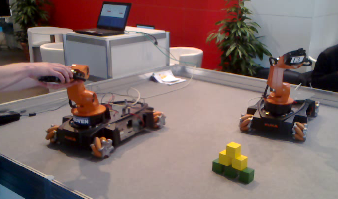
This paper proposes the Coordinator–Configurator pattern to overcome these challenges. The Configurator has been implemented as an Lua [4] based internal domain specific language (DSL) for the Orocos Real Time Toolkit (RTT) framework [13] and is to be complemented by a Coordination model such as rFSM [5]. We have applied a preliminary version to a moderately complex application111This demo was shown at the Automatica trade fair 2012 in Munich. consisting of a haptic, force-controlled coupling of two KUKA youBots in which multiple constraints are monitored and their violation is reacted to by the coordinator.
I-A Related work
From a object oriented software engineering perspective, the classical command design pattern [3] comes close to our suggestion by permitting a client to request an invoker to execute a given command on a recipient.
The ROS [10] framework provides the actionlib library as a standardized protocol to define commands that can be executed, monitored, aborted, etc. Hence it is not a form of Configurator, but rather a mechanism that could be used to implement one.
Since this work is concerned with constructing modular subsystems, the work of the Ptolemy project [1] is relevant, although that is more focused on composition of heterogeneous systems.
I-B Outline
The remainder of this article is structured as follows. The following section describes the Coordinator–Configurator pattern in detail and introduces the configuration DSL that underlies the Configurator. Section V critically examines the solution and discusses further potential uses of the DSL. Section VI concludes and describes future work.
II Approach
To overcome the described shortcomings, we propose to split the “rich” coordinator into a Pure Coordinator and a Configurator, named the Coordinator–Configurator pattern. Although the coordinator remains in charge of commanding and monitoring, the execution of actions is deferred to the Configurator. The Configurator is realized as a software entity (typically a component), that is configured with a set of configurations. Each configuration describes one possible state of the system and is identified by a unique name. Furthermore, a Configurator has a mechanism to receive events. When an event that matches the ID of a configuration is received, the Configurator applies the respective configuration (details on this application follow below). Success or failure is reported back via a status event, permitting the Coordinator to react appropriately. Figure 2 illustrates this mechanism.
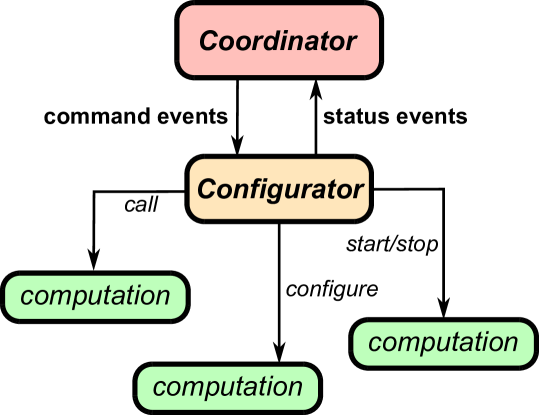
Note that Figure 2 omits the important but complementary concept of a monitor, which is responsible for observing the system and generating events when certain conditions are met or violated.
III Example
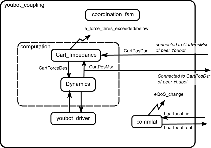
Figure 3 shows the coordination statechart that is executed on each of the two youBots of the coupling application. Figure 4 shows a (slightly simplified) component architecture; straight arrows represent data-flow communication and zigzag lines represent status events emitted by computational components and received by the coordinator. This application is used as a running example throughout this article. It has been converted to the Coordinator–Configurator pattern.
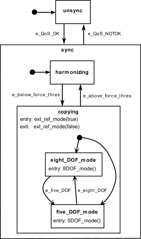
The basic behavior of the demo is immediately visible from the statechart. At the toplevel, the unsync (unsynchronized) state is entered by default and signifies that communication with the peer robot is not functional. After communication is established and its QoS is sufficient, a transition to the sync (synchronized) state takes place, and from there to the harmonizing state. The latter means that the control loop responsible for moving the end-effector of the robot towards the position of the peer robot is operational and the impedance controller Cart_Impedance (see Figure 4) is computing a desired-force control signal. However, since this force is too high, this controller is configured to not output the signal but instead output a desired force of zero in all directions (ext_ref_mode(false). As a result, the robot arm remains controlled in a compliant way, merely compensating for gravity. Only when both arms are (more or less) manually aligned by the operator does the desired force fall beneath the threshold, and thus trigger the transition to the copying state and from there (depending on the configuration) to the eight_DOF_mode or five_DOF_mode. In either case, the coupling is put into effect by requesting the controller to output the control signal ext_ref_mode(true). Alternating between eight_DOF_mode and five_DOF_mode is commanded by the human operator, and reconfigures the Dynamics component to use the holonomic base as additional degrees of freedom or not.
IV Modeling configuration and its application
The main question is how to model a configuration and what the semantics of applying it are. Obviously, a configuration has to be able to express the necessary platform-specific changes required for runtime coordination. For the youBot coupling example, the following Orocos RTT-specific primitives are sufficient:
-
•
Changing the state of a component (e.g. from running to stopped)
-
•
Modifying a property of a component
-
•
Writing a value on a port.
One of the most fundamental design choices is whether to choose a declarative or procedural model to express the behavior of applying these constraints. In a classical coordination model like FSM, the configuration applied when entering one Coordinator state is typically defined in a procedural fashion by using a function that executes several statements. However, in most cases this approach constrains the execution more than is necessary, as there often only exists a partial ordering requirement of the execution of these statements. This accidental introduction of constraints is undesirable, since it obscures the true requirements of the system and hinders maintenance. Thus, in our approach we opted for a purely declarative model of a configuration (apart from a minor deviation described below). This purely declarative approach becomes possible because, outside of the scope of the Configurator, the Coordinator can express ordering requirements by coordinating the Configurator to apply a series of configurations.
Listing 1 shows a single sample configuration written in the Lua based Configurator DSL. A configuration consists of a pre_conf_state and a post_conf_state specification and a list of configuration changes. The first two define to which (runtime) state components shall be brought before and after the actual configuration takes place, while the latter list defines the exact (platform specific) changes to be applied. Note that with respect to ordering of configuration application, the only guarantee made is the following: the run-time states of the components mentioned in pre_conf_state and post_conf_state are set accordingly and in the defined order before resp. after the list of changes is applied. However, no assumptions can be made about the order of applying the individual changes themselves. The _default keyword permits changing the state of all components that have not been mentioned otherwise. If no _default statement is provided, the state of the unmentioned components is not changed.
Using this DSL, the system configurations required by the coordinator of Figure 3 can be modeled as shown in Listing 2.
Since the state changes from unsync to harmonizing do not involve any actions, but merely model the constraints that must be satisfied before the coupling can be activated, these are not visible in the Configurator configuration. The only configurations necessary are for enabling and disabling the coupling (hence to be applied in entry and exit of copying respectively) and for switching between eight and five degrees of freedom.
V Discussion
We have implemented the described DSL and the associated configurator for the Orocos RTT framework. The existing youBot coupling coordination has been refactored to make use of the new Configurator. This approach has solved the shortcomings of the traditional approach: firstly, the coordination model remains free of any software platform-specific actions and can be reused with any other framework, assuming a Configurator and corresponding configuration. Secondly, the actual changes are applied by the Configurator while the Coordinator remains reactive and free to deal with any other situation that may arise. Lastly, failures within the Configurator are isolated from the Coordinator, permitting it to react to the absence of a status event and ultimately improving its robustness. Naturally, this robustness depends on the run-time context of both entities and the worst-case failures possible.
Since the Configurator constitutes an additional level of indirection, the question of the overhead introduced is justified. Obviously, this cannot be answered in general but will mostly depend on the level of distribution between Coordinator, Configurator and configured components. Nevertheless, the Coordinator–Configurator pattern offers an advantage with respect to benchmarking and profiling the Coordination behavior: since the execution of configuration application is localized within a single component, the respective measurements need likewise only to be added once. This avoids the scattering of profiling code across the Coordination model.
Lastly, having a flat map of configurations might be suboptimal in some cases, as for instance when it is necessary to undo a configuration to return to a previous one. With the current model it is necessary to manually specify the inverse configuration, as for instance is the case for enabling and disabling the coupling in Listing 2. One solution to this could be to use a stack of configurations onto which changes can be pushed (applied) and popped (undone) again.
V-A Deployment
Interestingly, the Coordinator–Configurator pattern allows dealing with deployment as a special case of Coordination and Configuration. To that end, the only requirement is to extend the set of configuration actions with the following primitives:
-
•
Creating components
-
•
Destructing components
-
•
Creating connections between components
-
•
Removing connections between components.
That way, deployment can be viewed as coordinating the system through a series of configurations that culminates with the system having reached an initial operational state. Likewise, shutting down the system can be defined as applying a configuration that stops all components followed by one resulting in their destruction. A system, including its rules for deployment, starting up, runtime changes, and shutdown can thus be specified in terms of a single coordination model (which can, itself, be composed from multiple coordination models) and a platform specific Configurator configuration.
V-B Composition
The approach promises to greatly facilitate composition of systems from systems. Any valid pair of Coordinator and platform-specific Configurator configuration can be treated as a subsystem (sometimes called a composite component) that can be used as a building block in a larger system. Nevertheless, for this to work, several questions need to be answered, notably including: what is the interface a subsystem offers, how can the contained coordination model be controlled from the “outside”, and how the controllable transitions can be specified. Answering these questions is outside the scope of this paper.
VI Conclusions
We have described the Coordinator–Configurator pattern that is applicable to complex component-based robot systems. The pattern’s goal is to balance the forces between increased reusability, temporal determinism and robustness on the one hand and simplicity of the Coordinator on the other. The key idea is to separate the responsibility for commanding actions from the responsibility for executing them. While the first remains with the Coordinator, the latter is assigned to a new entity called the Configurator. The idea has been implemented as a Configurator DSL for the Orocos RTT framework.
For future work we intend to focus on adding a complementary DSL to describe the monitor, whose description was omitted in this work, to further explore the outlined relationship between Coordination/Configuration and deployment, and to validate the hypothesis that this pattern greatly facilitates specifying platform-independent coordinators.
References
- [1] J. Eker, J. W. Janneck, E. A. Lee, J. Liu, X. Liu, J. Ludvig, S. Neuendorffer, S. Sachs, and Y. Xiong. Taming heterogeneity—The Ptolemy approach. Proceedings of the IEEE, 91(1):127–144, 2003.
- [2] B. Finkemeyer, T. Kröger, and F. M. Wahl. Executing assembly tasks specified by manipulation primitive nets. Advanced Robotics, 19(5):591–611, 2005.
- [3] E. Gamma, R. Helm, R. Johnson, and J. Vlissides. Design patterns: elements of reusable object-oriented software. Addison-Wesley, Reading, MA, 1995.
- [4] R. Ierusalimschy, W. Celes, and L. H. de Figueiredo. Lua Programming Language. http://www.lua.org, 2012. Last visited 2012.
- [5] M. Klotzbuecher. rFSM statecharts. http://www.orocos.org/rFSM, 2011. Last visited January 2012.
- [6] M. Klotzbuecher, R. Smits, H. Bruyninckx, and J. De Schutter. Reusable hybrid force-velocity controlled motion specifications with executable domain specific languages. In Proceedings of the 2011 IEEE/RSJ International Conference on Intelligent Robots and Systems, pages 4684–4689, San Francisco, California, 2011. IROS2011.
- [7] J. C. Marty, A. E. K. Sahraoui, and M. Sartor. Statecharts to specify the control of automated manufacturing systems. International Journal of Production Research, 36(11):3183–3215, November 1998.
- [8] OMG. Unified Modeling Language (UML) superstructure specification, version 2.4.1. http://www.uml.org/, 2011.
- [9] E. Prassler, H. Bruyninckx, K. Nilsson, and A. Shakhimardanov. The use of reuse for designing and manufacturing robots. Technical report, Robot Standards project, 2009. http://www.robot-standards.eu//Documents_RoSta_wiki/whitepaper_reuse.pdf.
- [10] M. Quigley, K. Conley, B. Gerkey, J. Faust, T. B. Foote, J. Leibs, R. Wheeler, and A. Y. Ng. ROS: an open-source Robot Operating System. In ICRA Workshop on Open Source Software, 2009.
- [11] M. Radestock and S. Eisenbach. Coordination in evolving systems. In Trends in Distributed Systems. CORBA and Beyond, pages 162–176. Springer-Verlag, 1996.
- [12] J. Rosell. Assembly and task planning using Petri nets: A survey. Proceedings of the Institution of Mechanical Engineers, Part B: Journal of Engineering Manufacture, 218:987–994, 2004.
- [13] P. Soetens. A Software Framework for Real-Time and Distributed Robot and Machine Control. PhD thesis, Department of Mechanical Engineering, Katholieke Universiteit Leuven, Belgium, May 2006. http://www.mech.kuleuven.be/dept/resources/docs/soetens.pdf.