Statement of Provenance
This is an author-created, un-copyedited version of an article accepted for publication in Measurement Science and Technology. IOP Publishing Ltd is not responsible for any errors or omissions in this version of the manuscript or any version derived from it. The definitive publisher-authenticated version is available online at http://dx.doi.org/10.1088/0957-0233/24/3/037001 .
Simple feed-through for coupling optical fibres into high pressure and temperature systems
Abstract
A best practice guide for assembling and testing a simple and inexpensive system feeding an optical fibre into a high pressure and temperature environment is presented. A standard Swagelok type connector is tested together with different ferrule materials and a PEEK capillary tube as feed-through. The system proofed to seal an optical fibre during several pressure and temperature cycling experiments up to 500 bar and 180∘C.
pacs:
07.20.Ka, 07.35.+k, 07.60.Vg, 42.81.WgKeywords: feed-through, fibre optic, seals
1 Introduction
In order to use fibre optic sensors in high pressure and temperature applications, a feed-through for the optical fibre must be used to connect the sensors with the readout unit. Several similar approaches are reported for low pressure and high pressure applications. Sealings are established by compression of a plastic material onto the fibre [1] as well as thermal contraction of a shrinking tube [2]. Some authors report soldering an optical fibre to a feed-through. Furthermore, epoxy resin is used to seal optical fibres [3, 4, 5, 6]. Combinations of different methods were tested as well [7]. Unlike solder and resin sealings, compression sealings allow for removing or adjusting the length of the optical fibre to be sealed.
It is known, that a vacuum seal can be established using a standard Swagelok type fitting in combination with a Teflon [8] or an aluminium [9] ferrule. Within this study, this approach is modified an tested for the application at high pressures. Here, a PEEK capillary is used as feed-through for the optical fibre. The capillary is sealed using a standard Swagelok type connector. Conducting simple tensile tests, different ferrule materials are evaluated regarding the required torque to seal the fibre, the repeatability of the sealing and the re-usability of the ferrule and capillary components. Furthermore, optical attenuation measurements at different wavelengths are performed to monitor the influence of the sealing on the optical properties of the fibre. After selecting an appropriate ferrule material, the sealing is tested in a high pressure and temperature (hp/hT) vessel at cyclic pressure and temperature conditions.
2 Experiments
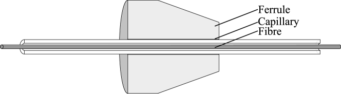
A standard polyimide coated single mode optical fibre (8.3/125/155 m) is used for the experiments. In order to seal the fibre, it is fed through a PEEK capillary tube (inner diameter 180 m) with an additional ferrule (Figure 1). The ferrule is then inserted in to a standard 1/16 in Swagelok type fitting and the fitting is tightened using a torque handle. The sealing, therefore, is established due to the compression of the ferrule and hence of the PEEK capillary on the fibre.
2.1 Tensile Test
Before testing the sealing in a high pressure and high temperature vessel, an appropriate ferrule material is selected based on the results of a simple tensile test. Steel, PEEK, Teflon and Polyimide/Graphite (Pi/Gr 60/40) ferrules are tested. Therefore, the fitting is fixed in a bench vice and the fibre is pulled with a defined force, similar to the force acting on the sealing during a pressure experiment.
The force acting on the fibre during application of high pressure can be calculated according to the relation:
| (1) |
where is the applied pressure and is the cross-sectional area of the fibre. Applying 500 bar to a 155 m fibre, for example, a force of approximately 1 N acts on the fibre. Using a torque handle, different torque values are applied to the Swagelok fitting. Afterwards, the fibre is pulled with a force of 9 N, i.e. 900 safety. For every torque value, the optical attenuation is monitored using optical time domain reflectometry measurements at standard telecommunication wavelengths of 1310 and 1550 nm with a Wavetek MTS6000. Therefore, a fibre optic extension of about 4 km is spliced to the tested fibre.
2.2 hp/hT Test
From the results of the tensile test, a Pi/Gr ferrule is chosen for high pressure and temperature testing (see Section 3). A Swagelok type fitting is mounted to a high pressure and temperature vessel [10] in order to test its performance under cyclic pressures and temperature conditions. Using a pressurizing oil, pressures up to and temperatures up to 180∘C are applied. Again, the optical attenuation is monitored at 1310 and 1550 nm. The schedule of the experiments is listed in Table 1.
-
Time Applied Temperature Applied Pressure h ∘C bar 0 RT 0 19 RT 450 76 RT 500 24 RT 0 24 RT 200 24 150 400 21 170 100 24 50 0 120 170 400 48 180 500 10 RT 0
3 Results
3.1 Tensile Test
The torque, necessary to seal the fibre within the fitting, is listed in Table 2 for the different ferrule materials. It is also indicated if the ferrule can be reused after the experiment, i.e. if it was possible to remove it from the capillary tube. Different ferrule materials exhibit a different mechanical behaviour. Except for the steel ferrule, all ferrule materials passed the tensile test.
-
Material Torque Repeatable Reusable (Nm) Steel - no no PEEK 4 yes no Teflon 2 yes yes Pi/Gr (60/40) 2 yes yes
For different torque values, attenuation measurements were performed at 1310 and 1550 nm. Figure 2 shows the results for a Pi/Gr ferrule and different torques. No influence can be observed at 1300 nm for different torque values. At 1550 nm, a slightly increasing attenuation is observed with increasing torque, indicating increasing mechanical stress on the optical fibre.


3.2 hp/hT Test
After performing the tensile tests, the fitting is mounted to the inside of a high pressure/high temperature vessel. It is fixed with a torque of 2.5 Nm. During the pressure and temperature cycling experiments, neither leaking of oil nor an influence on the measured attenuation can be observed.
4 Discussion and Conclusions
The presented sealing technique proved to be a simple, inexpensive and appropriate for a variety of applications in high pressure and temperature experimentation. Except for the steel ferrule, the different ferrule materials proved to be applicable for a high pressure sealing of an optical fibre during the tensile test. The presented tests show that the optical properties do not change significantly upon compression along the ferrule applying the required torque.
References
References
- [1] M. Ip. High temperature and pressure fiber optic feedthrough for borehole usage, 1990. US Patent 4891640.
- [2] J. S. Butterworth, C. R. Brome, P. R. Huffman, C. E. H. Mattoni, D. N. McKinsey, and J. M. Doyle. A demountable cryogenic feedthrough for plastic optical fibers. Review of Scientific Instruments, 69(10):3697–3698, 1998.
- [3] J. D. Weiss and J. H. Stoever. Vacuum feedthrough for optical fiber cables. Applied Optics, 24(17):2755–2756, Sep 1985.
- [4] W. J. Bock and J. Chrostowski. High-pressure fibre-optic leadthrough system. Journal of Physics E: Scientific Instruments, 21(9):839, 1988.
- [5] R. Bohdan, A. Bercha, P. Adamiec, F. Dybala, and W. Trzeciakowski. A fiber feedthrough for a semiconductor laser located in a high hydrostatic pressure cell. Instruments and Experimental Techniques, 47:422–424, 2004.
- [6] J. S. Cowpe and R. D. Pilkington. Swagelok ultra-torr based feed-through design for coupling optical fibre bundles into vacuum systems. Vacuum, 82(11):1341 – 1343, 2008.
- [7] S. Nishi and N. Takahara. Optical-fiber feedthrough in pressure housing. Selected Areas in Communications, IEEE Journal on, 2(6):923 – 928, nov 1984.
- [8] E. R. I. Abraham and E. A. Cornell. Teflon feedthrough for coupling optical fibers into ultrahigh vacuum systems. Applied Optics, 37(10):1762–1763, Apr 1998.
- [9] D. L. Miller and N. T. Moshegov. All-metal ultrahigh vacuum optical fiber feedthrough. Journal of Vacuum Science & Technology A: Vacuum, Surfaces, and Films, 19(1):386–387, 2001.
- [10] H. H. Milsch, E. Spangenberg, J. Kulenkampff, and S. Meyhöfer. A new apparatus for long-term petrophysical investigations on geothermal reservoir rocks at simulated in-situ conditions. Transport In Porous Media, 74(1):73–85, 2008.