Coupled backward- and forward-propagating solitons in a composite right/left-handed transmission line
Abstract
We study the coupling between backward- and forward-propagating wave modes, with the same group velocity, in a composite right/left-handed nonlinear transmission line. Using an asymptotic multiscale expansion technique, we derive a system of two coupled nonlinear Schrödinger equations governing the evolution of the envelopes of these modes. We show that this system supports a variety of backward- and forward propagating vector solitons, of the bright-bright, bright-dark and dark-bright type. Performing systematic numerical simulations in the framework of the original lattice that models the transmission line, we study the propagation properties of the derived vector soliton solutions. We show that all types of the predicted solitons exist, but differ on their robustness: only bright-bright solitons propagate undistorted for long times, while the other types are less robust, featuring shorter lifetimes. In all cases, our analytical predictions are in a very good agreement with the results of the simulations, at least up to times of the order of the solitons’ lifetimes.
pacs:
41.20.Jb, 42.65.Tg, 78.20.CiI Introduction
Left-handed (LH) metamaterials are artificial, effectively homogeneous structures, featuring negative refractive index at specific frequency bands where the effective permittivity and permeability are simultaneously negative review1 ; review2 ; review3 . In fact, all known realizations of LH metamaterials rely on the use of common right-handed (RH) elements and, thus, in a realistic situation such a composite material features both a LH and a RH behavior, in certain frequency bands. Physically speaking, the difference between the two is that in the LH (RH) regime, the energy and the wave fronts of the electromagnetic (EM) waves propagate in the opposite (same) directions, giving rise to backward- (forward-) propagating waves.
Transmission line (TL) theory constitutes a convenient framework for the analysis of LH metamaterials. Such an analysis relies on the connection of the EM properties of the medium ( and ) with the electric elements of the TL’s unit cell, namely the serial and shunt impedance. As mentioned above, in practice composite right/left-handed (CRLH) structures are quite relevant, giving rise to pertinent CRLH-TL models. These models are, in fact, dynamical lattices which can be used for the description of a variety of metamaterials-based devices and systems, such as resonators, directional couplers, antennas, etc review2 ; review1 ; review3 ; Caloz1 .
Nonlinear CRLH-TLs, with a serial or/and shunt impedance depending on voltages or currents, have also attracted attention. Such structures may be realized by inserting diodes – which mimic voltage-controlled nonlinear capacitors – into resonant conductive elements (such as split-ring resonators) diodes ; Carbonell ; diodes2 . Such nonlinear CRLH-TL models have been used in various works dealing, e.g., with the parametric shielding of EM fields shield , the long-short wave interaction tatar , or soliton formation solTL1 ; solTL2 ; solTL3 . Experiments in nonlinear CRLH-TLs have also been performed (see the review revtl ), and formation of bright BS ; lars or dark lars ; DS envelope solitons, described by an effective nonlinear Schrödinger (NLS) equation, was reported. Notice that in earlier studies on RH-TL models it was shown that two (or more) solitons propagating with the same group velocity, can be described by a system of two (or more) NLS equations inoue1 (see also bilbault for theoretical as well as experimental results). Such coupled NLS equations have been studied extensively in nonlinear optics and mathematical physics; see, e.g., Refs. Remoissenet ; kivagr ; truba and references therein. They are well-known to give rise to a variety of vector solitons, including bright-bright, bright-dark, and dark-dark ones.
In this work, we study analytically and numerically the interaction between backward- and forward-propagating solitons in a nonlinear CRLH-TL. Our model is a nonlinear version of a generic CRLH-TL model (see, e.g., Refs. review2 ; Caloz1 ): the considered nonlinear element in the unit cell of the TL is the shunt capacitor, which simulates the presence of a heterostracture barrier varactor (HBV) diode Carbonell (the capacitance of the HBV diode depends on the applied voltage). Starting from the discrete lump element model of the CRLH-TL, we derive a nonlinear lattice equation. First, we study the linear regime and show that, for certain frequency bands, RH- and LH-modes can propagate with the same group velocity. Next, we treat the nonlinear lattice equation in the framework of the quasi-discrete (or quasi-continuum) approximation (see, e.g., Marquie ; lars ; veldes and Remoissenet for a review): we thus seek for envelope soliton solutions of the nonlinear lattice model, characterized by a discrete carrier and a continuum envelope and employ an asymptotic multi-scale expansion method, to derive a system of two coupled NLS equations. Each of these equations describes the evolution of the envelope of a backward- (LH-) and a forward-propagating (RH-) mode. A systematic analysis of the system of the NLS equations reveals the existence –in certain frequency bands– of three different types of vector solitons: (a) a backward-propagating bright soliton coupled with a forward-propagating bright soliton, (b) a backward-propagating bright soliton coupled with a forward-propagating dark soliton. (c) a backward-propagating dark soliton coupled with a forward-propagating bright soliton, and
The above analytical predictions are then tested against direct numerical simulations, which are performed in the framework of the original nonlinear lattice model. The results of the simulations verify the existence of the aforementioned types of vector solitons in the full TL model, but also offer important information regarding their robustness. In particular, results of direct simulations performed for long times indicate that bright-bright solitons are the most robust among the members of the vector soliton family. Indeed, the mixed (dark-bright or bright-dark) types are found to be less robust; however, the dark-bright solitons in a specific frequency band, although they are deformed during their evolution, are found to be more robust than those in other bands, as well as the bright-dark solitons, which are destroyed for the same propagation time. In any case, our results indicate the existence of all three types, robustness of bright-bright solitons and partial or substantial deformation of the other types. We can thus conclude that bright-bright (LH-RH), as well as dark-bright (LH-RH) solitons in certain frequency bands, have a better chance to be observed in experiments.
The paper is organized as follows. In Section II, we introduce the nonlinear CRLH-TL model and the pertinent lattice equation, and derive the system of the two coupled NLS equations (relevant details are also appended in an Appendix). In Section III, we present analytical and numerical results for each type of vector soliton. Finally, in Section IV, we summarize our conclusions.
II The model and its analytical considerations
II.1 The nonlinear CRLH-TL model
We consider a generic CRLH-TL, composed by both right- and left-handed elements, as shown in its unit-cell circuit shown in Fig. 1 review2 ; Caloz1 . The (RH) elements of this TL are the inductance and capacitance , while the LH ones are the inductance and capacitance . We assume that the TL is loaded with a nonlinear capacitance (, while the capacitance will be assumed to be fixed and voltage independent). This can be implemented by proper insertion of diodes in the TL (see, e.g., pertinent experiments as well as theoretical work in Refs. solTL1 ; solTL2 ; solTL3 ; revtl ; BS ; lars ; DS ); in other words, we assume that the shunt capacitor is nonlinear (see details below).

Let us now consider Kirchhoff’s voltage and current laws for the unit-cell circuit of Fig. 1, which respectively read:
| (1) | |||||
| (2) |
where is the voltage across the capacitance and is the current across the inductor . The above equations, together with the auxiliary equations and , lead to the following system:
| (3) |
To proceed further, we now consider a specific voltage-dependence for the nonlinear capacitance . Here, we will assume that – for sufficiently small values of the voltage – the function can be approximated as follows, via a Taylor expansion:
| (4) |
where is a constant capacitance corresponding to the bias voltage , while and also assume constant values, depending on the particular form of . Below, we will further discuss this approximation, in connection with the HBV diode, used in the experiments described in Ref. revtl (similar varactor-type diodes were also used in the experiments of Ref. diodes2 ).
Next, substituting Eq. (4) into Eq. (3) and using the scale transformations [where ] and , we obtain:
| (5) |
where the constant parameters , and are given by:
| (6) |
In the above expressions, and denote series and shunt frequencies, while denotes the characteristic frequency related to the RH part of the unit-cell circuit, respectively; the above frequencies are defined as:
| (7) |
Note that if , i.e., , then the CRLH-TL is usually referred to as balanced, in the sense that the characteristic impedances of the purely LH- and RH-TL, defined as and , are equal, i.e., review2 . On the other hand, if , i.e., , the LH part of the TL dominates, in the sense that the TL has a more pronounced LH behaviour (the serial branch features a capacitive character while the shunt branch an inductive one). In the opposite case, , i.e., , the RH part of the TL dominates and the TL has a more pronounced RH behaviour (the serial branch features an inductive character while the shunt branch a capacitive one).
It is now relevant to adopt physically relevant parameter values for Eq. (5). For applications in the microwave frequency range (e.g., for microstrip lines review2 or coplanar waveguide structures loaded with SRRs review3 – cf. also Ref. veldes for recent work), typical values of the capacitances and inductances involved in the CRLH structure are of the order of pF and nH, respectively. Here, we will use the values nH, pF, and nH; thus, the frequencies in Eqs. (7) take the values GHz, GHz and GHz. On the other hand, as concerns the parameters involved with the nonlinear capacitor , we assume that the pertinent capacitance corresponds to a HBV diode, which is characterized by the following equation Carbonell (see also diodes2 , where the same form of is used, but different parameter values):
| (8) |
where fF/m2 is the capacitance corresponding to bias voltage V, m2 is the device area, V is the breakdown potential, and the exponent results from fitting experimental data. It is clear that, for sufficiently small , by Taylor expanding Eq. (8) one obtains Eq. (4), where the constant parameter values involved are pF, pF/V and pF/V2. To this end, the values of the normalized parameters , and appearing in Eq. (5) take the following values:
| (9) |
Below, we will use these values for the purposes of our analytical and numerical considerations (we have checked that other values lead to qualitatively similar results). Notice that our choice leads to , i.e., we consider the case where the TL has a more pronounced LH character; however, when considering the linear setting (see next subsection), this parameter will also assume other values, corresponding to the balanced and RH-dominated behaviour as well.
II.2 Linear analysis
 |
 |
 |
We now assume plane wave solutions of Eq. (5), of the form , where and denote the wave number and angular frequency, respectively, while the amplitude of the wave is . Substituting the above ansatz into Eq. (5), and keeping only the linear terms in , we obtain the following linear dispersion relation:
| (10) |
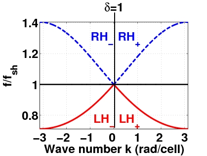
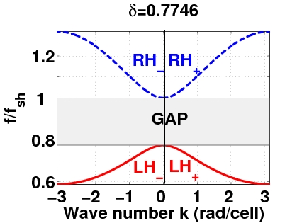
The above result is illustrated in Fig. 2, where we plot the frequency as a function of the wave number (in rad/cell), for three different values of (note that here we consider one period of , i.e., ). It is clear that for (top panel) there exist two frequency bands where EM wave propagation is possible: the RH-band [high-frequency band depicted by dashed (blue) line], for , and the LH-band [low-frequency band depicted by solid (red) line], for . In the same case (), there exists a gap for , where EM wave propagation is not possible.
In the case where (corresponding, e.g., to the value pF) the gap vanishes (cf. middle panel of Fig. 2) and the TL is balanced. In the balanced case, EM wave propagation is possible in two frequency bands as well: the RH-band [high-frequency band – cf. dashed (blue) line] with and the LH-band [low-frequency band – cf. solid (red) line] with .
Finally, for (corresponding, e.g., to pF), a gap appears again for (bottom panel of Fig. 2). In this case too, there exist a RH-frequency band and a LH-frequency band, for and , respectively. Note that in all cases, the RH± and LH± branches correspond to positive or negative , respectively.
Thus, generally, in the linear setting – and for a given frequency – the EM waves may either propagate in the RH region (forward wave propagation) or in the LH region (backward wave propagation). However, in the nonlinear setting, coupling between modes propagating in the LH and RH regime is possible (see, e.g., relevant earlier work in Refs. inoue1 ; bilbault ). Below we will demonstrate that this is the case indeed, and study the coupling (interaction) between LH and RH modes with equal group velocities. Since the latter are tangents in the dispersion curves, inspection of Fig. 2 shows that it is possible to identify domains, belonging to the RH± and LH∓ branches, exhibiting parallel tangents, i.e., equal group velocities.
To further elaborate on this, we may use Eq. (10) to obtain the group velocity :
| (11) |
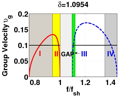
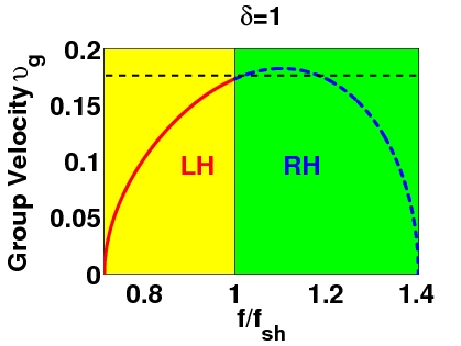
In Fig. 3, we show the dependence of the group velocity on the normalized frequency , for the values of used in Fig. 2. Notice that the figure depicts only the group-velocity branches with – see solid (red) and dashed (blue) lines – corresponding, respectively, to the LH- and RH+ branches of the dispersion curves; the branches with (pertinent to the LH+ and RH- branches of the dispersion curve) are mirror symmetric with respect to the ones shown in the figure, due to the parity of the dispersion relation.
 |
 |
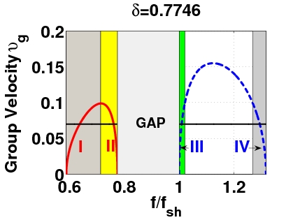 |
Considering a horizontal cut of the group-velocity curves, say at or (see horizontal lines in the top and bottom panels of Fig. 3), it is readily observed that, indeed, a LH- and a RH+ mode can share a common group velocity (and interact in the nonlinear regime, as mentioned above). In fact, inspection of the group-velocity curves, say in the top panel of Fig. 3, shows that the maximum possible common is given by , the local maximum of , occurring at , in the (shorter in height) LH frequency band. Then, one can divide each of the LH and RH group-velocity curves into two sub-regions, depending on the sign of the group-velocity dispersion (GVD), , where such coupling with equal group velocities may occur. These subregions are: (a) the sub-bands I () and II () for the LH-frequency band, characterized by positive and negative GVD respectively, and (b) the sub-bands III () and IV () for the RH-frequency band, again characterized by positive and negative GVD respectively. Thus, nonlinear LH and RH modes of equal can feature the following four different possible interactions:
-
1.
LH-mode in band II and RH-mode in band IV, both featuring negative GVD.
-
2.
LH-mode in band I and RH-mode in band IV; here, the LH (RH) mode features positive (negative) GVD.
-
3.
LH-mode in band I and RH-mode in band III, both featuring positive GVD.
-
4.
LH-mode in band II and RH-mode in band III; here, the LH (RH) mode features negative (positive) GVD.
It is clear that the above set of possibilities arises from the existence of the gap in the considered case with . A similar situation also occurs for , e.g., for as in the bottom panels of Figs. 2 and 3. On the other hand, for the gap does not longer exist and, thus, the only possible interaction is between a LH-mode with positive GVD and a RH-mode with negative GVD; this interaction can occur for group velocities , i.e., beneath the dashed horizontal line in the middle panel of Fig. 3. This possibility, however, is already taken into regard – cf. case (2) above; furthermore, soliton formation in the balanced CRLH-TL () has already been studied in the literature solTL2 . For these reasons, below we will proceed by analyzing the case corresponding to , which offers all possible scenarios; it is clear that the case of shares similar qualitative features; this similarity extends beyond the linear wave case and into the nonlinear solitonic one.
Although, as explained above, we are not going to analyze soliton formation and soliton in the special case of the balanced CRLH-TL with , it is worth mentioning the following. In the case of , the dispersion relation exhibits a Dirac point, namely it is approximately linear in the vicinity of , i.e., – cf. middle panel of Fig. 2. The emergence of Dirac points is particularly interesting in the two-dimensional (2D) setting of triangular and hexagonal lattices arising in different contexts, such as optics as , atomic Bose-Einstein condensates carr , and the so-called photonic graphene graph . This has also led to an interest in this subject from a rigorous mathematical perspective miw . It is thus quite interesting that, in principle, 2D balanced CRLH-TLs may host a variety of fundamental effects, such as conical diffraction, formation of topological defects, and even phase transitions, as in Refs. as ; carr ; graph .
II.3 Nonlinear analysis: the coupled NLS equations
To describe the coupling between a RH and a LH nonlinear mode with equal group velocities, we will use the quasi-discrete approximation, which takes into regard the inherent discreteness of the system (see, e.g., Ref. Remoissenet for a review, and Refs. lars ; veldes for relevant recent work). Generally, this approach allows for the description of quasi-discrete envelope solitons (usually satisfying an effective NLS model), characterized by a discrete carrier and a slowly-varying continuum envelope. In our case, since we are interested in the description of two different modes, we seek for a solution of Eq. (5) in the form:
| (12) |
where “c.c.” denotes complex conjugate. In Eq. (12), subscripts correspond to the LH and RH mode, are unknown (continuous) slowly-varying envelope functions depending on the slow scales (where is the common group velocity) and , while , with , are the (discrete) carriers of frequencies and wavenumbers . Finally, is a formal small parameter setting the field amplitude and the slow scales of the envelope functions.
At this point, we should note that the field as expressed in Eq. (12) is, in fact, the leading-order form of a more general ansatz employing multiple time and space scales. In this context, use of a formal multi-scale expansion method leads to a hierarchy of equations at various powers of , which are solved up to the third-order. Here, we will present the main results and provide further details in the Appendix A. Particularly, from the first- and second-order problems [i.e., at orders (linear limit) and , respectively] we derive the dispersion relation, Eq. (10), and the group velocity, Eq. (11). Finally, at the next order, , we obtain the following coupled NLS equations:
| (13) | |||
| (14) |
where the normalized GVD coefficients , the self-phase modulation (SPM) coefficients , and the cross-phase modulation (CPM) coefficients (with ) are respectively given by:
| (15) | |||||
| (16) | |||||
| (17) |
and the coefficients and are defined in Appendix A. Next, using scale transformations, we measure normalized time and densities in units of and respectively, and cast Eqs. (13)-(14) in the form:
| (18) | |||
| (19) |
where
| (20) |
As seen from Eqs. (18), in the absence of coupling () the evolution of either the LH mode or the RH mode is described by a single NLS equation; the latter, supports soliton solutions of the dark or the bright type, depending on the relative signs of dispersion and nonlinearity coefficients (see, e.g., Ref. kivagr ). Particularly, the mode () supports dark solitons for () or bright solitons for (). These conditions, however, are modified for and various types of coupled (alias vector) solitons can be found in the full version of Eqs. (18). Below we will present these types of coupled backward- and forward-propagating solitons, belonging, respectively, to the LH and RH frequency bands.
Before proceeding with the presentation of the coupled soliton solutions we make the following comments. First, in some cases, solitons will be found in a stationary form. However, using these stationary solutions, one can also find travelling soliton solutions, with an additional free parameter, i.e., the velocity , by means of the following Galilean boost:
| (21) | |||||
| (22) | |||||
Second, it is interesting to note that, contrary to what is often the case in the mathematically studied multi-component variants of the NLS equation truba , the model of Eqs. (18)-(19) does not necessarily respect the condition . The latter condition ensures the existence of an underlying Hamiltonian structure and is customary in other physical applications (such as atomic physics emergent ). Nevertheless, as we will see below, this is not a necessary condition for the existence of the exact solutions considered below.
III Soliton interactions in different frequency bands. Numerical results
III.1 Numerical procedure.
Let us now proceed to study numerically the evolution of the coupled solitons presented in the previous section in the framework of the fully discrete model of Eq. (5).
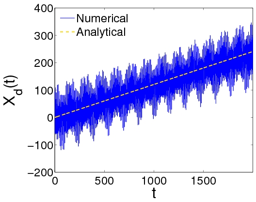
In order to compare the analytical approximations with the results of numerical simulations, we will make use of two diagnostic quantities: the first one is the evolution of the center of mass defined as:
| (23) |
and the second one, is a power-like quantity defined as:
| (24) |
with being the lattice size. The above quantities can readily be determined for each type of vector solitons that is predicted analytically in the framework of the coupled NLS equations.
In all simulations, which have been performed by means of a fixed-step 4th-order Runge-Kutta scheme with a time step equal to 0.01, we have fixed the value of the small parameter as , and we have used periodic boundary conditions. Use of the latter leads to the requirement that the wavenumber of a dark soliton component must be equal to , with and also being odd.
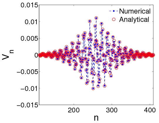
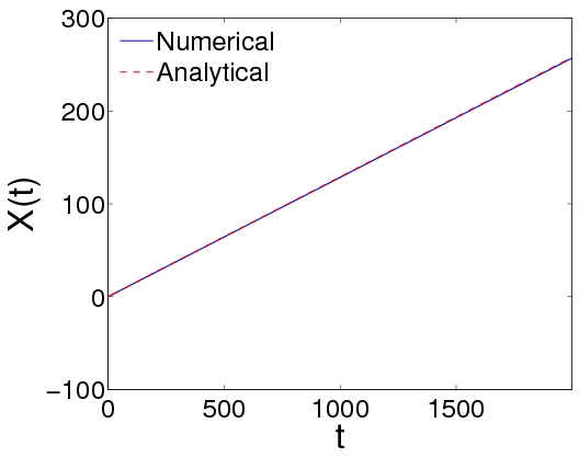
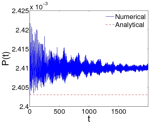
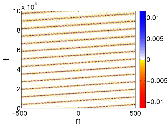
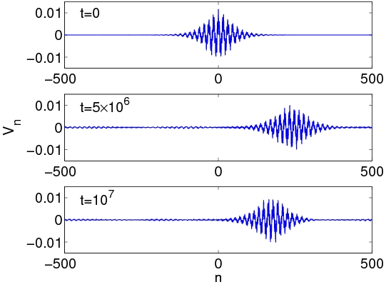
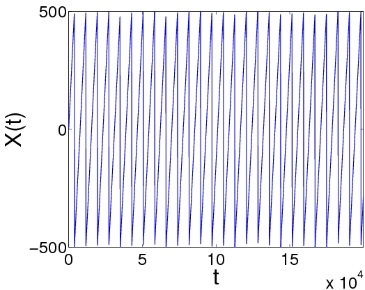
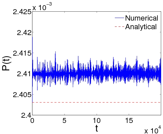
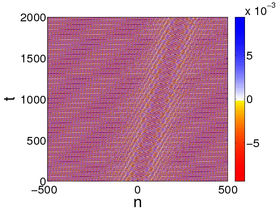
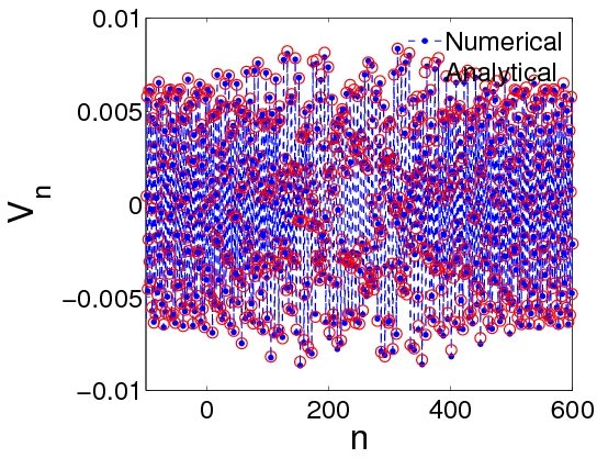
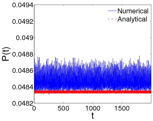
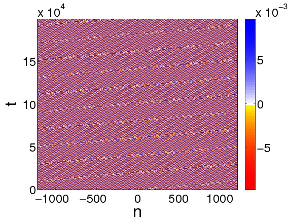
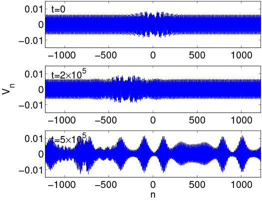
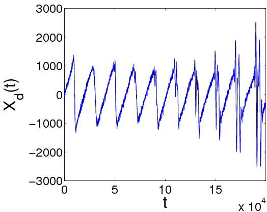
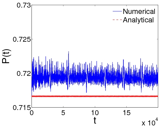
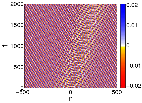
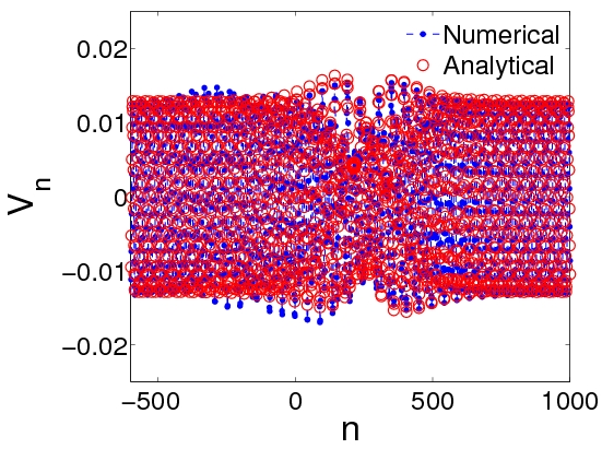
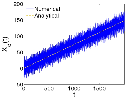
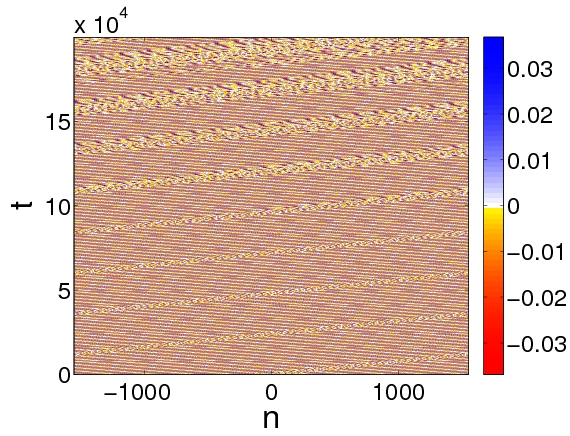
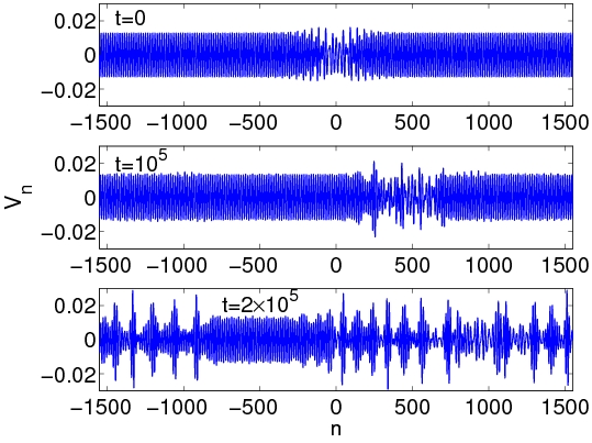
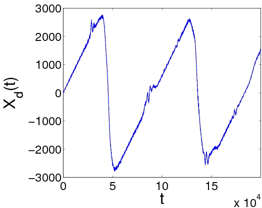
In all figures below (Figs. 5-15), except if stated otherwise, we show the density plots of , the spatial profile of at , as well as the time evolution of the center of mass and the quantity .
Regarding the evolution time of the simulations, we should note the following. Most of our simulations are performed for relatively large normalized times – typically up to in some cases. However, given our time normalization, the physical unit time (set by the frequency GHz) is very small, namely picoseconds (see Sec. II.A). Actually, since all characteristic frequencies of the system (see Eq. (7)) are in the microwave regime, all characteristic times are less than a nanosecond and, thus, obviously, simulations for time even of the order of are extremely time-consuming. Nevertheless, our results for normalized times up to (corresponding to a physical time of the order of a tenth of millisecond), demonstrate a good agreement with our analytical predictions in suitable cases (see below). Furthermore, the results of such long simulations can also be used as a reliable indication of the solitons’ robustness. Hence, in the case where the solitary waves are found to be very robust, we expect that they would survive for the longer time scales that would render them experimentally observable.
III.2 Bright-bright solitons in bands II and IV.
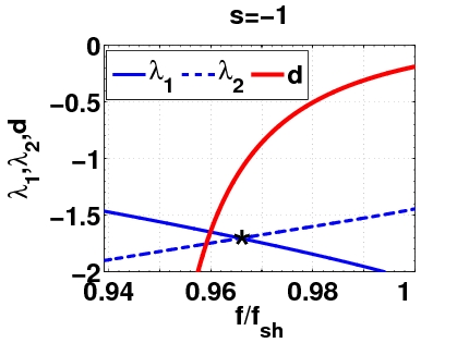
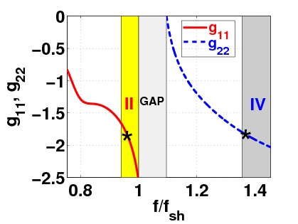
First, we consider the interaction between a backward propagating soliton, with a frequency lying in band II, and a forward propagating soliton, with a frequency lying in band IV. In this case, (cf. Fig. 3), while the other dispersion and nonlinearity coefficients are shown in Fig. 4 as functions of the normalized frequency (for ). It is observed that , and also , while the dispersion coefficient takes values . Thus, to a first approximation, the system of Eqs. (18)-(19) takes the form:
| (25) | |||
| (26) |
where and , as can be seen in the top panel of Fig. 4. The above system is generally non-integrable and soliton solutions can not be found in an explicit analytical form. However, there exists a specific frequency value, namely where the dispersion coefficient take the value and the nonlinearity coefficients take the values (see the intersection point of the relevant curves depicted by a star in the top panel of Fig. 4). This case corresponds to a (common for both components) group velocity , which occurs when the (normalized) carrier frequencies for the modes and take, respectively, the values (as mentioned above) and . Then, symmetric bright-bright standing soliton solutions can be found in the following form (see, e.g., Ref. yang ):
| (27) |
where is an arbitrary parameter. Using the above expressions, we can now approximate the unknown voltage in Eq. (5), in terms of the original coordinates and , as follows:
| (28) | |||||
where functions and have the following form:
| (29) | |||
| (30) |
while the solution amplitude and the frequencies () are given by:
| (31) | |||
| (32) |
with . Now, substituting Eq. (28) into Eqs. (23) and (24) and supposing that is small enough, we obtain for our diagnostic quantities:
| (33) | |||||
| (34) |
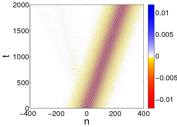
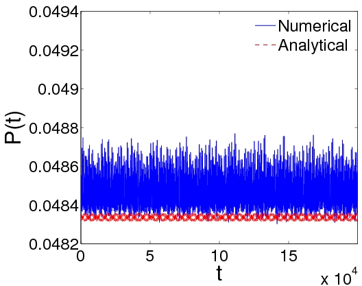
In Figs. 5 and 6 we show the outcome of the simulations for short and long times, respectively, of a bright-bright soliton with and . The parameters used are and , which gives and , i.e., a bright-bright soliton in bands II and IV. In Fig. 5, it is evident that the agreement between analytical and numerical results pertaining to the soliton profile, and the evolution of the center of mass and power diagnostics, is very good. In the case shown in Fig. 6, we have performed a very long simulation, up to normalized times . It is clear that that the initial pulse does not spread out, which indicates the soliton robustness: the top panels of the figure – and particularly the snapshots of the pulse profile at – clearly show that the soliton persists as a stable object up to the end of this long simulation time. We note in passing that a fragment of the soliton is backscattered when the soliton starts its motion at (due to the approximate nature of our analytical solution profile). Notice that despite this emission and the subsequent interaction of the fragment with the “distilled” solitary wave, the coherent structure remains robust and preserves its characteristics throughout the evolution thereafter.
 |
 |
 |
 |
 |
 |
 |
 |
III.3 Bright-dark solitons in bands I and IV
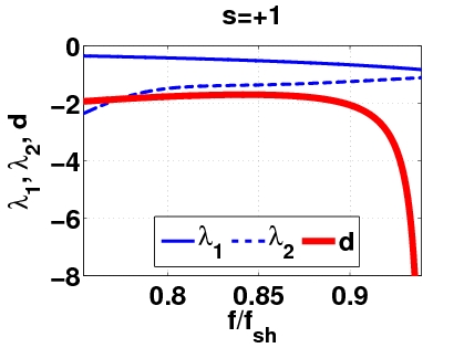
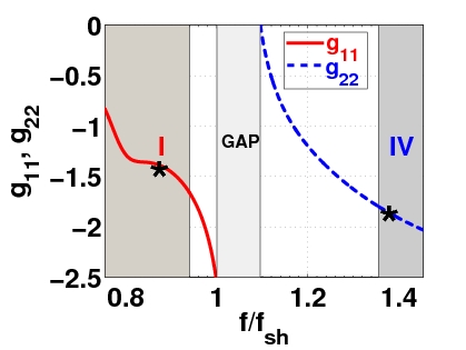
Next, we consider the interaction between a backward propagating soliton, with a frequency lying in band I, and a forward propagating soliton, with a frequency lying in band IV. In Fig. 7 we show the dependence of the parameters , and (top panel), as well as of the nonlinearity coefficients (bottom panel), on the normalized frequency (for ). In this case, (cf. Fig. 3), while and, thus, Eqs. (18)-(19) are reduced to the form:
| (35) | |||
| (36) |
where and , as can be seen in the top panel of Fig. 7. The above equations are no longer of the Manakov type and, thus, generally, they are not completely integrable. Nevertheless, standing wave solutions can still be found in the form of coupled bright-dark solitons, with the frequency of the bright (dark) soliton component being in the LH (RH) frequency band. Therefore, here we have a case of coupled solitons, a backward-propagating bright soliton and a forward-propagating dark soliton, whose exact analytical form is:
| (37) | |||||
| (38) |
where the soliton amplitude parameters and the inverse width are connected via the following equations:
| (39) | |||
| (40) |
with in the considered LH frequency band (notice that as well). It is thus clear that the above solutions are characterized by one free parameter.
 |
 |
 |
 |
 |
 |
 |
 |
Employing the solutions (37)-(38), we can again approximate a solution of Eq. (5) for the voltage , in terms of the original coordinates and , as follows:
| (41) | |||||
where
| (42) | |||
| (43) |
In this case, the solution amplitude and the frequencies () are given by:
| (44) | |||||
| (45) |
In order to get an expression for the center of mass similar to that of the bright-bright soliton (34), we must define it as:
| (46) |
where
| (47) |
Substituting Eq. (41) into Eqs. (46) and (24) we can once again obtain relevant expressions (provided that is small enough) for the center of mass and power:
| (48) |
| (49) |
Figures 8 and 9 show the evolution of a bright-dark soliton (and its characteristics) in bands I and IV with and . The parameters used are and , which give and . In this case, it is clear that although bright-dark solitons do exist, the agreement between analytical and numerical results becomes worse over time. Also, as shown in the top right panel of Fig. 9, the pulse profile indicates that the bright-dark soliton is not a robust object. In particular, at time , it is clear that the configuration has dramatically changed its character.
III.4 Dark-bright solitons in bands I-III and II-III
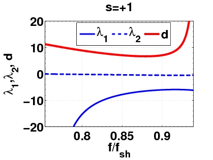
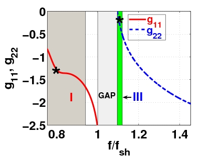
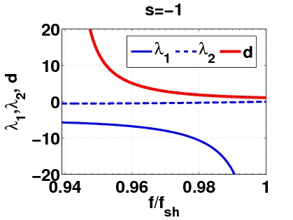
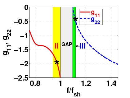
Finally, we consider the cases of coupled solitons in bands I and III, and also in bands II and III. In both cases, as is observed in the top panels of Figs. 10 (bands I-III) and 11 (bands II-III), we have that the parameter . Now, the NLS equations for and take the following form:
| (50) | |||
| (51) |
where () corresponds to solitons in bands I and III (II and III). Note that, in this case, , while and , as shown in Figs. 10 and 11. As in the previous case, the equations (50)-(51), generally, are not completely integrable. Nevertheless, standing wave solutions can still be found in the form of coupled dark-bright solitons, with the frequency of the dark (bright) soliton component being in the LH (RH) frequency band; therefore, here we have a case of a backward-propagating dark soliton, coupled with a forward-propagating bright soliton, whose exact analytical forms are:
| (52) | |||||
| (53) |
where the soliton amplitude parameters and the inverse width are connected via the following equations:
| (54) | |||
| (55) |
 |
 |
 |
 |
 |
 |
 |
 |
Following our previous considerations, we may again use the above solutions and approximate the voltage in Eq. (5), in terms of the original coordinates, as follows:
| (56) | |||||
where functions and are given by:
| (57) | |||||
| (58) |
while the rest of the soliton parameters are:
| (59) | |||
| (60) |
 |
 |
 |
 |
 |
 |
 |
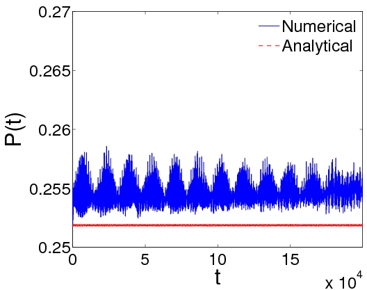 |
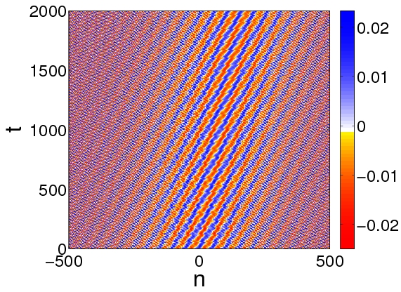
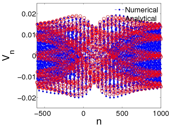
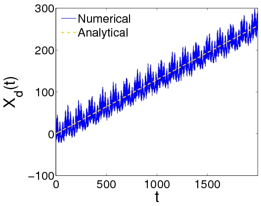
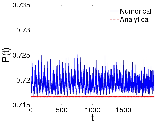
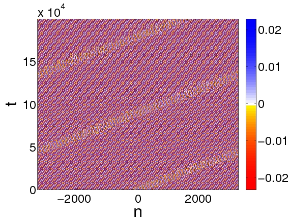
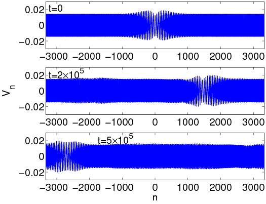
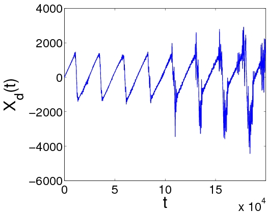
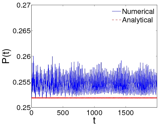
Figures 12 and 13 show the outcome of the simulations for a dark-bright soliton in bands I and III (with and ), while Figs. 14 and 15 correspond to a dark-bright soliton in bands II and III (with and ). The parameters used are and , which gives and , in bands I and III, and and , which gives and , in bands II and III, respectively. In the latter case, the relatively large values of the number of particles and of used are motivated by the necessity of a vanishing tail for the bright component at the edges of the lattice. As seen in this set of figures, dark-bright solitons in bands II-III and I-III do exist, as predicted in theory. Furthermore, it is observed that the former are less robust than the latter, as seen both from their stronger deformation and the fact that they “lose” their solitary wave character earlier. This can be observed, e.g., in the strong fluctuations in the evolution of the soliton center in the bottom left panel of Fig. 15, or perhaps most notably in the substantial modification of the wave profile upon long propagation in the top right panel of the same figure. On the other hand, the dark-bright solitons of bands I-III seem to essentially preserve their structure even in the long evolution of Fig. 13.
IV Conclusions
In conclusion, we have used both analytical and numerical techniques to study the existence, stability and dynamics of coupled backward- and forward-propagating solitons in a composite right/left-handed (CRLH) nonlinear transmission line (TL). The considered form of the TL was a quite generic one, finding applications to the modelling of a wide range of LH systems and devices, with “parasitic” RH behavior, such as resonators, antennas, directional couplers, among others review2 ; review1 ; review3 ; Caloz1 .
Our analysis started with the derivation of a nonlinear lattice equation governing the voltage across the fundamental (unit cell) element of the transmission line. In the linear regime, we derived the dispersion relation for small-amplitude linear plane waves and showed that they may either propagate in a right-handed (RH) high-frequency region, or in a left-handed (LH) low-frequency region. We also identified frequency bands where RH- and LH-modes can propagate with the same group velocity.
Using the above result, we then investigated the possibility of nonlinearity-assisted coupling between LH- and RH-modes. This way, in order to analytically treat the nonlinear lattice equation, we used the so-called quasi-discrete approximation. The latter is a variant of the multi-scale perturbation method, which takes into regard the discreteness of the system by considering the carrier (envelope) of the wave as a discrete (continuum) function of space. Employing this approach, we derived, in the small-amplitude approximation and for certain space- and time-scales, a system of two coupled nonlinear Schrödinger (NLS) equations for the unknown voltage envelope functions. This system was then used to predict the existence of coupled backward- and forward-propagating solitons, of the bright-bright, bright-dark and dark-bright type, respectively.
The above existence results, as well as the propagation properties and the potential robustness of these vector solitons, were then investigated for each of the possible scenarios. This was done by means of direct numerical simulations of the full CRLH-TL nonlinear lattice model, using as initial conditions the analytical forms of solitons predicted by the perturbation theory. In the simulations, apart from the evolution of the shape, we also studied the evolution of the center of mass and a power-like quantity of the various solitons. Our numerical results have confirmed the existence of the various types of solitons predicted analytically, but have also revealed their distinct robustness characteristics. In particular, we found that bright-bright solitons feature a robust propagation over long times. On the other hand, as concerns solitons of the mixed-type (namely dark-bright and bright-dark ones), we found that, in specific frequency bands (bands I-III), dark-bright solitons are more robust than those in other bands (i.e., II-III) or bright-dark solitons: dark-bright solitons in bands II-III and bright dark solitons preserve their shape only for finite times and, for sufficiently long evolutions, they are either destroyed (bright-dark) or are significantly deformed (dark-bright).
We can thus postulate that from all types of solitons predicted analytically, bright-bright and dark-bright ones (in bands I-III) are the most likely ones to be experimentally observable. In all cases, our numerical results were found to corroborate the analytical predictions, at least up to the times during which the solitary waves propagate robustly.
It would be interesting to study other types of nonlinear CRLH-TL lattice models modelling realistic structures composed by LH-metamaterials. In that regard, a pertinent interesting direction would be the investigation of the effects of damping and driving, which may lead to robust nonlinear waveforms which would constitute dynamical attractors in such settings. Additionally, the study of higher-dimensional settings is a particularly challenging problem. In the latter context, in addition to simpler (yet genuinely higher dimensional, or even quasi-one-dimensional) solitary wave structures, more complex waveforms may be realizable such as vortices. The exploration of such states and their dynamical robustness will be reported in future publications.
Acknowledgments. The work of D.J.F. was partially supported by the Special Account of Research Grants of the University of Athens. J.C. acknowledges financial support from the MICINN project FIS2008-04848. PGK acknowledges support from the US-NSF via CMMI-1000337, and the US-AFOSR via FA9550-12-1-0332.
Appendix A The perturbation scheme
Our analytical approximation relies on the use of the quasi-continuum approximation, which is a variant of the method of multiple scales Jeffrey . We introduce new independent temporal variables, (), and accordingly expand the time derivative operator as . Next, we seek solutions of Eq. (5) in the form:
| (61) |
Then, we substitute Eq. (61) into Eq. (5) and employ a continuum approximation for the envelope functions , i.e., , where and being the lattice spacing (the latter parameter does not appear in the results below, as one may readily rescale as ).Furthermore, we introduce the new spatial variables and, thus, . To this end, equating coefficients of like powers of , we obtain the following (first three) perturbation equations:
| (62) | |||||
| (63) | |||||
| (64) |
where the operators are given by
| (65) | |||||
| (66) | |||||
| (67) | |||||
| (68) |
We now seek for a solution of the linear problem, Eq. (62), in the form:
| (69) |
where subscripts and correspond to the LH and RH frequency bands, is an unknown complex function, , while the wavenumbers and frequencies satisfy the dispersion relation provided in Eq. (10).
Next, substituting Eq. (69) into Eq. (63), we obtain the non-secularity condition for :
| (70) |
which suggests that , where , while the group velocities result self-consistently as [cf. Eq. (11)]. Employing Eq. (70), we may determine from Eq. (63), for , the unknown field :
| (71) |
where functions are given by:
| (72) | |||||
| (73) | |||||
| (74) | |||||
On the other hand, functions can be derived at the order , by means of the equation:
| (75) |
which leads to the result:
| (76) |
To this end, we arrive at the following expression for :
| (77) |
where
| (78) | |||||
| (79) | |||||
| (80) | |||||
| (81) |
Finally, defining the coefficients:
| (82) | |||||
| (83) |
and using the variables and , we derive from the non-secularity condition at the coupled NLS equations (18).
References
- (1) G. V. Eleftheriades and K. G. Balmain (eds.) Negative-Refraction Metamaterials. Fundamental Principles and Applications (John Wiley, New Jersey, 2005).
- (2) C. Caloz and T. Itoh, Electromagnetic Metamaterials: Transmission Line Theory and Microwave Applications (Wiley, NJ, 2006).
- (3) R. Marqués, F. Martín, and M. Sorolla, Metamaterials with negative parameters. Theory, Design, and Microwave Applications (John Wiley and Sons, NJ, 2008).
- (4) A. Lai, C. Caloz, and T. Itoh, IEEE Microwave Magazine 5, 34 (2004).
- (5) M. Lapine, M. Gorkunov, and K. H. Ringhofer, Phys. Rev. E 67, 065601 (2003); M. Lapine and M. Gorkunov, Phys. Rev. E 70, 066601 (2004); B. Wang, J. Zhou, T. Koschny, and C.M. Soukoulis, Opt. Express 16, 16058 (2008); D. A. Powell, I. V. Shadrivov, and Yu. S. Kivshar, Appl. Phys. Lett. 95, 084102 (2009).
- (6) J. Carbonell, V. E. Boria and D. Lippens, Microwave Opt. Tech. Lett. 50, 474 (2008).
- (7) A. P. Slobozhanyuk, P. V. Kapitanova, I. V. Shadrivov, P. A. Belov, and Yu. S. Kivshar, JETP Lett. 95, 613 (2012).
- (8) S. Feng and K. Halterman, Phys. Rev. Lett. 100, 063901 (2008).
- (9) A. Chowdhury and J. A. Tataronis, Phys. Rev. Lett. 100, 153905 (2008).
- (10) A. B. Kozyrev and D. W. van der Weide, IEEE Trans. Microw. Theory Tech. 53, 238 (2005).
- (11) K. Narahara, T. Nakamichi, T. Suemitsu, T. Otsuji, and E. Sano, J. Appl. Phys. 102, 024501 (2007).
- (12) S. Gupta and C. Caloz, in: IEEE MTT-S Int. Microw. Symp. (IMS), 979 (2007); D. Yemélé and F. Kenmogné, Phys. Lett. A 373, 3801 (2009).
- (13) A. B. Kozyrev and D. W. van der Weide, J. Phys. D: Appl. Phys. 41, 173001 (2008).
- (14) J. Ogasawara and K. Narahara, IEICE Electron. Express 7, 608 (2010).
- (15) L. Q. English, S. G. Wheeler, Y. Shen, G. P. Veldes, N. Whitaker, P. G. Kevrekidis, and D. J. Frantzeskakis, Phys. Lett. A 375, 1242 (2011).
- (16) Z. Wang, Y. Feng, B. Zhu, J. Zhao, and T. Jiang, J. Appl. Phys. 107, 094907 (2010).
- (17) Y. Inoue, N. Sugimoto, and T. Kakutani, J. Phys. Soc. Jpn. 43, 243 (1977); T. Yosinaga, N. Sugimoto and T. Kakutani, J. Phys. Soc. Jpn. 50, 2122 (1981).
- (18) J. M. Bilbault, P.Marquié, and T. B. Michaux, Phys. Rev. E 51, 817 (1995); P. Marquié, J. M. Bilbault, and M. Remoissenet, Phys. Rev. E 51, 6127 (1995).
- (19) M. Remoissenet, Waves called solitons (Springer, Berlin, 1999).
- (20) Yu. S. Kivshar and G. P. Agrawal, Optical solitons: From fibers to photonic crystals (Academic, San Diego, 2003).
- (21) M.J. Ablowitz, B. Prinari and A.D. Trubatch, Discrete and Continuous Nonlinear Schrödinger Systems, Cambridge University Press (Cambridge, 2004).
- (22) P. Marquie, J. M. Bilbault, and M. Remoissenet, Phys. Rev. E 49, 828 (1994).
- (23) G. P. Veldes, J. Cuevas, P. G. Kevrekidis, and D. J. Frantzeskakis, Phys. Rev. E 83, 046608 (2011).
- (24) M. J. Ablowitz, S. D. Nixon, and Y. Zhu, Phys. Rev. A 79, 053830 (2009); O. Bahat-Treidel, O. Peleg, M. Segev, and H. Buljan, Phys. Rev. A 82, 013830 (2010).
- (25) L. H. Haddad and L. D. Carr, Physica D 238, 1413 (2009); C. Becker, P. Soltan-Panahi, J. Kronjäger, S. Dörscher, K. Bongs, and K. Sengstock, New J. Phys. 12 065025 (2010).
- (26) M. I. Molina and Yu. S. Kivshar, Opt. Lett. 35, 2895 (2010); M. J. Ablowitz and Y. Zhu, Opt. Lett. 36, 3762 (2011).
- (27) C.L. Fefferman and M.I. Weinstein, arXiv:1202.3839. see also arXiv:1212.6072.
- (28) P. G. Kevrekidis, D. J. Frantzeskakis and R. Carretero-González (Eds.), Emergent Nonlinear Phenomena in Bose-Einstein Condensates, (Springer-Verlag, Heidelberg, 2008); R. Carretero-González, D. J. Frantzeskakis, and P. G. Kevrekidis, Nonlinearity 21, R139 (2008).
- (29) J. Yang, Physica D 108, 92 (1997).
- (30) A. Jeffrey and T. Kawahara, Asymptotic Methods in Nonlinear Wave Theory (Pitman, Boston, 1982).