Ultrafast QND measurements based on diamond-shape artificial atom
Abstract
We propose a Quantum Non Demolition (QND) read-out scheme for a superconducting artificial atom coupled to a resonator in a circuit QED architecture, for which we estimate a very high measurement fidelity without Purcell effect limitations. The device consists of two transmons coupled by a large inductance, giving rise to a diamond-shape artificial atom with a logical qubit and an ancilla qubit interacting through a cross-Kerr like term. The ancilla is strongly coupled to a transmission line resonator. Depending on the qubit state, the ancilla is resonantly or dispersively coupled to the resonator, leading to a large contrast in the transmitted microwave signal amplitude. This original method can be implemented with state of the art Josephson parametric amplifier, leading to QND measurements in a few tens of nanoseconds with fidelity as large as 99.9%.
Superconducting circuits have demonstrated in the last decade their high ability to perform coherent quantum experimentsKorotkov_QIP2009 ; Clarke_Nature2008 . Relaxation and coherence times are continuously increasing Paik_PRL2011 . In addition, these quantum systems benefit from very strong coupling with the electromagnetic field, and potential scalability. Finally the circuit parameters that define the quantum dynamics are tunable and adjustable on demand, which makes them very promising candidates to process quantum information on chip. In this framework, the ability to perform ultrafast single shot read-out of a quantum bit is highly desirable. Up to now, high one shot fidelity was obtained by switching quantum measurements using escape process Lucero_PRL2008 , the intrinsic drawback of this method being its destructiveness. Quantum Non Demolition (QND) measurements are performed by coupling the qubit dispersively to a resonator Wallraff_PRL2005 . The qubit acts as a state-dependent refractive index that shifts the cavity frequency, and the measurement is performed by probing the resonator with an external microwave. QND character is preserved as long as one remains in the dispersive regime, keeping the photon population of the resonator below a critical valueBoissonneault_PRA2009 , and also limiting the incident power. Low temperature amplifiers have thus to be used to reach high fidelity. On the other hand, using non-linear resonator and bifurcationSiddiqi_PRB2006 ; Mallet_naturephys2009 or Jaynes-Cummings non linearityReed_PRL2010 allows to reach one shot high fidelity read-out, but at the price of lower QND fidelity. Thanks to recent advances in parametric amplification using Josephson junction circuits Clerk_RMP2010 ; Bergeral_Nature2010 ; Roch_PRL2012 , single shot read-out has been demonstrated, allowing to observe quantum jumps in superconducting artificial atomsVijay_PRL2011 , high fidelity read-outJohnson_PRL2012 ; Riste_PRL2012 ; Hatridge_Science2013 and ever-persisting Rabi oscillationsVijay_Nature2012 . However this measurement scheme still requires several hundred nanoseconds measurement time to reach high fidelity. Consequently, further improvements are necessary in order to reach very high fidelity measurements in a few ten’s of nanoseconds. New quantum measurement protocols inspired by ion traps and quantum optics were recently proposed with this purposeSolano_PRB2010 ; Kumar_PRB2010 .
Here we propose an original method to realize ultrafast QND measurements of a qubit with large resonator linewidth and measurement bandwidth, while preserving high fidelity. Our system is a resonator coupled to a four level diamond-shape atom, which can be seen as two qubits coupled by crossed Kerr interaction. In this picture, the first qubit is the one we read out, while the second qubit plays the role of an ancilla whose frequency depends on the first qubit state. The resonator is not coupled to the qubit but only to the ancilla. This huge difference with respect to previous experiments induces important consequences on the qubit and on the resonator properties. First, Purcell effect between the qubit and the cavity is absent, and the readout performance is independent from the detuning between the qubit and the resonator. Second, the present proposal allows to eliminate the harsh constraint on the amplification and resonator bandwidth, allowing to reach fast, one-shot, high fidelity QND read-out of our qubit even with the present day amplifier technology.
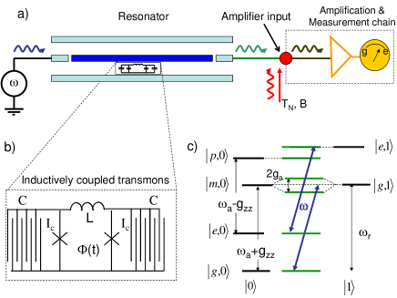
We exemplify hereafter this method with a diamond-shape artificial atom consisting of two transmons coupled by a large inductance. The system under study here is pictured in Fig.1, in which the resonator is schematized by a coplanar wave guide resonator, but our result can be applied to 3D cavities or lumped element resonators. The Josephson energy and the charging energy , with and the critical current and the capacitance per junction, are fixed to verify the typical ratio of the transmons limiting the decoherence effects Koch_PRA2007 . Such devices can be described by an anharmonic oscillator with two degrees of freedom. Its quantum description is the same than the one performed in Ref.Lecocq_PRL2011 for a dc SQUID in the particular case of zero-current bias or in Ref.Hu_PRB2011 ; Neumeier_arXiv2012 for two transmons coupled by a SQUID. It gives rise to two orthogonal modes, the symmetric and antisymmetric modeLecocq_PRL2011 . When the anharmonicity is strong enough, we can consider just the first two levels of the two modes. The system is then reduced to two coupled two-level systems. The two first quantum states of the symmetric mode, and , provide the logical qubit . The second two level system corresponds to the two first quantum states of the antisymmetric mode, and it will be used as an ancilla for the quantum measurement. In the absence of coupling between the two modes, the transition frequencies of the qubit and ancilla are given by of and , respectively. Hereafter we restrict our study to the working point given by zero-flux bias which constitutes an optimal point for the artificial atom. The coupling between the two systems is reduced to a longitudinal interaction term with a strength given by Lecocq_PRL2012 where with the SQUID inductance. This term can be viewed as an analogue of a cross-Kerr term between the two quantum systems, leading to a conditional energy transition of the ancilla which depends on the quantum state of the qubit and . The respective frequencies of the transitions and are and . The artificial atom inside a coplanar resonator is described by the following Hamiltonian, written in the rotating wave approximation:
| (1) |
The first three terms describe the artificial atom and the fourth describes the resonator of frequency . In the following we choose the frequency condition between the resonator and the ancilla: . The last term couples the resonator and the ancilla when the artificial atom is localized at the center of the resonator. Indeed, at this particular place, the quantum fluctuation of the flux is maximal and the voltage fluctuations are reduced to zero. Because of zero-flux bias working point, the qubit is not affected by flux fluctuations, leading to zero-coupling between the resonator and the qubit. This way, commutes with the Hamiltonian of the system, ensuring the non-destructive character of the measurement whatever the number of photons in the resonator.
To describe the transmission properties of the cavity as a function of the qubit state, we write a closed set of differential equations from Eq. (1) describing the time evolution of the system operators in the Heisenberg picture. These are deduced from input-output equations established in the case of a transmitting cavity as in christoph . We define the external fields (injected microwave field), (reflected field), and (transmitted field) that lead to the usual input-output equations: and where is the resonator coupling to external transmission line modes. As we consider an overcoupled cavity, we neglect the internal losses of the resonator and thus entirely defines the resonator linewidth. The qubit energy relaxation and dephasing times are assumed to be very long compared to the resonator relaxation time ( and ). The Heisenberg equations are written in the frame rotating at the frequency of the probe, yielding
| (2) |
where is the qubit state dependent shift, and the index defines the qubit state ( or ). As expected from a QND measurement, the evolution preserves . We are interested in the transmission properties of this system in the steady state regime established after a time much larger than . We adopt the semiclassical approach where the quantum correlations between atomic and field operators are neglected christoph . From now on we identify the operators with their average complex values, which could be measured in a homodyne experiment. The ratio can be written, in the steady state regime
| (3) |
where , and is the transmission of the empty resonator. We have introduced the drive power in units of photons per second , and the saturation power of the atom-cavity system reads
.
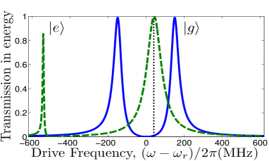
The essence of the protocol is pictured in Fig.2, in the linear regime when . In this regime the transmission is given by . If the qubit is in state , so that the ancilla qubit is resonant with the cavity mode and the transmission consists on two peaks located at with respect to the frequency of the resonator. If the qubit is in state , , inducing a dispersive coupling between the resonator and the ancilla provided that . The transmission essentially consists in a single peak slightly shifted by with respect to (see Fig. 2). Thus a change in the state of the qubit can now translate into a switch from dispersive to resonant coupling between the resonator and the ancilla. This is evidenced by a visible displacement in the transmission peaks by a quantity , which can be as high as , about two orders of magnitude higher than the usual dispersive ac-Stark shiftVijay_PRL2011 ; Riste_PRL2012 . This strong effect allows an increase in the linewidth of the resonator while keeping a high fidelity read-out. Working with a low Q cavity has important advantages. First, it drastically increases the total bandwidth of the circuit, and consequently the read-out speed. Moreover, for the same probe power, the average intracavity photon number is lower, preserving the lifetime and coherence time of the qubitBoissonneault_PRA2009 . The read-out is performed by the injection of a short microwave pulse of power at the frequency . Thus, the transmitted power depends on the state of the qubit, giving rise to two conditional output signals . When largely overcomes , one recovers the transmission pattern of the empty cavity, a signature of saturation christoph which limits the information on the qubit state.
We now introduce the model to optimize the measurement scheme. The performance of the read-out is usually quantified by two figures of merit, namely their fidelity and speed. Speed is high when the system can be measured frequently, the delay between two measurements being inferiorly bounded by their typical correlation time . is related to the inertia of the circuit, since the resonator imposes . Fidelity and correlation time depend on two independent parameters to optimize. First, the resonator linewidth should be narrow enough to give a large contrast between the two transmission patterns (), while large enough to allow a large transmitted signal and therefore high speed qubit read-out for a given photon number inside the resonator. In the same way, the driving power should be sufficiently low to avoid the saturation of the ancilla , but high enough to have a large .
In a typical circuit QED experiment, microwave photons are amplified before being sent through a homodyne detection scheme and digitalized within a short time interval , which is usually equal to . For our purpose, we shall consider the field at the entrance of the amplifying chain. The chain is modeled by a perfect amplifier Bergeral_Nature2010 radiating at the input of the circuit a white thermal field of effective temperature . This noise temperature ranges from a few hundreds of mK for the recent generation of quantum limited devicesRoch_PRL2012 ; Johnson_PRL2012 , to K for commercial devices. The total noise power , in units of photons per second, is given by Johnson-Nyquist noiseJohnson&Nyquist_PR1928 , where is the bandwidth of the amplifier, imposing an additional lower band to the correlation time . Consequently, high speed measurements are obtained at the price of increased bandwidth and noise power .
Estimation of the read-out fidelity is based on the photon number distributions conditioned to the qubit , which we computed using the Glauber-Sudarshan P-representation Glauber1993 . In our case, this simply corresponds to the P-representation of a thermal field of temperature displaced by a coherent field of amplitude . Thus we can readily calculate the generating function MandelBook for the photon statistics, from which we extract the coefficients
| (4) |
where is the -th order Laguerre polynomial.
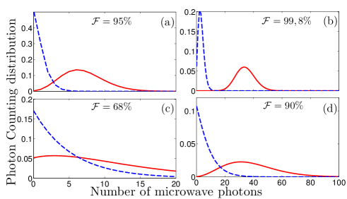
The histograms plotted in Fig. 3 clearly show how the amplification noise has a large effect on the statistics of the counts associated with each of the qubit states. As expected, the noise power increases with noise temperature (a vs. c and b vs. d), degrading the fidelity. By increasing the integration time, one can regain fidelity (a vs. b and c vs. d). As a matter of fact, it increases the signal, but it also allows one to operate with a lower bandwidth, reducing the noise power. We expect this protocol to yield a fidelity as high as with a commercial amplifier, within a typical time of ns. An integration as short as ns should be enough to reach with a state of the art amplifier with mK.
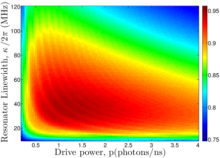
Fig. 4 shows optimization of the fidelity as a function of the resonator linewidth and probe power. The digitization time ns has been chosen, compatible with a bandwidth MHz. A fidelity can be reached with a resonator linewidth MHz and very small pumping power, corresponding to photons. This fidelity corresponds to up to date results obtained in the dispersive measurement scheme with the same amplifier Johnson_PRL2012 ; Vijay_PRL2011 , but allows a much faster acquisition time. Indeed, in dispersive based read-out schemes the dynamics is slow because of the inertia imposed by the resonator of linewidth MHz, inducing a typical correlation time of ns. With our scheme, using a low temperature amplifier allows a drastic increase in the bandwidth and read-out speed. This enables a projective measurement of the qubit to be performed on a timescale much shorter than the recently measured relaxation time, Paik_PRL2011 . This scheme opens the path to the observation of quantum jumps in circuit QED with a very high temporal resolution, comparable to the performances achieved in recent experiments performed with Rydberg atoms Gleyzes2007 , where the system is typically measured times before undergoing a quantum jump.
In conclusion we propose a new read-out scheme based on a superconducting diamond-shape artificial atom which contains a logical qubit strongly coupled to an ancilla qubit by a cross-Kerr term. We predict fast high-fidelity QND read-out of the transmon qubit with a commercial amplifier. Using a quantum limited amplifier, ns read-out time and fidelity are predicted. This original method overcomes the current read-out limitation of the superconducting qubits dispersively coupled to a resonator. In addition Purcell effect between the logical qubit and cavity is absent. As a side effect the intra-cavity population is minimal, for the optimal parameters, minimizing any adverse effect on the qubit coherence properties. This opens the possibility of monitoring quantum jumps of the qubit with very high temporal resolution Gleyzes2007 , of generating non-classical states Zhou2012 or implementating quantum error correction codes Chuang using closed feedback loops.
The authors gratefully thank N. Roch, P. Bertet, P. Milman , A. K. Feofanov and I. M. Pop for useful discussions. This work was supported by the European SOLID and the ANR-NFSC QuExSuperC projects, Nanosciences Foundation of Grenoble and CAPES.
References
- (1) A. Korotkov, Quant. Info. Proc. 8, 51 (2009).
- (2) J. Clarke et al., Nature (London) 453, 1031 (2008).
- (3) H. Paik et al, Phys. Rev. Lett. 107, 240501 (2011).
- (4) E. Lucero et al, Phys. Rev. Lett. 100, 247001 (2008).
- (5) A. Wallraff et al, Phys. Rev. Lett. 95, 060501(2005).
- (6) M. Boissonneault, et al, Phys. Rev. A 79, 013819 (2009).
- (7) I. Siddiqi, et al, Phys. Rev. B 73, 054510 (2006).
- (8) F. Mallet etal, Nature Phys. 5, 791 (2009).
- (9) M. D. Reed, et al, Phys. Rev. Lett. 105, 173601 (2010).
- (10) A. A. Clerk et al, Rev. Mod. Phys. 82, 1155 (2010).
- (11) N. Bergeral, et al, Nature 465, 64 (2010).
- (12) N. Roch et al, Phys. Rev. Lett. 108, 147701 (2012).
- (13) R. Vijay et al, Phys. Rev. Lett. 106, 110502 (2011).
- (14) D. Riste et al, Phys. Rev. Lett. 109, 050507 (2012).
- (15) J. E. Johnson et al, Phys. Rev. Lett. 109, 050506 (2012).
- (16) M. Hatridge, et al, Science 339, 178 (2013).
- (17) R. Vijay et al, Nature 490, 77 (2012).
- (18) B. G. U. Englert et al, Phys. Rev. B 81, 134514 (2010).
- (19) S. Kumar and D. DiVincenzo, Phys. Rev. B 82, 014512(2010).
- (20) J. Koch, et al, Phys. Rev. A 76, 042319 (2007).
- (21) F. Lecocq, et al, Phys. Rev. Lett. 107, 197002 (2011).
- (22) Y. Hu,et al, Phys. Rev. B 84, 012329 (2011).
- (23) L. Neumeier, et al, arXiv:1211.7215 (2012).
- (24) F. Lecocq, et al, Phys. Rev. Lett. 108, 107001 (2012).
- (25) A. Auffèves-Garnier et al, Phys. Rev. A 75, 053823 (2007).
- (26) L Mandel, E Wolf. Optical Coherence and Quantum Optics. (Cambridge University Press, 1995).
- (27) J.B. Johnson, Phys. Rev. 32, 97(1928);H. Nyquist, Phys. Rev. 32, 110(1928)
- (28) R. Glauber. Phys. Rev. 131, 2766 (1963).
- (29) S. Gleyzes et al, Nature 446, 05589 (2007).
- (30) X. Zhou et al, Phys. Rev. Lett. 108, 243602 (2012).
- (31) M.A. Nielsen and I.L. Chuang, ”Quantum Computation and Quantum Information”, Cambridge University Press, 2000.