Intermittent stick-slip dynamics during the peeling of an adhesive tape from a roller
Abstract
We study experimentally the fracture dynamics during the peeling at a constant velocity of a roller adhesive tape mounted on a freely rotating pulley. Thanks to a high speed camera, we measure, in an intermediate range of peeling velocities, high frequency oscillations between phases of slow and rapid propagation of the peeling fracture. This so-called stick-slip regime is well known as the consequence of a decreasing fracture energy of the adhesive in a certain range of peeling velocity coupled to the elasticity of the peeled tape. Simultaneously with stick-slip, we observe low frequency oscillations of the adhesive roller angular velocity which are the consequence of a pendular instability of the roller submitted to the peeling force. The stick-slip dynamics is shown to become intermittent due to these slow pendular oscillations which produce a quasi-static oscillation of the peeling angle while keeping constant the peeling fracture velocity (averaged over each stick-slip cycle). The observed correlation between the mean peeling angle and the stick-slip amplitude questions the validity of the usually admitted independence with the peeling angle of the fracture energy of adhesives.
pacs:
62.20.mm, 68.35.Np, 82.35.GhI Introduction
The stick-slip instability that can develop during the high speed peeling of adhesives, and which consists in strong oscillations between phases of slow and rapid propagation of the peeling fracture, constitutes a major problem in the polymer industry. The scratchy sound that anyone can experience when pulling on an adhesive tape, which is a trace of this instability, can indeed cause a level of acoustic noise that is simply unbearable in the industrial context. Another negative impact of stick-slip is the damage caused to the adhesive coating Ryschenkow1996 ; Yamazaki2006 when the instability occurs during the peeling of a temporary substrate layer before the adhesive is effectively used. It is for example a severe problem for hard disk drive (HDD) manufacturers as stick-slip will deteriorate the quality of the adhesive seal which can lead to HDD failure. These industrial concerns have recently conducted many patents on this issue to be deposited (e.g. Nonaka2009 ). Overall, adhesive stick-slip reduces industrial productivity and its current hard-to-predict nature hinders the development of new technical applications.
From a fundamental perspective, this unstable stick-slip crack growth is admitted to be the consequence of a decreasing fracture energy in a certain range of peeling fracture velocity . This anomalous drop of the fracture energy has been proposed to be related to structural transitions, from cohesive to interfacial failure Gent1969 , or between different interfacial failure modes Derail1997 . It has however also been proposed deGennes1996 that the rheological transition of adhesive materials —from soft to hard rubber or from rubber to glass— as a function of the strain rate could be, in the presence of confinement (which is the case for adhesive tapes), at the origin of a drop in the cohesive fracture energy. Overall, the stick-slip motion, resulting from this decreasing zone of fracture energy coupled to the compliance of the peeled tape or peeling machine, corresponds to an oscillation of the crack velocity between two (usually) very different values. There are several factors that may influence the peeling velocity range in which stick-slip effectively appears. For instance, the stick-slip velocity thresholds can show a dependence on the glass transition temperature of the adhesive Aubrey1980 ; Derail1997 , the thickness of the adhesive layer Gardon1963 ; Kim1989 , the substrate roughness Racich1975 and its viscoelastic properties Renvoise2007 . Remarkably, when stick-slip occurs, the details of its dynamics change with the imposed peeling velocity but also with the length of the tape submitted to the peeling load Barquins1986 and sometimes the stiffness of the loading machine Yamazaki2006 .
As proposed and verified experimentally by Kendall Kendall1975 , the fracture energy of a peeled adhesive tape does not depend on the peeling angle in the regular and slow (with respect to the stick-slip domain) peeling regime, which result is widely extrapolated to larger peeling velocities. An effect of the peeling angle on the velocity range for which stick-slip exists was nevertheless already reported in some early experiments Aubrey1969 , however in conditions where the length of the peeled tape was not constant but instead linearly increasing with time during the peeling.
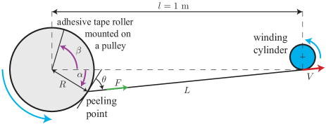
In this paper, we describe experiments of adhesive tape peeling from a freely rotating roller in which we aim at imposing the peeling velocity and the peeled tape length, defined as the distance between the peeling fracture front on the roller and a winding cylinder. Keeping these two parameters constant is indeed necessary to produce a well-defined stick-slip dynamics Barquins1986 . Thanks to a fast imaging camera coupled to image correlation velocimetry, we are able to extract the full dynamics of the peeling fracture velocity with respect to the substrate. In practice, we do not impose the peeled tape length but only the distance between the adhesive roller and the winding cylinder (Fig. 1). During an experiment at constant pulling velocity, superimposed on the stick-slip instability, we may observe a slow oscillation of the angular position at which the tape pulls on the roller. This slow dynamics causes the effective peeling angle (averaged over one stick-slip event) to oscillate with significant amplitude but in a quasistatic manner for the stick-slip. We report that the value of the effective peeling angle has a strong effect on the triggering and amplitude of the stick-slip instability, even tough the mean fracture velocity and peeled tape length remain constant or at least not significantly affected by the slow oscillations. This effect of the peeling angle on stick-slip cannot be simply understood by taking into account its influence on the work term of the elastic energy release rate as proposed by Kendall Kendall1975 . We suggest that the detailed features of any adhesive stick-slip motion should depend not only on the peeling velocity and peeled tape stiffness, but also strongly on the effective peeling angle.
II Experimental setup
We peel a roller adhesive tape, mounted on a freely rotating pulley, by winding up the peeled ribbon extremity on a cylinder at a constant linear velocity using a servo-controlled brushless motor (Fig. 1). The distance between the pulley and the winding cylinder is fixed to m. It is defined between the adhesive roller center and the point, assumed to be fixed, at which the peeled tape joins the winding spool. The adhesive tape used, 3M Scotch® 600, of the same kind as in Refs. Barquins1997 ; Cortet2007 , is made of a polyolefin blend backing (m thick) coated with a m layer of a synthetic acrylic adhesive. Each experiment consists in increasing the winding velocity from up to the target velocity at a rate of m s-2. Once the peeling velocity is reached, it is maintained constant to a precision better than during two seconds, before decelerating back to zero. We have varied the imposed velocity from to m s-1 in order to cover the whole range where stick-slip instability is observed for the considered adhesive tape and peeling geometry.
The local dynamics of the peeling fracture line, viewed as a point from the side, is imaged using a high speed camera (Photron Ultima 1024) at a rate of fps and a resolution of pixels. The field of view being approximately 2.5 cm wide, the resolution is about m/pixel. The recording of each movie is triggered once the peeling has reached a constant average velocity in order to obtain a stationary condition for the peeling experiment. Following the method presented in Cortet2007 , correlations between images of the movie, separated of a time (), allow to access:
-
•
the curvilinear position of the peeling point in the laboratory reference frame , where is the angular position of the peeling point (chosen positive in the clockwise direction, in Fig. 1) and is the roller radius (between 20 and 29 mm),
-
•
and, the curvilinear position of the adhesive roller , in the laboratory reference frame, where is the unwrapped angular position of the roller (chosen positive in the counterclockwise direction, in Fig. 1).
We are finally able to compute the curvilinear position of the peeling fracture point in the roller reference frame ( is chosen so that it increases when the peeling front advances)
| (1) |
We can then compute the peeling fracture velocity relative to the substrate
| (2) |
Here, the substrate simply consists in the backing of the adhesive tape remaining to peel.
The separation number between the images used for correlation is chosen such that the moving matter at the periphery of the roller displaces of about 5 pixels (m) between the two images. Since the correlation is subpixel interpolated, we reach a precision of about 1 pixelm on the displacement, i.e. 2%. We finally get the same precision of 2% on the average peeling point velocity over a timescale m, varying between 1.7 ms at the lowest imposed velocity and down to 0.1 ms at the largest imposed velocity.
III Equations of motion
The equation ruling the motion of the adhesive roller can be written as
| (3) |
where is the moment of inertia of the roller and the tensile force transmitted along the peeled tape. Here, the angle and are linked by the geometrical constraint
| (4) |
where m is the constant distance between the roller center and the point at which the tape joins the winding spool. An interesting limit case of Eq. (3) is then obtained De2004 when the roller radius is small compared to the distance , so that . In our experiments, it is almost the case, with , and the roller equation of motion (3) can be approximated by
| (3b) |
Then, assuming a uniform tensile strain in the peeled tape, the force transmitted to the roller is simply
| (5) |
where is the elongation of the tape of Young modulus , thickness and width . The assumption of a uniform peeled tape strain amounts to neglect transverse waves in the tape under tension. It is worth to note that these waves may however influence the high frequency stick-slip instability in some peeling regimes. In Eq. (5), the peeled tape length is not a constant (see Fig. 1) and varies with the angle according to
| (6) |
Experimentally, the observed instantaneous values of range between and at most. Such variations of induce peeled tape length variations of in our geometry. These very small variations of during the peeling experiments should have no significant impact on the velocity thresholds and the other features of the stick-slip instability Yamazaki2006 .
Finally, the following kinematical constraint on the peeled tape elongation applies
| (7) |
Note the sign change in the last term of Eq. (7) compared to Ref. De2004 due to the opposite orientation chosen for . Using the approximation , Eq. (1) and the integration over time of Eq. (7) give
| (7b) |
in which measures the unsteady part of the roller rotation. In Eq. (7b), and are constants corresponding to the values of and at for which by definition. Then, since the peeling crack length averaged over a long time simply equals to , one gets , where denotes the time average, which measures the mean level of deformation of the peeled tape during the experiment.
To close the system of equations describing the peeling experiments, one needs to model how the peeling fracture velocity is set. Such physical condition for peeling is usually expressed as a balance between the elastic energy release rate of the system and the fracture energy required to peel a unit surface such that
| (8) |
accounts for the energy cost of the dissipative processes near the fracture front during the fracture growth. In general, this fundamental quantity in fracture mechanics is characteristic of the type of material to fracture, of the fracture geometry and of the fracture velocity. For a given material and geometry, it is therefore classically considered to be a function of the fracture velocity only. In the context of adhesive peeling, is therefore also characteristic of the rheology of the adhesive material, of the backing and of the substrate. Finally, it is a priori also a function of the local geometry near the fracture front: the thickness of adhesive, the local peeling angle… However, most theoretical works on stick-slip adhesive peeling consider only the dependance of fracture energy on fracture velocity , except in some models which assume that is also dependent on the imposed velocity De2004 ; De2005 .
The elastic energy release rate corresponds to the amount of mechanical energy released by the growth of the fracture by a unit surface. This quantity, which is geometry dependent, both takes into account the work done by the operator and the changes in the recoverable energy stored in material strains. The following expression is traditionally used for the peeling fracture geometry Kendall1975 ; De2004
| (9) |
This is a very good approximation for most adhesive tapes and peeling geometries, except when the peeled tape stretching energy cannot be neglected for very small peeling angles Kendall1975 or when its curvature elasticity has to be taken into account Kinloch1994 especially for very short peeled tape length.
It is usually assumed that in the fracture propagation equation (8), the effect of peeling angle is fully taken into account by its appearance in the energy release rate (9). In other words, it is usually considered that itself does not depend on . Consequently, the velocity range in which stick-slip appears is expected to be independent of the peeling angle and to be set mainly by the region where has a negative slope, with some limitations due to an influence of the peeled tape stiffness Yamazaki2006 .
Altogether, we can identify three independent degrees of freedom (for example , and ) related to each other by the system of Eqs. (2-9) involving three differential equations: (3), (7) and (8). An interesting exact solution is the steady state, or fixed-point, solution corresponding to a regular peeling and given by
| (10) | ||||
IV Results
IV.1 Basic Stick-Slip features
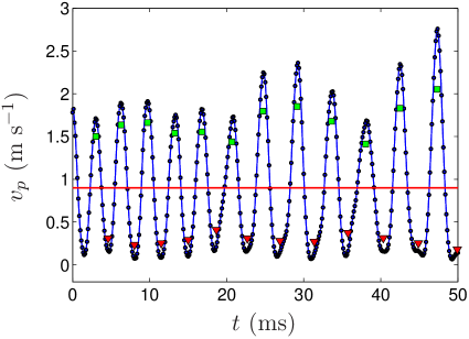
In Fig. 2, we plot a typical signal of peeling fracture velocity for an imposed peeling velocity m s-1. The observed large and oscillating fluctuations of are the characteristic signature of the stick-slip motion. Note that the amplitude of these oscillations is roughly as large as the mean peeling velocity. In particular, the peeling experiences an almost complete arrest with a very low fracture velocity (here, fluctuating between m s and m s) once every stick-slip cycle. The period of these oscillations is quite stable during an experiment (here, ms for m s-1).
Now considering all the experiments, over the whole range of peeling velocities m s-1 for which we observe stick-slip instability, the stick-slip oscillations period (averaged over all the stick-slip events for each experiment) is very stable, in the range ms. This result is in contrast with the data reported in Barquins1986 ; Maugis1988 for a different adhesive roller tape (3M Scotch® 602) also peeled at constant velocity. In Barquins1986 ; Maugis1988 , the stick-slip period was extracted from torque time series provided by the winding motor and was indeed shown to be proportional to and approximatively proportional to the inverse of over the whole range of instable peeling velocities (which was m s-1). The linearity of the stick-slip period with reported in Barquins1986 agrees with a model where the limit of stability of the stick phase, before the system jumps into the slip phase, corresponds to the reach of a constant threshold in strain or stress in the peeled ribbon. Indeed, during the stick phase the peeled tape strain almost linearly increases with time as . An important assumption of the model developed in Barquins1986 ; Maugis1988 is that the slip phase duration is negligible compared to the stick phase one. However, in these works, this assumption remained untested since the torque measurements did not allow a direct access to the peeling fracture dynamics contrary to our measurements. As can be seen in Fig. 2, the assumption of a negligible slip phase duration is obviously far from being true in our experiments which could explain why this model fails here and also suggests that we are not investigating a comparable stick-slip regime.
In our experiments, as a consequence of the constancy of the mean stick-slip cycle duration , the mean amplitude of the fracture propagation during stick-slip cycles increases almost proportionally to the peeling velocity according to . It is however remarkable to note that the dispersion inside a given experiment of the stick-slip cycles amplitude and period is increasing significantly from about 5 to 40% with the imposed velocity going from to m s-1. We will see in the following that this increasing dispersion is the trace of the growth with of low frequency oscillations of the mean peeling angle (averaged over one stick-slip event) which induce intermittencies in the stick-slip instability.
From the signal of instantaneous peeling velocity, we actually search for all the moments at which the sign of changes. When goes from positive to negative, it defines the beginning of a stick event and when it goes from negative to positive, it defines the beginning of a slip event. We then compute the mean stick and slip velocities as the average value of the velocity during the phases where (stick) and (slip). Finally, only the events during which is successively smaller than and larger than are considered as true stick-slip events. This allows to avoid measurement noise and small velocity fluctuations to be taken into account as stick-slip events during periods where no stick-slip is present. These stick and slip velocities are reported in Fig. 2 as triangle and square symbols respectively. We observe that the stick and slip mean velocities are fluctuating in time during a peeling experiment at constant velocity . This is probably mainly because of heterogeneities in the adhesion properties of the peeled tape and also maybe, to a lesser extent, because of the fluctuations of the imposed velocity.
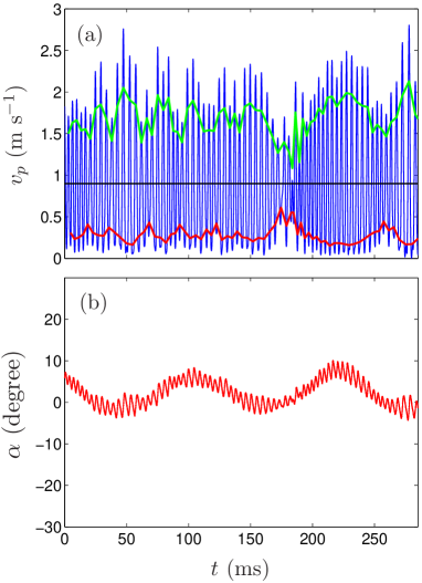
At the lower peeling velocities belonging to the instable interval, the stick and slip velocities are however relatively stable throughout the peeling cycles during an experiment as can be seen in Fig. 3(a) (same experiment at m s-1 as in Fig. 2). We nevertheless observe in this figure at time ms that the stick-slip amplitude decreases abruptly and temporarily during three stick-slip cycles. We believe such “accident” may be related to rare large scale defects in the adhesion of the commercial tape.
IV.2 Stick-Slip intermittencies and roller pendular oscillations
Remarkably, as the average peeling velocity is increased, we observe that the stick-slip dynamics becomes intermittent, alternating regularly between periods of time with fully-developed stick-slip cycles and periods of time without or at least with strongly attenuated stick-slip amplitude. A typical example of such intermittencies is shown in Fig. 4(a) where a period of about 140 ms ( Hz) can be seen. Comparing these data with the instantaneous angular position of the peeling point in the laboratory in Fig. 4(b), we see that the intermittent stick-slip behavior is strongly correlated with low frequency variations of this angle, whereas high frequency variations of (at about Hz) are directly correlated to the stick-slip motion.
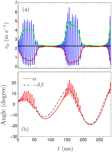
The slow oscillations of the angular peeling position are the direct consequence of a low frequency pendulum-like motion of the adhesive roller, in addition to its mean rotation at a rate . Indeed, as can be seen in Fig. 4(b), the angle , which measures the unsteady part of the roller rotation, matches rather well the low frequency oscillations of when smoothing over the fast stick-slip oscillations. This observation, , where stands for the average over a stick-slip cycle, can be understood in the following way. Experimentally, we observe that the mean (averaged over a stick-slip cycle) fracture velocity is always equal to the imposed peeling velocity to better than . Therefore, to a good approximation, we have . Finally, using the first equality in Eq. (7b), this shows that as is indeed verified in Fig. 4(b). Furthermore, averaging Eq. (3b) over a stick-slip cycle and using , we get
| (11) |
which predicts pendular oscillations of the unsteady part of the roller rotation at a frequency close to for small amplitudes of .
To check this interpretation of the pendular oscillations, we have made some measurements of the mean peeling force , time averaged over the whole constant velocity peeling experiment. This is done with a force gage (Interface® SML-5), aligned with the direction , and placed between the adhesive roller pulley and its mechanical support. In table 1, we compare the frequency of the slow oscillations with the characteristic frequency replacing by its temporal average value. Although this framework is only approximate, we find a rather good agreement between the direct measurement of the period and the theoretical prediction . We conclude that the low frequency dynamics develops due to the interplay between the inertia of the roller and the moment applied to the roller by the peeling force as already suggested in Cortet2007 .
| (m.s-1) | (N) | ||
|---|---|---|---|
| 0.36 0.01 | 1.71 0.07 | 0.109 0.005 | 0.092 0.002 |
| 0.50 0.01 | 1.40 0.06 | 0.115 0.005 | 0.102 0.002 |
| 0.72 0.02 | 1.18 0.05 | 0.118 0.005 | 0.111 0.002 |
| 1.53 0.03 | 0.91 0.04 | 0.130 0.005 | 0.126 0.003 |
In the two previous paragraphs, we have shown that the slow pendular oscillations of the adhesive roller are independent of the physics of the adhesive fracture propagation. We have indeed verified that the roller rotation is unsensitive to the high frequency stick-slip oscillations of and because of the roller inertia. Consequently, we feel entitled in the following to consider the slowly oscillating mean peeling angle as an effective control parameter for the fracture problem (i.e. Eq. (8)), which is quasi-statically varying.
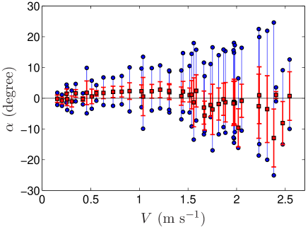
In order to quantify the slow oscillations of the peeling point angular position for various imposed velocity , we plot as a function of the mean angle during each experiment and the corresponding standard deviation of its oscillations as errorbars (Fig. 5). We also report the maximum and minimum angle reached during each experiment. We can note the regular increase of the oscillation amplitude of from up to as the imposed velocity increases in the instable range, whereas its mean value is quite stable in the range . Since the effective peeling angle verifies , it has a mean value always close to , corresponding to the steady state solution (10), and variations up to around the mean at large peeling velocities.
In Fig. 4, we see that large amplitude stick-slip occurs mostly for the larger and positive values of (i.e., ) whereas for negative values (i.e., ), stick-slip almost disappears. Such straightforward correlation is however a simplistic picture since it can also be noted that there is some hysteresis in the angle at which stick-slip appears and disappears. Guesses could be that the hysteresis is due to a delayed response of the peeling instability when the angle changes, which would corresponds to a value of the stick-slip instability growth rate comparable to the pendular oscillations frequency. More generally, this hysteresis may reveal dynamical effects related to . At low peeling velocity (Fig. 3(b)), low frequency oscillations of the peeling point angle do actually already exist but, as we have seen, are of smaller amplitude. They moreover apparently do not correlate with small stick-slip amplitude modulations. This suggests that the slow oscillations of must overtake a certain amplitude to trigger a significant time modulation of the stick-slip amplitude.
IV.3 Stick and Slip velocities, and correlation with peeling angle
In Fig. 6(a), we plot the average (over all the events in each experiment) stick and slip velocities as a function of the imposed peeling velocity . For the lower peeling velocities, we have plotted which means that the peeling is regular without observation of stick-slip events. The stick-slip actually initiates at a peeling velocity threshold of m s-1 with average stick and slip velocities starting to deviate from the imposed peeling velocity (continuous line). This threshold corresponds very well to the value measured for the same roller adhesive tape peeled by falling loads Cortet2007 . The stick and slip velocities increase gradually for varying from up to m s-1 for which value they collapse on the average velocity . The measured disappearance threshold for stick-slip at large velocities, m s-1, is also compatible with the previously measured value in peeling experiments by falling loads where it was about m s-1.
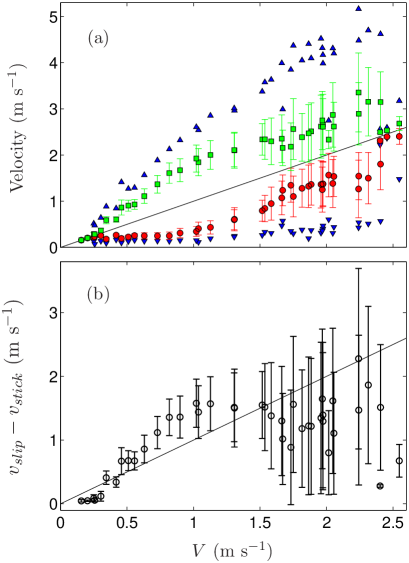
In Fig. 6(a), the data are accompanied with their corresponding statistical standard deviation inside each experiment. These standard deviations are quite low ( to ) from to m s-1 which means that the corresponding stick-slip features are quite stable during a given experiment. For average velocities larger than m s-1 and up to the disappearance of the stick-slip at m s-1, we observe larger standard deviations ( to ) for the stick and slip velocities. This increase is obviously the trace of the stick-slip intermittencies that lead to alternate periods of strong and weak stick-slip oscillations.
Finally, in Fig. 6(a), we also plot the maximum slip and minimum stick velocities measured during each experiment. We see that as the peeling becomes more and more intermittent with the increasing peeling velocity , the extreme values of the stick and slip velocities are further and further away from the average ones which reveals the amplitude of the stick-slip modulations. Focusing on the two experiments at imposed velocity m s-1, we can observe one experiment with a developed stick-slip and one experiment with almost no remaining stick-slip with mean stick and slip velocities about only smaller and larger than respectively. These observations reveal the unprecise definition of the stick-slip disappearance threshold which is an intrinsic feature of adhesive stick-slip, amplified in the present case by the slow oscillations of the peeling angle. Regarding the mean velocities, the last two data points, at and m s-1, show an almost complete absence of stick-slip. On the contrary, we see that the maximum slip and minimum stick velocities are very close to for m s-1 but quite far anew for the experiment at m s-1: in the last case, this is simply the trace of very marginal stick-slip events existing only during short phases of the pendular oscillations where the angle is large.
To study these intermittencies in more details, in Fig. 6(b), we plot as a function of the imposed velocity the quantity averaged over all stick-slip cycles in each experiment. We see that the mean velocity amplitude of stick-slip is first larger than the imposed velocity up to m s-1 before being overall lower and quite scattered as a consequence of the stick-slip intermittencies. Here, again the errorbars correspond to the standard deviation of the plotted statistical quantity. This data illustrates very well the strong increase of the explorated range of stick-slip amplitudes as the peeling velocity increases. One can indeed observe in Fig. 6(b) that the standard deviation of the stick-slip amplitude becomes almost as large as its mean value for m s-1 which is the trace of the strongly intermittent behavior.
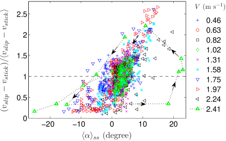
Finally, in order to quantify the correlations between the peeling point angular position and the amplitude of stick-slip, we introduce an order parameter defined as the difference between the slip and stick velocities for each stick-slip event, , normalized by its average over all the events at a given imposed velocity. Fig. 7 shows the evolution of this parameter as a function of the mean angular position of the peeling point for each stick-slip cycle during the experiments and for a wide selection of imposed velocity . We first see that the average operating point in each data series at a given imposed velocity , which is defined by , corresponds for a large majority of events to angles in the region . This observation is the trace of the fact that, without the parasitic pendular oscillations of the roller which generate the intermittencies, the stick-slip peeling would naturally proceed with a mean peeling angle in the range . Around this operating point , ), the statistics of the stick-slip events gather on a cloud which can be (roughly) modelled by
with a rapidly increasing function and a separation of the variables and . Here, is defined as the mean velocity contrast, , for a given stable peeling angle . These data confirm that the stick-slip instability increases dramatically in amplitude with and occurs preferentially when whereas it tends to disappear when . These results overall point out an important effect of the peeling angle (Fig. 1) on the stick-slip instability thresholds and amplitude.
Speaking more accurately, the order parameter dependence as a function of the angle does obviously not collapse perfectly on a master curve in Fig. 7. It actually shows an hysteresis that becomes stronger at large velocities (see the arrows indicating the time sequence of successive stick-slip events in the m s-1 experiment). As already mentioned, we attribute this hysteresis to a delay in the response of the peeling instability to a change in the experimental peeling angle or to the dynamical effects of . Nevertheless, this hysteresis is far beyond our current understanding of the adhesive stick-slip peeling. To the first order, we therefore believe that this overall dependance of the stick-slip amplitude with the local mean (over each stick-slip cycle) peeling angle reflects a general intrinsic dependance of the peeling fracture process with the peeling angle , which should be explored in peeling experiments at imposed mean angle .
V Discussion
Theoretically, the angle at which the peeling of an adhesive tape is performed is usually taken into account in the calculation of the elastic energy release rate through Eq. (9). If one further assumes that the fracture energy is independent of the peeling angle as suggested by Kendall’s experiments in the regular peeling regime, the velocity thresholds for the onset of stick-slip instability, related to the zone where is a decreasing function, should also be roughly independent of the effective peeling angle . In that case, there are consequently no clear reasons for stick-slip to be strongly dependent on the peeling angle at a given mean fracture velocity in the instable range of . The susceptibility of the stick-slip instability to the peeling angle that we report in this article therefore questions which are the correct dissipation mechanisms that should be taken into account in the fracture energy during the instable regime of the peeling.
The behavior we have observed in Fig. (4) resembles to some extent the dynamics predicted by some models (see for instance Fig. 4(b) in De2004 ). Here, the authors have assumed that the fracture energy is a function of both the local peeling velocity and the imposed velocity so that , which can be viewed as an ad hoc guess. In the roller geometry, this model sometimes predicts a stick-slip dynamics corresponding to high frequency oscillations of the angle superimposed to a lower frequency and larger amplitude variation. The authors explain that this behavior is obtained either when increasing peeling velocity for a given inertia of the roller or when increasing the roller inertia for a given peeling velocity. Thus, the intermittent appearance and disappearance of stick-slip observed in this model seems to be the consequence of a subtle balance between the effect of inertia of the roller and the effect of a fracture energy depending explicitly on both the pulling velocity and the fracture velocity .
Another possibility to understand the observed stick-slip dynamics would be that the fracture energy itself depends on the peeling angle so that . From static equilibrium considerations, it is clear that varying the angle of peeling will change the relative contribution of normal and shear load on the adhesive at the peeling front. Since it has been observed that shear can have an effect on the resistance of adhesives to rupture Amouroux2001 , one could think that it can also have an effect on the dependence of the fracture energy with velocity, contrary to the results of Kendall Kendall1975 . The onset of stick-slip instability would then naturally become dependent on the peeling angle.
At this point, it is not possible to conclude whether the intermittent stick-slip behavior observed in our experiments is due to inertial effects of the roller combined with a dependence of the fracture energy as proposed in De2004 , or if it is rather due to a direct dependence with the angle. Experiments performed in a different geometry, such as peeling from a flat surface at constant angle , would help distinguish between the two proposed mechanisms.
Acknowledgements.
This work has been supported by the French ANR through grant “STICKSLIP” No. 12-BS09-014-01.References
- (1) G. Ryschenkow and H. Arribart, J. Adhes. 58, 143 (1996).
- (2) Y. Yamazaki and A. Toda, Physica D 214, 120 (2006).
- (3) T. Nonaka, S. Inokuchi and O. Masahiro, US Patent-7534478 (2009).
- (4) A. Gent and R. Petrich, Proc. R. Soc. London A 310, 433 (1969).
- (5) C. Derail, A. Allal, G. Marin and P. Tordjeman, J. Adhesion 61, 123 (1997); 68, 203 (1998).
- (6) P.-G. de Gennes, Langmuir 12, 4497 (1996).
- (7) D. W. Aubrey and M. Sherriff, J. Polym. Sci., Part A: Polym. Chem. 18, 2597 (1980).
- (8) J. L. Gardon, J. Appl. Polym. Sci. 7, 625 (1963).
- (9) J. Kim, K. S. Kim and Y. H. Kim, J. Adhesion Sci. Technol. 3, 175 (1989).
- (10) J. L. Racich and J. A. Koutsky, J. Appl. Polym. Sci. 19, 1479 (1975).
- (11) J. Renvoise, D. Burlot, G. Marin and C. Derail, J. Adhesion 83, 403 (2007).
- (12) M. Barquins, B. Khandani and D. Maugis, C. R. Acad. Sci. Paris 303, 1517 (1986).
- (13) K. Kendall, J. Phys. D: Appl. Phys. 8, 1449 (1975).
- (14) D. W. Aubrey, G. N. Welding and T. Wong, J. Appl. Polym. Sci. 13, 2193 (1969).
- (15) M. Barquins and M. Ciccotti, Int. J. Adh. Adh. 17, 65 (1997).
- (16) P.-P. Cortet, M. Ciccotti and L. Vanel, J. Stat. Mech. P03005 (2007).
- (17) R. De, A. Maybhate and G. Ananthakrishna, Phys. Rev. E 70, 046223 (2004).
- (18) R. De and G. Ananthakrishna, Phys. Rev. E 71, 055201 (2005).
- (19) A. J. Kinloch, C. C.Lau and J. G. Williams, Int. J. Fracture 66, 4 (1994).
- (20) D. Maugis and M. Barquins, in Adhesion 12, edited by K. W. Allen (Elsevier ASP, London, 1988), p.205.
- (21) N. Amouroux, J. Petit and L. Leger, Langmuir 17, 6510 (2001).