Scalable universal holonomic quantum computation realized with an adiabatic quantum data bus and potential implementation using superconducting flux qubits
Abstract
In this paper we examine the use of an adiabatic quantum data transfer protocol to build a universal quantum computer. Single qubit gates are realized by using a bus protocol to transfer qubits of information down a spin chain with a unitary twist. This twist arises from altered couplings on the chain corresponding to unitary rotations performed on one region of the chain. We show how a controlled NOT gate can be realized by using a control qubit with Ising type coupling. The method discussed here can be extended to non-adiabatic quantum bus protocols. We also examine the potential of realizing such a quantum computer by using superconducting flux qubits.
Introduction
It has recently been demonstrated how an open-ended antiferromagnetic Heisenberg spin chain can be used as an adiabatic quantum data bus Chancellor2012 (see Sec VI.1 for a brief review). This data bus takes advantage of antiferromagnetic couplings to transfer qubits of information adiabatically. First a single qubit, encoded in a single spin is joined to an even length Heisenberg spin chain slowly enough such that the adiabatic theorem applies. Then a single spin on the other end of the chain is separated, again slowly enough for the adiabatic theorem to apply. As long as the interactions between the spins on the chain are predominately antiferromagnetic, the qubit will be successfully transferred from one end of the chain to the other. This protocol is illustrated in Fig. 1. Antiferromagnetic spin clusters have been studied for there potential usefulness in quantum computing in other contexts, for example in Refs. Meier2003 ; Benjamin2003 .
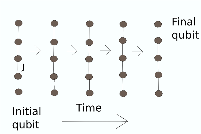
This paper demonstrates how by applying particular unitary operations to spin chains for single qubit gates, and by using a specific spin network for a CNOT gate, one can achieve universal holonomic quantum computation. This method uses open-loop holonomies, meaning that the Hamiltonian is not necessarily returned to the same state after the adiabatic process. The methods used here can also be extended to non-adiabatic implementations of geometrical quantum computing.
Holonomic quantum computation (HQC) was conceived and shown to be universal by Zanardi and Rasetti Zanardi1999 and was formulated in terms of a non-abelian Berry phase. HQC is considered to be an appealing method for achieving fault tolerant quantum computing because of its geometrical nature and because it can be implemented adiabatically, and therefore has all of the advantages of adiabatic quantum computation Pachos2001 . Although many implementations of holonomic and geometric quantum computation are adiabatic, there are examples which are not Xu(2012) ; Mousolou2012 .
Other proposed architectures for holonomic quantum computation use a variety of architectures, including superconducting systems with Josephson junctions Faoro2003 . Further examples propose using quantum dots Solinas2003 ; Mousolou2012 . Single molecule magnets have been another system of interest Mousolou2012 . A recent proposal has also been made for using Holonomies which involve attaching and removing a spin from a spin 1 chainRenes2011 . This architecture, although it looks superficially very similar to ours, performs computations locally, at the site of the spin rather than by transport as ours does. Ref. Renes2011 also proposes an implementation on ultracold polar molecules. Another interesting proposal involves using a quantum wire with a twisted cluster state HamiltonianBacon2012 . This proposal is similar to ours, but implements the twist in a fundamentally different way.
Most other approaches to HQC involve building a system, and explicitly calculating the holonomies caused by various manipulations of the system. In our proposal we start with a process which has a trivial Berry phase111Here I mean trivial if the adiabatic bus protocol were performed twice, once to transport the spin to another site and once to return it to its original location.. Real space twists are then performed on the spin chain used in this process. Unlike most examples of HQC, all results can be derived without explicitly considering the curvature of the underlying manifold of states, all single qubit gates result from the same underlying Hamiltonian with basis rotations applied to it.
In principle this idea could be used for more traditional, closed-loop holonomic quantum computation by twisting a spin chain used to transport the qubit adiabatically slowly, performing an adiabatic transport protocol, untwisting the chain adiabatically slowly, and performing the transport protocol in reverse to return to the initial Hamiltonian. The net result of this process would be to perform a rotation on the initial spin which the qubit is encoded and return the spin chain to its initial state. In this case spin rotation would be achieved by a non-abelian Berry phase acquired via transport on a closed adiabatic loop in parameter space, and would therefore be a closed-loop holonomic gate. Such a process involves unnecessarily many steps however, so it is more convenient to think of this process in terms of the framework of open-loop holonomic quantum computation.
The mathematical differences of this approach from others affords us the advantage that the spectrum of the underlying Hamiltonian is the same for all twists, meaning that, by construction, all single qubit gates can be implemented in a way which requires the same annealing time to reach a given accuracy. This architecture has the advantage that the only operation it ever requires to be adiabatically performed is the joining or removal of a spin from a chain or cluster. The nature of the twists used here also means that a non-adiabatic transport protocol could be used instead, and universal computation would still be achieved.
This paper also outlines an implementation of the necessary components of this design using superconducting flux qubits. Superconducting flux qubits are a popular architecture for implementing scalable adiabatic quantum computing Johnson2011 ; Harris2010-1 ; Perdomo2008 ; vanderPloeg2006 ; Harris2010-2 , and therefore are a natural choice for designing a scalable holonomic quantum computer. An additional advantage of the use of superconducting flux qubits is that the designs tend to have spatially extended qubits and a high degree of connectivityHarris2010-2 . The large spatial extent of the qubits means that a design could be implemented in which a qubit would only need to be transferred across a small number of spins to be moved from one location in a computer to any other arbitrary location. For this reason it is only necessary that the transport protocol be efficient for short chains, as has already been demonstrated in Chancellor2012 , rather than in the thermodynamic limit.
There has been recent experimental work involving quantum annealing to degenerate ground state manifolds using currently available superconducting flux qubit hardwareBoixo2012 . In this paper it was demonstrated experimentally that signatures of quantum behaviors can be observed in the final state within a degenerate ground state manifold. This provides an indication that a ground state manifold can be produced accurately enough on current hardware that quantum effects dominate over classical effects and design inaccuracies. Although the architecture proposed here cannot be implemented on the hardware used in Boixo2012 , this experiment does provide proof of principle for the use of degenerate manifolds in superconducting flux qubit systems.
While it is not the main focus of this paper, we would also like to point out that there are other potential methods of implementing this architecture. One example of such an implementation would be to use a coupled cavities scheme similar to the one explored in Chen2010 . For such an implementation long spin chains may be required, and as a result properties in the thermodynamic limit may be important. For such an implementation, the architecture given in this paper could easily be generalized to a J1-J2 spin chain with which is know to be gaped in the thermodynamic limitChitra1995 . In this case, another option would be to implement the architecture non-adiabatically using the methods described in Banchi2010 ; Banchi2011 ; Apollaro2012 ; Banchi2011-2 .
I Single Q-bit Gates
I.1 The Twisted Spin Chain
Consider initially an antiferromagnetic Heisenberg spin chain. It has been shown that such a chain can act as a quantum data bus, both adiabaticallyChancellor2012 and by using the dynamics of its excitations Banchi2010 ; Banchi2011 ; Apollaro2012 ; Banchi2011-2 . The initial Hamiltonian is given by
| (1) |
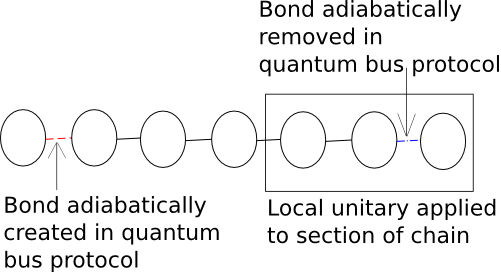
Now imagine that one inserts a twist into the spin chain by applying a local unitary transformation of the form on spins222Note that this twist can be performed on any bond in the chain, including one of the bonds, including the bonds which are created or destroyed in the adiabatic bus protocol. A minimum of three spins is required for a gate to be implemented adiabatically because of the requirement of an odd overall chain length by the adiabatic quantum bus protocol. If a different transport protocol were used, a gate could be implemented with only 2 spins. , where are all mutually orthogonal to each other. This yields a new Hamiltonian of the form
| (2) |
Such a twist does not effect the spectrum of the Hamiltonian, and therefore the dynamics of the adiabatic quantum bus protocol, or other quantum bus protocols which may make use of the unitary dynamics of the Hamiltonian. It is important to note, however, that after transfer across the chain, the spin will be rotated into the basis. As we will demonstrate later, transfer through this twisted spin chain can perform any desired unitary rotation on the qubit being transferred, and thus can be used to implement any single qubit gate, see Fig. 2.
One should note that while in this example we consider a simple Heisenberg spin chain, gates can be implemented in this way on an XYZ spin chain or a J1-J2 spin chain, or other sufficiently complex quantum spin Hamiltonians 333This argument breaks down in general if one considers cases where there is not coupling in all three spin directions, for example in an XY model.. Figuring out which twist to use to perform a given gate can be done easily and will be illustrated in the next section.
I.2 Example: Implementing a Hadamard Gate
The local twist to implement the Hadamard gate is , and . This twist can be calculated without difficulty, for details see Sec. VI.2.
One can therefore conclude that the Hadamard gate can be implemented by performing the quantum bus protocol on the Hamiltonian
| (3) |
I.3 Other Single Qubit Gates
One can perform similar twists to implement any given single qubit gate. The calculation to find in Eq. 2 for other gates can be performed in the same way as the one in the previous section for the Hadamard. Table 1 shows how to implement single qubit gates. These gates are sufficient to perform an arbitrary unitary operation on a single spin. It is shown in Nielsen and Chuang that any unitary rotation can be approximated to arbitrary precision with the gates given in table 1. We have already shown how to build an adiabatic quantum bus to move qubit states to arbitrary locations in the system. Next we discuss that a CNOT gate can be implemented under this architecture. Then we have demonstrated a universal quantum computer.
| Gate Name | Matrix | |||
|---|---|---|---|---|
| Hadamard | ||||
| ) | ) | |||
| phase | ||||
| NOT444This gate is needed for the construction of the CNOT |
II Implementation of the Controlled NOT Gate
II.1 CNOT design
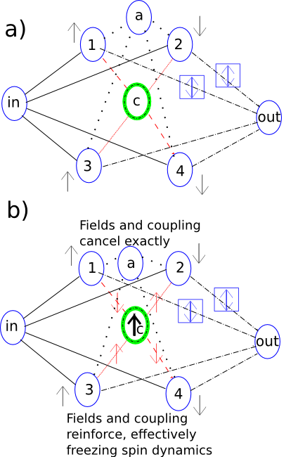
Let us now turn our attention to the implementation of a controlled NOT (CNOT) using an adiabatic quantum bus protocol. In Fig. 3a) we show a design for such a gate. The time dependent Hamiltonian for this gate is
| (4) |
Here “in” refers to the spin which is the input spin, where the target qubit is initially encoded; “out” refers to the spin to which the target qubit is transferred to, “c” refers to the control qubit, “a” to an ancilla to make the number of intermediate spins odd. The other 4 spins are assigned numbers 1-4. refers to a NOT twist being performed on these Pauli matrices, see Tab. 1. This gate operates by having 2 channels through which a qubit of information can pass. One channel, consisting of spins 3 and 4, allows the information to pass through the gate unaltered, while another channel, consisting of spins 1 and 2 performs a twist on the qubit as it travels though the gate. The control spin c controls though which channel the information travels. The control spin is connected with Ising type coupling to spins 1-4 in such a way that when the control spin is up the external field on spins 1 and 2 cancels with the effect of the Ising bond with spin c because , and the information can easily pass though these spins. On the other hand . So spins 3 and 4 both have an effective magnetic field of 2h. For sufficiently large h these spins are frozen in the direction of the field and will therefore not be able to transport any information. As we show in Fig. 3b) the net effect is that information all travels though spins 1 and 2, and therefore a NOT twist is performed. In the case where the spin c is in the down direction, information will instead be allowed to travel though spins 3 and 4 and blocked on spins 1 and 2. Therefore in that case the gate acts trivially on the qubit.
Any state of the control spin c can be expressed as where a and b are complex numbers. With an arbitrary input state we have before the gate . After the gate is performed, the final state becomes . From these general states we see that
| (5) |
which is the definition of a controlled NOT gate Nielsen and Chuang .
| Symbol | Meaning |
|---|---|
| spin control spin | |
| spin working spin | |
| initial AF Heisenberg bond (weak) | |
| final AF Heisenberg bond (weak) | |
| fixed AF Heisenberg bond (weak) | |
| twist to perform NOT operation | |
| fixed F Ising bond (strong) | |
| fixed AF Ising bond (strong) | |
| fixed “up” magnetic field (strong) | |
| fixed “down” magnetic field (strong) |
II.2 Performance of Controlled NOT Gate
We need to test how this design for a CNOT gate performs because we cannot rely on previous work to show that the qubit is actually transferred accurately. The two free parameters in Eq. 4 are the strength of the Ising bonds and the fields which we denote by h, and the time for the protocol to be performed,
We now examine whether this Hamiltonian actually implements a CNOT gate effectively for reasonable values of h and . To test this we need to answer 2 questions. Firstly, is the system close enough to the adiabatic limit for reasonable values of ? Secondly, is the desired effect of shutting off one possible path for the information achieved for reasonable values of h? To answer these questions, we examine the overlap of the final output state (final state of the “out” qubit in Fig. 3) with the expected output state from a controlled NOT gate (Fig.4). Note that because the case where a NOT gate is performed, and the case where the gate acts trivially are related by a simple unitary transformation on the Hamiltonian, acceptable performance in one of these cases implies acceptable performance in the other. Averaging over different initial states is therefore unnecessary as it would yield the exact same result as any particular choice of control and input states.
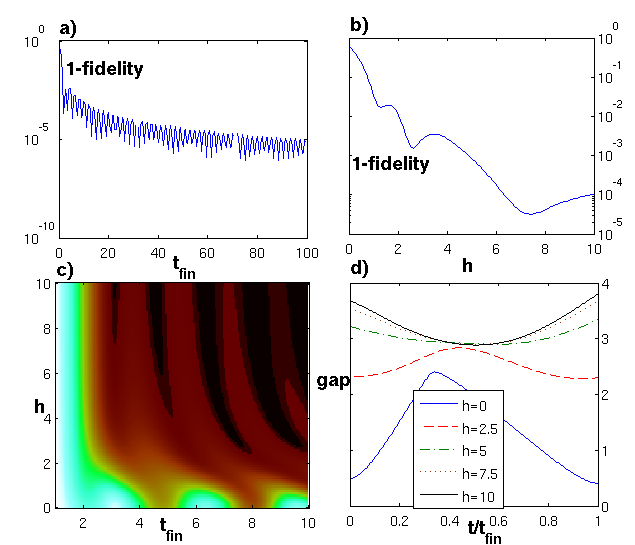
Fig. 4 demonstrates the effectiveness of this gate. Fig. 4 a) shows that for a moderate field and Ising bond strength the gate can be made to perform well as long as the annealing time is sufficient. This figure also shows that the gate can continually be made more effective by running it longer without having to raise h. The oscillations in the fidelity are related to the time scale of small excitations produced during the annealing process. In many applications one may have enough control over that the annealing time can be chosen in a way that the process lies near one of the local minima of error shown in Fig. 4 a).
Fig. 4 b) shows the effect of h on fidelity for an annealing time of 10 (in units of inverse Heisenberg couplings). In this figure one can see that increasing h is ineffective at improving performance above a certain value. This indicates that at this point the field is already effectively completely blocking one path that the information transport can take. Fig. 4 c) shows the combined effects of h and on the output polarization. It is consistent with the conclusions we have reached from a) and b). Finally, Fig. 4 d) shows that the system gap remains quite large throughout the process. It also demonstrates that beyond a certain value of h the gap does not increase significantly with changing h, which is consistent with the picture of one path being completely closed to information transfer. It is interesting to note that increasing h increases the gap throughout the process.
III Implementation Using Superconducting Flux Qubits
To build an implementation of this holonomic architecture based on superconducting flux qubits one needs to design circuits that implement Heisenberg spins and the appropriate gate couplings between spins. Fortunately significant work has already been done, for example in Refs. Johnson2011 ; Harris2010-1 ; Perdomo2008 ; vanderPloeg2006 ; Harris2010-2 , towards the design of couplers for superconducting flux qubits. However since the previously discussed schemes were based on Ising spin systems, we still need to establish a method for designing circuits which emulate Heisenberg spins. It is interesting to point out that this computational architecture works with the limited connectivity of the designs proposed in Refs. Johnson2011 ; Harris2010-1 ; Perdomo2008 ; vanderPloeg2006 ; Harris2010-2 . Specifically the CNOT gate we have proposed fits in a single 2x4 chimera lattice cell like the one used in Ref. Harris2010-2 .
III.1 Flux Qubit Motivation:
It has been shown in Harris2010-1 that a qubit which behaves like an Ising spin can be constructed from a Hamiltonian of the form
| (6) |
where the applied fluxes act as effective magnetic fields, altering the shape of a potential well for the system in a way that mimics a spin constrained to move in a plane. The constants simply act to scale the effect of the flux. To construct a Heisenberg qubit one needs to add a third direction, leading to a Hamiltonian of the form
| (7) |
Such a Hamiltonian would allow the shape of the potential well to be changed along 3 directions and would therefore mimic a Heisenberg spin rather than an Ising spin. Previously proposed designs also only couple qubits along one direction. If a new type of coupler were added to the currently implemented circuits which couple the spins in the y direction in addition the z direction, then an XY model could be implemented. To implement an XYZ Heisenberg model, one needs to both design qubits which are not constrained to lie in a plane and build 3 types of couplers, one for each direction in space.
IV Flux Qubit Design:
First consider a CCJJ (Compound-Compound Josephson Junction) circuit as defined in Harris2010-1 .
The effective Hamiltonian of this circuit is given by Harris2010-1
| (8) |
where . Note that there are more indeces than in Harris2010-1 because we do not have the condition that or . The first two terms of the Hamiltonian in Eq.8 are not important for what we are trying to demonstrate here Harris2010-1 . The definition of all of these terms can be found in Eq. B4b-f in Harris2010-1 , and in Sec. VI.3 of this paper.
Let us make the simplifying assumption that all of the critical currents are equal for all junctions. In practice there is variability in junction fabrication, but this error can be compensated by building a CCCJJ device (see Fig. 5). Let us also assume that our circuit is designed in such a way that we can inductively couple the left and right loop to each other very strongly such that and . These assumptions cause the equations to simplify greatly (see Sec. VI.3), yielding
| (9) |
| (10) |
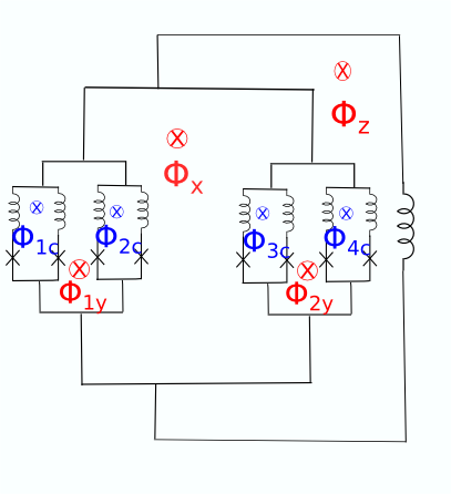
This leads to an effective Hamiltonian of the form
| (11) |
When we substitute in from Eq. 10, this Hamiltonian becomes
| (12) |
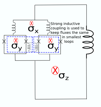
V Conclusions
We have demonstrated an architecture for a universal quantum computer using Heisenberg spin chains and clusters. This architecture has the advantage that it can be implemented adiabatically and therefore has all of the advantages of adiabatic quantum computing. It has already been demonstrated in Chancellor2012 that the single qubit gates and data bus used in this computer can be implemented with high fidelity for reasonable annealing time. We further demonstrate that a controlled NOT gate can be implemented at high fidelity with a reasonably short annealing time and reasonable Hamiltonian parameters.
In addition to suggesting an architecture, we also propose a design to physically realize this architecture. We suggest a method for building superconducting flux qubit systems which model the low energy degrees of freedom of a Heisenberg model. Because the architecture we propose can be implemented adiabatically, only the low energy degrees of freedom need to be reproduced. We choose a superconducting flux qubit implementation because of the experimental success of these systems in performing non-universal adiabatic quantum computing with an Ising spin glass model. Furthermore it has been shown that these Ising spin glass models can be realized accurately enough that the degeneracy of the ground state manifolds is not broken. The universal Heisenberg spin based computer would represent a significant improvement over the current non-universal Ising systems because it would allow these computers to implement important algorithms which the Ising spin glass system has not been able to, such as Shors algorithm for factoring large numbers Johnson2011 ; Harris2010-1 ; Perdomo2008 ; vanderPloeg2006 ; Harris2010-2 .
Acknowledgements.
The authors would like to thank P. Zanardi, I. Marvian, S. Boixo, D. A. Lidar, L. C. Venuti, and S. Takehashi for helpful conversations. Some numerical calculations were performed on the USC high performance computing cluster. This research is partially supported by the ARO MURI grant W911NF-11-1-0268.VI Appendix
VI.1 Review of adiabatic quantum data bus
The adiabatic data bus protocol discussed here is a process in which an even length anti-ferromagnetic Heisenberg spin chain prepared in its ground state is joined adiabatically slowly to a single spin in a state . A spin is also removed from the opposite side of the chain, again adiabatically slowly. The final removed spin will again be in the state . The Hamiltonian for this protocol is
| (13) |
where and are the annealing schedules, functions chosen such that , , , and . This protocol can also be generalized to an XYZ and J1-J2 spin chain (see Chancellor2012 for more details). For simplicity let us consider this protocol with a linear annealing schedule such that
| (14) |
and
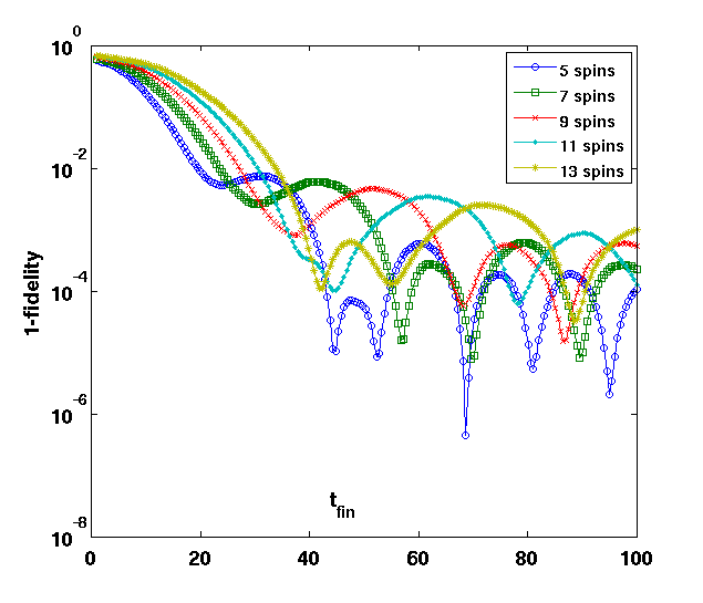
The results of this annealing protocol can be seen in Fig. 7.
VI.2 Calculation of twist for Hadamard gate
Showing how to implement any given single spin gate using this method is straightforward. Take for example the Hadamard gate ,
| (15) |
We now consider the action of on the eigenvectors of the Pauli spin matrices, first for :
Similarly for :
And for :
In this case the phase factor () is irrelevant because of the overall U(1) symmetry.
VI.3 Detailed discussion of simplifying assumptions for superconducting flux qubits
The last term in Eq. 8 is a constant which is not relevant for this discussion. However the other constants in this term are relevant and are defined as follow (Eq. B4b-f in Harris2010-1 )
| (16) |
| (17) |
| (18) |
| (19) |
| (20) |
Here we need the additional definitions:
| (21) |
| (22) |
| (23) |
Let us make the simplifying assumption that all of the critical currents are equal, . In practice there is variability in junction fabrication, but this error can be compensated by building a CCCJJ device (see Fig. 5). This assumption causes the equations to simplify greatly because , which has the consequence that and . We can further assume that in our design that , this additional assumption causes and , which in turn causes . After this simplification we now have
| (24) |
| (25) |
References
- (1) N. Chancellor and S. Haas 2012 New J. Phys. 14 095025 (2012).
- (2) F. Meier, J. Levy, D. Loss, Phys. Rev. B 68, 134417 (2003).
- (3) S. C. Benjamin and S. Bose, Phys. Rev. Lett. 90, 247901 (2003).
- (4) P. Zanardi and M. Rasetti, Phys. Lett. A264 (1999) 94-99
- (5) J. Pachos and P. Zanardi, Int. J. Mod. Phys. B15 (2001) 1257-1286
- (6) G. F. Xu, J. Zhang, D. M. Tong, Erik Sjoqvist, L. C. Kwek, Physical Review Letters 109, 170501 (2012)
- (7) Vahid Azimi Mousolou, Carlo M. Canali, Erik Sjoqvist arXiv:1209.3645 (2012)
- (8) L. Faoro, J. Siewert, and R. Fazio Phys. Rev. Lett. 90, 028301 (2003)
- (9) P. Solinas, P. Zanardi, N. Zanghi, F. Rossi, arXiv:quant-ph 0301090v1 (2003)
- (10) J. M. Renes, A. Miyake, G. K. Brennen, S. D. Bartlett arXiv:1103.5076 (2011)
- (11) D. Bacon, S. T. Flammia, G. M. Crosswhite, arXiv:1207.2769 (2012)
- (12) M. W. Johnson et al. Nature 473, 194-198 (12 May 2011)
- (13) R. Harris et al. Physical Review B 81, 134510 (2010)
- (14) A. Perdomo et al. Physical Review A 78, 012320 (2008)
- (15) S. H. W. van der Ploeg et al. IEEE Trans. App. Supercond. 17, 113 (2006)
- (16) R. Harris et al. Phys. Rev. B 82, 024511 (2010)
- (17) S. Boixo, T. Albash, F. M. Spedalieri, N. Chancellor, D. A. Lidar arXiv:1212.1739 (2012)
- (18) Z. Chen, Z. Zhou, X. Zhou, X. Zhou, and G. Guo, Phys. Rev. A 81, 022303 (2010)
- (19) R. Chitra, S. Pati, H. R. Krishnamurthy, D. Sen, Diptiman, S. Ramasesha Phys. Rev. B 52, 6581 - 6587 (1995)
- (20) L. Banchi, T. J. G. Apollaro, A. Cuccoli, R. Vaia, and P. Verrucchi, Phys. Rev. A 82, 052321 (2010)
- (21) L Banchi, T J G Apollaro, A Cuccoli, R Vaia, and P Verrucchi, New Journal of Physics 13 (2011) 123006
- (22) T. J. G. Apollaro, L. Banchi, A. Cuccoli, R. Vaia, P. Verrucchi, arXiv:1203.5516v1 [quant-ph] 2012
- (23) L. Banchi, A. Bayat, Paola Verrucchi, and Sougato Bose, Phys. Rev. Lett. 106, 140501 (2011)
- (24) Nielsen, Michael A. & Chuang, Isaac L. (2000), Quantum Computation and Quantum Information, Cambridge University Press
- (25) N. Chancellor and S. Haas, Phys. Rev. B 84, 035130 (2011)