Electric sail, photonic sail and deorbiting applications of the freely guided photonic blade
Abstract
We consider a freely guided photonic blade (FGPB) which is a centrifugally stretched sheet of photonic sail membrane that can be tilted by changing the centre of mass or by other means. The FGPB can be installed at the tip of each main tether of an electric solar wind sail (E-sail) so that one can actively manage the tethers to avoid their mutual collisions and to modify the spin rate of the sail if needed. This enables a more scalable and modular E-sail than the baseline approach where auxiliary tethers are used for collision avoidance. For purely photonic sail applications one can remove the tethers and increase the size of the blades to obtain a novel variant of the heliogyro that can have a significantly higher packing density than the traditional heliogyro. For satellite deorbiting in low Earth orbit (LEO) conditions, analogous designs exist where the E-sail effect is replaced by the negative polarity plasma brake effect and the photonic pressure by atmospheric drag. We conclude that the FGPB appears to be an enabling technique for diverse applications. We also outline a way of demonstrating it on ground and in LEO at low cost.
keywords:
electric sail , photonic sail , propellantless propulsion , plasma brake , deorbiting , atmospheric drag deorbitingurl]http://www.electric-sailing.fi
1 Introduction
The spinning electric solar wind sail (E-sail) [1, 2, 3] and the spinning heliogyro photon sail [4, 5] have been proposed for propellantless interplanetary travel. Likewise, various LEO deorbiting devices based on Coulomb drag [8, 9] and atmospheric drag [10, 11] have been proposed for mitigating the space debris problem by deorbiting satellites after their mission is complete and by deorbiting already existing junk objects by attaching braking devices to them.
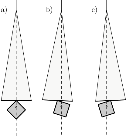
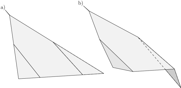
In this paper we consider a freely guided photonic blade (FGPB) which is part of a spinning system so that it is kept stretched by the centrifugal force. In ground-based conditions we can mimic the centrifugal force by gravity (Fig. 1a). If a ballast mass is moved sideways (Fig. 1b,c), a difference between the centre of mass and centre of photon pressure is created and consequently the photon pressure starts to turn the blade about the vertical axis. This gives a simple way to control the blade’s orientation with respect to sunlight and thus to control the direction of the photonic thrust vector.
Throughout the paper we treat the heliogyro photonic blades as rigid objects. Although the blade is in reality free to bend and is not made of rigid material, the rigid body approximation is valid if the shape of the blade does not differ markedly from a planar surface. This is the case if the membrane is lightweight in comparison to the mass of the remote unit which controls it or if the spin of the sail is fast so that the centrifugal force acting on the blade is much larger than the actuated part of the photon pressure force. If the blade is made very long and if it is actuated from either end, it tends to twist in response to actuation instead of tilting uniformly. Problems due to twisting and bending increase in severity if the blade’s aspect angle 111See Nomenclature at end of paper (length versus width) is made larger. In the formulas of this paper the aspect ratio appears as a free parameter. This allows us to e.g. compare the packing efficiency of different sail concepts in a regime where both are configured with the same aspect ratio.
The structure of the paper is as follows. We first treat the traditional photonic heliogyro and its issues, then consider the improved FGPB heliogyro variant and then consider a scalable and modular E-sail by adding tethers to the heliogyro. After that we outline analogous LEO deorbiting applications for both E-sail and heliogyro, discuss briefly FGPB implementation and demonstration options and close the paper with a summary and outlook.
2 Review of traditional heliogyro
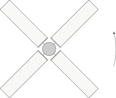
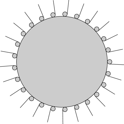
The traditional heliogyro [4, 5] (Fig. 2) is a type of solar photon sail which has several benefits compared to three-axis stabilised square sails. Recently the heliogyro concept has received renewed interest with more detailed dynamical models of blade dynamics [6] and news strategies for managing blade twisting [7]. The heliogyro spacecraft deploys its sheetlike photonic blades from storage reels located on its perimeter. The blade tilting angle (analogous to the angle of attack of helicopter blades) can then be controlled mechanically from the main spacecraft to enable photonic thrust vectoring with or without spinplane turning as well as to have a capability to modify the spin rate [5]. The heliogyro is simple to manufacture and to qualify because the sail membrane is not a large continuous two-dimensional piece but instead consists of rolled sheets similar to those normally used in industry to store and transport thin film materials. Also, because the sail material is nowhere folded and the system uses the centrifugal force for deployment and stretching, the deployment sequence can be demonstrated on ground simply by simulating the centrifugal acceleration by Earth’s gravity field. The Coriolis acceleration of the spinning configuration in space cannot be simulated by gravity on Earth, but it can be made small by selecting a slow speed of deployment.
An issue with the heliogyro is, however, that with the limited physical dimensions usually available for the main spacecraft inside the payload fairing of the launch vehicle, the total area of the photonic sail is limited. Consider the case where the radius of the stowed configuration has some set value and let us compute the maximal sail area as a function of the number of the blades, under the assumption that the maximum aspect ratio of the blade (length versus width) is . To simplify the analysis let us ignore the thickness of the reels. The sail is then spanned by a regular polygon enclosed within a circle with radius . The side length of the polygon is , the blade length by our assumption, and the total area of the blades is given by
| (1) |
Table 1 gives the sail area for various from Eq. (1). Also the area of the largest inscribed disk inside the polygon is given which is representative of the space available for the payload. We see from Table 1 that the optimum choice in terms of sail area is , but is almost as good and it provides a two times larger payload space. We therefore adopt the four blade design (Fig. 2) as representative of the traditional heliogyro in this paper. We emphasise that the four blade optimum applies only to the traditional heliogyro, not the new FGPB heliogyro which is introduced in the next section.
| Sail area | Payload space | |
|---|---|---|
| 2 | ||
| 3 | ||
| 4 | ||
| 5 | ||
| 6 | ||
| 7 | ||
| 8 |
The maximum value of is limited by a risk that the blades might no longer be kept straight by the centrifugal force is they are excessively long. A maximal of 1000 was reported in the early analysis [4] and more recent numerical calculations were in agreement with this [5]. However, a more conservative value of such as might be preferable in first flight models.
If and m so that the spacecraft fits in a medium class launch vehicle, the maximum sail area for is 18000 m2, providing about 140 mN of thrust at 1 au. The membrane mass is then 205 kg if made of similar 7.6 m polyimide film as the IKAROS solar sail [12]. If the total mass of the spacecraft is taken to be e.g. 500 kg, the characteristic acceleration is 0.2 mm/s2 at 1 au.
3 FGPB heliogyro with freely guided blades
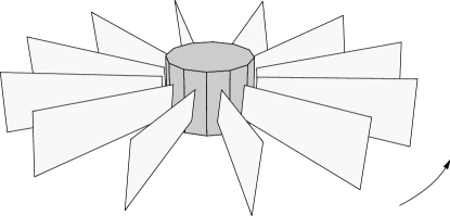

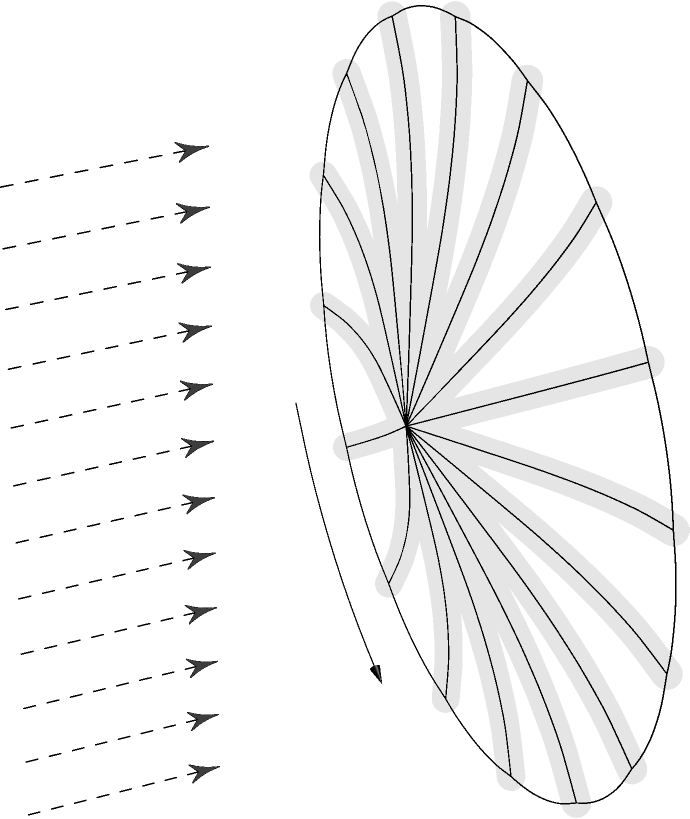
Consider a heliogyro with triangular blades, the tipped ends of the blades being attached to the spacecraft after deployment (Figs. 3-5). The deployment is performed from rolls that are mounted almost vertically on the main spacecraft. In the early phase of the deployment (Fig. 4) the blades remain almost vertical because the centrifugal force prevents them from twisting. At the end of the deployment (Fig. 5) the tipped end of the blade is however free to rotate and the blades align themselves horizontally. This is so because mass elements that are not exactly on the blade’s longitudinal axis are slightly farther away from the spacecraft’s axis of rotation when the blade lies horizontally compared to when it is oriented vertically.
In deployed configuration (Figs. 3 and 5) the attack angle of the blades is controlled continuously by changing the blade’s centre of mass relative to its centre of photon pressure. The actuation can be done by a moving mass at the end of the blade as sketched in Fig. 1; the gravity field shown in Fig. 1 is however now replaced by the centrifugal acceleration which is due to the sail’s spin. Alternatively, one could control the blade’s attack angle by changing its optical properties so that the centre of photon pressure changes. Whereas the blade attack angles are controlled by mechanical twisting actuators from the main spacecraft in the traditional heliogyro (Fig. 2), in the FGPB heliogyro they are controlled by the blade itself. This requires that the blades are autonomous units which are commanded from the main spacecraft, but the benefit is that more sail area can be fitted in a given launcher volume (Fig. 3 and subsection 3.2 below).

As mentioned above, the heliogyro has several theoretical advantages relative to other photon sails concepts such as no need for long rigid booms, no need to fold the sail and the possibility of using roll to roll methods in manufacturing of the sail. On the other hand, a heliogyro platform must always spin which can be an inconvenience for missions requiring accurate pointing or docking.
3.1 Calculation of flattening natural torque
Let us now calculate the torque that tends to make the blade to lie horizontally in the spin plane. Consider a simplified model of the triangular blade in Fig. 6. We assume that the blade (height ) has uniform areal mass density and an additional point mass resides at the middle of the blade’s far end, representing the mass of the remote unit needed to actuate the centre of mass change. We calculate the change in the centrifugal potential energy when the blade is tilted to an angle angle from the spin plane. a nonzero situation is similar to the geometry shown in Fig. 6 except that the blade’s height becomes less and its areal mass density is correspondingly increased:
| (2) |
The centrifugal potential energy of the blade is
| (3) | |||||
For calculating the twisting torque, only terms that depend on are needed. The product is equal to so it does not depend on . Thus, only the last integral term depends on through and we obtain
| (4) | |||||
where in the last step we used and absorbed the offset into the unimportant constant. The torsional torque is
| (5) |
where is the mass of the triangular blade. The angular equation of motion of the blade which describes tilting oscillations is
| (6) |
where is the blade’s moment of inertia about its longitudinal axis. Thus the angular equation of motion becomes
| (7) |
which for small oscillations reduces to . Because this is the equation of a harmonic oscillator at frequency , we conclude that in the limit of small oscillations i.e. linear dynamics, the oscillation angular frequency of small tilting oscillations is the same as the sail’s spin period. A small extra calculation shows that this result is valid also for other than triangular shaped blades.
The centrifugal potential energy of the mass did not enter the calculation because its distance from the spin axis does not depend on . Of course, once the mass is actively moved from the symmetry position as in Fig. 1, the value of affects on how fast the blade’s orientation responds to the actuation.
We must now consider if the natural torque given by Eq. (5) which tends to zero the blade’s tilting angle is typically much smaller than a conveniently achievable actuating torque caused by shifting the centre of mass with respect to the centre of the photon pressure, for values of that one wants to achieve. The worst case (largest natural torque) occurs when the tether length . In this case the centrifugal force acting on the blade is ( is the blade length)
| (8) | |||||
The total centrifugal force is the sum of and a centrifugal force acting on the -mass remote unit, .
The photonic thrust exerted on the triangular blade is given by
| (9) |
where is the solar radiation pressure. We demand that so that blade bending due to radiation pressure is small. We parametrise this by writing where is a large enough number, e.g. . We then compute by which distance the centre of mass has to differ from the centre of radiation pressure of the blade to balance the natural torque (Eq. 5) by an actuated photonic torque which is (as an order of magnitude estimate ignoring some geometrical factors) given by . From the torque balance requirement we solve for . Using Eqs. (5), (8) and we obtain
| (10) | |||||
Inserting reasonable conservative values and one sees that the resulting is nearly three orders of magnitude smaller than the width of the blade . Including the effect of the remote unit would make even smaller because for a given blade tension it would decrease and thus the natural torque . Thus, the actuating photonic torque can easily overcome the natural restoring torque.
3.2 Packing efficiency of FGPB heliogyro
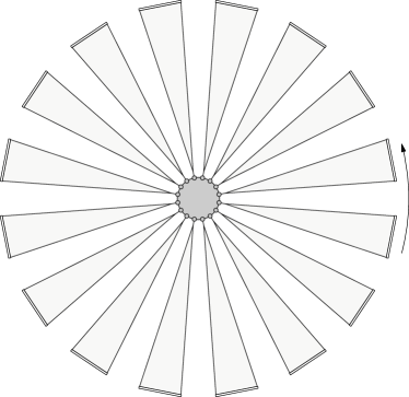
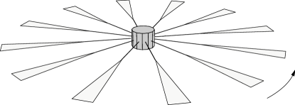
Figure 7 shows a top view of the FGPB heliogyro design in case of a cylindrical main spacecraft. In reality the reels would not be installed exactly vertically, to give the blades a small initial obliqueness so that they would settle in a predictable direction without a need for photonic actuation during deployment.
We shall now estimate how much total sail area can be packed in a cylindrical spacecraft of radius . We assume that the height of the cylinder is , because then all three principal moments of inertia coincide if the mass density of the cylinder is homogeneous. In this way we maximise the height of the cylinder to maximise the blade area while keeping the spin-aligned inertial moment (marginally) larger than the other components to ensure rotational stability in all phases. We also assume that the reels are positioned along the cylinder’s wall by leaving an equal amount of clearance between them than the reel diameter. This is to leave room between the reels where to store the remote units. Then the number of blade reels with radius that fit on the perimeter of the cylinder is (Fig. 7)
| (11) |
If one neglects the inner radius of the reel, the storage volume of a blade reel is which must be equal to the stowed volume of the blade where is the blade’s thickness. From this condition one can solve the reel radius to obtain
| (12) |
The total area of the blades is
| (13) |
Equation (13) can be compared with the corresponding law of the traditional heliogyro for which (Table 1). Their ratio is
| (14) |
The factor is large whereas is at most 1000. If m, m and , the area ratio is . Thus the FGPB heliogyro concept allows one to pack more sail area in a spacecraft of a given cylindrical volume. If one uses a more conservative blade aspect ratio such as , the relative benefit of the FGPB design becomes larger. Also, if one introduces a thinner sail material (smaller ), the FGPB design can host a larger sail without increasing , whereas for the traditional heliogyro the maximum area of the sail is essentially independent of the membrane thickness.
4 E-sail with FGPB spin management
The traditional E-sail (Fig. 8) uses auxiliary tethers to ensure that the main tether do not collide in the varying solar wind [3]. The remote units at the tips of the main tethers need some spinup thruster and the same thruster can also be used to modify the spin rate during E-sail flight. The thruster can be a cold gas thruster, a FEEP thruster [13], a photonic blade thruster [14] or some other thruster. The photonic blade thruster as is the subject of this paper has the benefit of having infinite specific impulse so that there the capability to modify the spin rate during the mission is large. Modification of the spin rate may be needed to overcome a secular change of the spin rate due to the heliocentric orbital Coriolis force [15, 14]. In specific missions one might also want to modify the spin rate for some other reason.
We also introduced the idea [14] that by making the photonic blades larger one could get rid of the auxiliary tethers which would simplify the E-sail design and make it more scalable and modular (Fig. 9). In this case the photonic thrust must be large enough to overcome the tendency of the tethers to come together by random changes of the solar wind. This variant of the E-sail is scalable and modular because the number and length of the main tethers are no longer tied together by a necessity to connect their tips by auxiliary tethers. This configuration is entirely similar to the FGPB heliogyro considered in section 3. The only difference is the existence of a long E-sail tether between the main spacecraft and the photonic blade, and the fact that the photonic blade is smaller because it is only used as an auxiliary propulsion device for the E-sail control purpose.
In the traditional E-sail which uses auxiliary tethers, if the tether length is 20 km, the E-sail force per length 500 nN/m their and the tether tension 5 cN, we found earlier [14] that 2.7 m2 blade area per tether is sufficient and that the blade area requirement is independent of the heliocentric distance. For the new design which does not have auxiliary tethers, we made some numerical experiments where the E-sail is flown in real solar wind that for the nominal 20 km E-sail tether length, the required blade area per tether is 16-20 m2.
In the FGPB design one could have, for example, a low-end E-sail with four tethers, each 20 km long, and 40 mN total nominal E-sail thrust at 1 au. The total mass of the blade membranes would be 1.5 kg, if each is 20 m2 large and made of 12.6 m ITAR-free thin metallised kapton while the E-sail tethers would weigh 0.9 kg if made using our standard 4-fold Heytether construction with 25 m loop and 50 m base aluminium wire [16]. Allowing for 0.3 kg for each main tether reel, 0.3 kg for each remote unit which controls the blade’s orientation by shifting the centre of mass or other method [14], and 1.2 kg for the 40 W/20 kV electron gun and its high voltage source, the total mass of the E-sail hardware would be only 6 kg in this case, yielding a specific acceleration at 1 au of 6.7 mm/s2. By specific acceleration we mean the thrust divided by the propulsion system’s (initial) mass. For example, this 6 kg E-sail device could carry a spacecraft whose total mass is 80 kg at 0.5 mm/s2 characteristic 1 au acceleration which is equivalent to 15 km/s/year delta-v capability. Furthermore the E-sail acceleration decays as with solar distance which is slower than the effective thrust decay of photonic sail and solar electric propulsion.
We also want to point out that there is a natural continuum of hybrid E-sail/photonic sail engineering possibilities between the purely photonic heliogyro and the photonically guided E-sail. These hybrid designs would use the E-sail effect in interplanetary space and revert to photonic propulsion inside the magnetosphere where the solar wind does not exist. In hybrid design the photonic blades would typically be much larger in area than what is needed for the E-sail control alone.
5 Deorbiting applications of FGPBs
In low Earth orbit (LEO), force due to the atmospheric molecular flow overcomes the solar photonic force typically below 800 km altitude. Also in LEO, charged tethers can be used for generating a Coulomb drag plasma brake effect [8, 9]. The plasma brake is similar to the E-sail except that it uses a negatively biased tether to keep the gathered current and power consumption small. It seems that a negative tether is more beneficial in the ionosphere while a positive tether is better in the solar wind [8, 3]. Both positive and negative polarity tethers generate a Coulomb drag effect where force is exerted on the tether which is aligned with the tether-perpendicular component of the plasma flow in the tether’s frame of reference.
One could use the FGPB heliogyro device of section 3 (Fig. 5) in LEO directly as a neutral drag deorbiting device. The photonic pressure would simply be replaced by or augmented by the pressure due to the molecular ram flow of the upper atmosphere. Manoeuvring remains at least qualitatively similar because molecular flow behaves much in a same (although not completely similar) way as the radiation pressure.
Analogously, a device similar to the FGPB E-sail described in section 4 (Fig. 9) could be tuned for LEO deorbiting. The tether lengths and thickness might have to be changed to accommodate a possibly larger Coulomb drag (depending on the plasma density and thus altitude) and to resist the tendency of Earth’s gravity gradient to disturb a spinning tether rig. Above km the blades would use solar photonic pressure for tether dynamical control (similar to the E-sail), below this altitude they would primarily use the atmospheric drag for the same purpose. If wanted for some mission specific reasons, the traditional electrodynamic tether Lorentz force could also be available from the same tethers by charging them positively and thereby letting them collect a larger current. The active electrodynamic tether mode would allow also orbit inclination change and orbit raising manoeuvres in addition to only braking. The original single-tether gravity stabilised plasma brake device [9] can deorbit up to kg debris payloads (an exact mass limit cannot be given since it depends on the time available for the deorbiting task). With a spinning tether rig, the device could be scaled up by the number of tethers, thus making it potentially feasible to apply the efficient plasma brake effect to multi-tonne debris object orbit lowering tasks. Of course, for large debris objects which do not burn completely in the atmosphere, one would still have to use a chemical kick in the final phase so that the object reenters over an uninhabited ocean area.
6 Implementation and demonstration of FGPB
Implementing the freely guided photonic blade calls for a controllable way of creating a difference between the centre of mass and centre of photonic pressure of the blade. One way to do it is to have a moving mass as shown in Fig.1. In our earlier paper we similarly considered a bar-shaped remote unit inside which there is a sliding mass [14].
If flat bending devices are available, the FGPB might also be actuated by flaps as shown in Fig. 10. In this case, even the control electronics might be printed on the blade so that no physical “remote unit” would be needed since the blade itself would contain the flap actuated mechanism. Alternatively, if one wants to avoid bending parts, actuation could be accomplished by modifying the optical properties of the blade. The Japanese IKAROS mission uses technology borrowed from liquid crystal displays (LCDs) for this purpose [12]. One might also cover a significant fraction of the blade by thin film solar panels and modify their optical properties by short-circuiting them. The power gathered by the non short circuited areas could be used for resistive heating of a suitable near edge area of the blade to enhance the photonic torque available from such actuation.
To increase the technical readiness level (TRL) of the FGPB to 4-5, the controllability of the FGPB should be demonstrated on ground in a vacuum chamber equipped with a solar simulator or other artificial photon source, by using Earth’s gravity field to simulate the centrifugal force (Fig. 1). One would demonstrate a capability to turn the hanging photonic blade to an angle given by remote command by a controlled change of its centre of mass or optical properties.
To increase the TRL of FGPB to 7, the system could be taken to a CubeSat for orbital demonstration. One would set the CubeSat to spin e.g. by magnetorquers and then deploy the blade from a roll followed by a tether, similar to the ESTCube-1 CubeSat which is launched in March 2013 to measure the E-sail effect in orbit [3, 17]. One would then demonstrate that one can tilt the blade controllably by photonic thrust and thereby modify the spin state of the tether plus blade system according to commanding. One could use 1-4 FGPB tethers depending on how much space there is available on the particular CubeSat. One tether is enough to demonstrate the necessary controllability and manoeuvres, however, because multiple tethers are dynamically only weakly dependent on each other through the central spacecraft. After reaching TRL 7 with one tether, one could probably build multi-tether FGPB E-sails and heliogyros for interplanetary travel and deorbiting without additional system-level space demonstrations.
7 Summary and outlook
| Concept | Characteristics |
|---|---|
| Square sail | +High TRL 7 in small scale |
| -Scaling is nontrivial problem | |
| Traditional heliogyro | -Scalability limited by launcher diameter |
| FGPB heliogyro | +Scalable |
| -Needs continuous active control |
| Concept | Characteristics |
|---|---|
| E-sail with aux. tethers | +Reasonably high TRL 4-5 |
| -Auxiliary tether ring is single point failure | |
| FGPB E-sail | +Very good scalability and modularity |
| +No single point failures | |
| -Needs continuous active control |
We surveyed propellantless propulsion applications of freely guided photonic blades (FGPBs) in the context of photonic sails (Table 2) and electric sails (Table 3). The FGPBs can be used as scalable photonic sails directly or as control propulsion for E-sails. Hybrid photonic-E-sails are also conceivable. Outside of Earth’s magnetosphere where the solar wind is available as a thrust source, E-sails can provide potentially much higher performance than photonic sails [3].
We also showed that the blades have a natural dynamical tendency to settle in the spin plane which is actually helpful in deployment phase, and that the tendency can be easily overcome by actuated photonic thrust during flight. We identified and considered the following specific FGPB application domains:
-
1.
FGPB photonic heliogyro sail concept whose packing density is higher than that of a traditional heliogyro.
-
2.
Control propulsion for a scalable and modular variant of the E-sail which does not need auxiliary tethers for dynamical stability.
-
3.
Hybrid photonic-E-sail devices.
-
4.
Various deorbiting devices based on plasma brake and neutral drag effects. These devices are analogous to FGPB E-sails and heliogyros.
We also briefly discussed engineering alternatives for FGPB implementation (based on changing the centre of mass or changing the blade’s optical properties) and outlined a path how the FGPB’s TRL could be raised to 4-5 with simple ground-based demonstration and to 7 by a CubeSat demonstration.
We conclude that FGPB seems to be a technical concept that would enable a potentially large class of very significant applications in propellantless interplanetary propulsion and deorbiting. FGPBs need continuous active control, but this drawback is probably not severe in comparison to the benefits. We consider that raising its TRL as well as looking in more details into its application would therefore be highly motivated.
8 Acknowledgement
The research leading to these results has received funding from the European Community’s Seventh Framework Programme ([FP7/2007-2013]) under grant agreement number 262749. We also acknowledge the Academy of Finland and the Magnus Ehrnrooth Foundation for financial support.
Appendix A Nomenclature
| Heliogyro total blade area | |
| Area of largest inscribed disk inside polygon | |
| Blade thickness | |
| Photonic thrust force (acting on single blade) | |
| Centrifugal force (acting on single blade) | |
| Blade width (also called height), plain and projected | |
| Inertial moment (about long axis) of blade | |
| Heliogyro blade aspect ratio (length per width) | |
| , centrifugal force per photonic force | |
| Blade length | |
| Tether length | |
| Remote unit mass of novel type heliogyro blade | |
| Mass of single novel type heliogyro blade | |
| Number of blades or tether-blade systems | |
| Radiation pressure | |
| Radius of stowed configuration or spacecraft | |
| Radial distance (from spacecraft or from sun) | |
| Blade storage reel outer radius | |
| Centrifugal potential energy of blade | |
| Horizontal coordinate | |
| Vertical coordinate, actuated shifting of centre of mass of blade | |
| Tilting angle of novel type heliogyro blade | |
| Angular rotation rate of novel type heliogyro | |
| Mass per area of blade, plain and projected | |
| Torsional torque, plain and actuated |
| E-sail | Electric solar wind sail, electric sail |
| FEEP | Field effect (or field emission) electric propulsion |
| FGPB | Freely guided photonic blade |
| ITAR | International traffic in arms regulations, set of U.S. regulations |
| LCD | Liquid crystal display |
| LEO | Low Earth orbit |
| RU | Remote unit, autonomous device at tip of each E-sail tether |
| TRL | Technical readiness level |
References
- Janhunen [2004] P. Janhunen, Electric sail for spacecraft propulsion, Journal of Propulsion and Power 20 (4) (2004) 763–764.
- [2] P. Janhunen, A. Sandroos, Simulation study of solar wind push on a charged wire: basis of solar wind electric sail propulsion, Ann. Geophys., 25 (2007) 755–767.
- Janhunen et al. [2010] P. Janhunen, et al., Electric solar wind sail: towards test missions, Review of Scientific Instruments 81 (2010) 111301.
- [4] R.H. MacNeal, The heliogyro, an interplanetary flying machine, NASA Contractor’s Report CR 84460 (1967).
- [5] R.S. Blomqvist, Heliogyro control, Ph.D. thesis, Carnegie Mellon University, Pittsburg, Pennsylvania (2009).
- [6] Guerrant, D.V., D.A. Lawrence and W. Keats Wilkie, Heliogyro solar sail blade twist control, Paper AAS 12-003 in 35th Annual AAS Guidance and Control Conference, Colorado, Advances in the Astronautical Sciences 144: Guidance and control 2012, M.L. Osborne (ed.), (2012).
- [7] Guerrant, D.V., W. Keats Wilkie and D.A. Lawrence, Heliogyro blade twist control via reflectivity modulation, Paper AIAA 2012-1746 in 53rd AIAA Structures, Structural Dynamics and Materials Conference, 23-26 April, Honolulu, Hawaii (2012).
- [8] P. Janhunen, On the feasibility of a negative polarity electric sail, Ann. Geophys., 27 (2009) 1439–1447.
- [9] P. Janhunen, Electrostatic plasma brake for deorbiting a satellite, J. Propulsion Power, 26 (2010) 370–372.
- [10] V. Lappas, N. Adeli, L. Visagie, J. Fernandez, T. Theodorou, W. Steyn, M. Perren, CubeSail: a low cost CubeSat based solar sail demonstration mission, Adv. Space Res., 48 (2011) 1890–1901.
- [11] V. Lappas, S. Pellegrino, H. Guenat, M. Straubel, H. Steyn, V. Kostopoulos, E. Sarris, O. Takinalp, S. Wokes, A. Bonnema, DEORBITSAIL: de-orbiting of satellites using solar sails, Int. Conf. Space Tech., 15-17 Sept. (2011).
- [12] Y. Tsuda, O. Mori, R. Funase, H. Sawada, T. Yamamoto, T. Saiki, T. Endo, J. Kawaguchi, Flight status of IKAROS deep space solar sail demonstrator, Acta Astronaut., 69 (2011) 833-340.
- [13] S. Marcuccio, N. Giusti, A. Tolstoguzov, Characterization of linear slit FEEP using an ionic liquid propellant, IEPC-09-180, Proc. 31th International Electric Propulsion Conference, Ann Arbor, MI (2009).
- [14] P. Janhunen, Photonic spin plane control for solar wind electric sail, Acta Astronaut., 83 (2013) 85–90.
- [15] P.K. Toivanen, P. Janhunen, Spin plane control and thrust vectoring of electric solar wind sail by tether potential modulation, J. Prop. Power, in press (2013).
- [16] H. Seppänen, S. Kiprich, R. Kurppa, P. Janhunen, E. Haeggström, Wire-to-wire bonding of um-diameter aluminum wires for the Electric Solar Wind Sail, Microelectronic Engineering 88 (2011) 3267–3269.
- [17] M. Pajusalu, R. Rantsus, M. Pelakauskas, A. Leitu, E. Ilbis, J. Kalde, H. Lillmaa, R. Reinumägi, K. Voormansik, K. Zālīte, V. Allik, M. Noorma and S. Lätt, Design of the electric power system for the ESTCube-1 satellite, Latv. J. Phys. Tech. Sci., 3 (2012) 16–24, doi: 10.2478/v10047-012-0014-4.