Electronic States of Single-Component Molecular Conductors [(tmdt)2]
Abstract
The electronic states of isostructural single-component molecular conductors [(tmdt)2] ( = Ni, Au, and Cu) are theoretically studied. By considering fragments of molecular orbitals as basis functions, we construct a multiorbital model common for the three materials. The tight-binding parameters are estimated from results of first-principles band calculations, leading to a systematic view of their electronic structures. We find that the interplay between a -type orbital (L) on each of the two ligands and a -type orbital (M) centered on the metal site plays a crucial role: their energy difference controls the electronic states near the Fermi energy. For the magnetic materials ( = Au and Cu), we take into account Coulomb interactions on different orbitals, i.e., we consider the multiorbital Hubbard model. Its ground-state properties are calculated within mean-field approximation where various types of magnetic structures with different orbital natures are found. An explanation for the experimental results in [Cu(tmdt)2] is provided: The quasi-degeneracy of the two types of orbitals leads to a dual state where localized M spins appear, and L sites show a nonmagnetic state owing to dimerization. On the other hand, [Au(tmdt)2] locates in the subtle region in terms of the degree of orbital mixing. We propose possible scenarios for its puzzling antiferromagnetic phase transition, involving the M orbital in contrast to previous discussions mostly concentrating on the L sector.
1 Introduction
Molecular crystals composed of one molecular species showing electrical conduction, i.e., single-component molecular conductors (SCMC) [1, 2], have been revealed to bear novel electronic states. In particular, their multiorbital nature has been recognized, which is different from the situation in conventional charge transfer salts (CTS), where, in most cases, only one molecular orbital (MO) contributes to their electronic properties [3, 4]. In fact, the involvement of different MO is a consequence of the molecular design [5] for realizing SCMC: to make the energy difference between the frontier MO small enough, so that their energy bands can overlap when inter-molecular transfer integrals become sufficiently large. Metal complex molecules of the form ()2 ( = metal, = ligand) are suitable for this purpose. Their frontier MO are approximately bonding and antibonding combinations of the wave functions from the two ligands. Large ligands lead to an effectively small transfer integral between them and result in a small energy difference. Such a situation indicates a two-MO system, which is also realized in some CTS as notably discussed in (dmit)2-based compounds. [6, 7]
The first SCMC in which metallic conductivity was reported [1] is [Ni(tmdt)2] (tmdt = trimethylene-tetrathiafulvalene-dithiolate), [8] whose resistivity decreases by cooling down to lowest temperatures (). Direct evidence of its metallic feature was given by the observation of three-dimensional Fermi surfaces by de Haas-van Alphen oscillations [9], whose results are consistent with first-principles band calculations [9, 10]. Near the Fermi energy , there exist two overlapping bands from different -type MO and crosses the overlapping area. Electron and hole pockets appear, owing to the existence of an even number of electrons in the unit cell consisting of one Ni(tmdt)2 molecule. This is the success of the molecular design mentioned above. It shows Pauli paramagnetic susceptibility, [1] while isotropic magnetoresistance suggesting the spin effect is observed [11] whose origin remains unclear.
Since the discovery of [Ni(tmdt)2], many related compounds have been synthesized. Among them, an isostructural analog but with an odd number of electrons per unit cell, [Au(tmdt)2] [12], has been attracting interest. It shows an antiferromagnetic (AF) phase transition with a transition temperature K [13, 14], which is exceptionally high among molecular conductors. An intriguing point is that in the resistivity, showing a metallic -dependence down to low as well, no anomaly at around is found [15]. Furthermore, the analysis of an NMR measurement [14] suggests the magnetic moment in this AF state to be rather large, i.e., on the order of 1 . These features are distinct from the formation of a spin-density-wave state due to the nesting of Fermi surface, as frequently observed in CTS, where anomalies in transport properties appear and typical values of the magnetic moment are one order of magnitude smaller, or even less [4]. Such a magnetic solution attributed to the bands is actually stabilized in first-principles calculations [16, 17] as well as in a mean-field (MF) study of an effective Hubbard model [18], which faces difficulties in explaining these experimental facts.
Recently, another isostructural member [Cu(tmdt)2], having an odd number of electrons per unit cell, has been successfully synthesized [19]. It shows a semiconductive behavior in contrast to the two compounds above, and exhibits an AF phase transition at K, much lower than in [Au(tmdt)2] [19, 20]. The dependence of magnetic susceptibility above is ascribed to the behavior of the one-dimensional (1D) spin- Heisenberg model with AF exchange coupling of about 150 meV [19], which is consistent with the 1H-NMR nuclear spin-lattice relaxation rate () indicating 1D spin dynamics [20]. In this compound, in contrast with the discussions above, a -type MO centered at the metal site is suggested to lie close to the two ligands orbitals, and mix substantially. The charge transfer from the -MO results in a nearly half-filled -band [21]. Then, the magnetic properties of [Cu(tmdt)2] are attributed to localized spins appearing on the -MO [19, 20].
In fact, the possibility that more than the two -MO are involved in the electronic states of SCMC was first proposed for [Au(tmdt)2] on the basis of first-principles band calculations [16, 17]: The - and -MO mix slightly when forming the electronic band structure, whereas the latter plays the major role near . However, more recently, it has been inferred from experiments that the orbital energy difference between these MO is modified upon cooling by an unusual structural variation, enhancing the mixing [22].
Such multi-MO characters in SCMC can be captured by the effective model approach based on tight-binding approximation, which has been successful in describing the electronic properties of CTS and is now widely used [3, 4, 23]. The observed de Haas-van Alphen oscillations in [Ni(tmdt)2] are consistent with the tight-binding picture [9]. In ref. \citenSeo_2008JPSJ, we proposed that the basis sets for the effective models of [Ni(tmdt)2] and [Au(tmdt)2] can be taken as virtual orbitals whose wave functions are parts of the relevant MO near , rather than the MO themselves. In this paper, we extend our theoretical approach to the newly synthesized [Cu(tmdt)2] and seek for a systematic view of the electronic states among the isostructural family of [(tmdt)2] ( = Ni, Au, and Cu).
In § 2, we set up our effective multiorbital Hubbard model and derive tight-binding parameters by fitting the results of first-principles band calculations. By considering a common set of basis functions for the three materials, a systematic view of the electronic states is achieved. Essentially, the transfer integrals providing the structures of each band are similar among the members, and orbital mixing is mostly governed by the energy difference between the - and -type orbitals.
Then, in § 3, by treating the on-site Coulomb interactions within MF approximation, we investigate the ground-state properties of models for [Au(tmdt)2] and [Cu(tmdt)2]. We will see that orbital mixing brings about phase diagrams showing different magnetic states when Coulomb interactions on the two types of orbitals are independently varied. In particular, a slight enhancement of mixing in [Au(tmdt)2] suggested by experiments [22] results in marked changes from our previous results [18]: The involvement of the orbital is suggested.
Section 4 is devoted to discussions, especially on the magnetic transitions observed in the two compounds. Our results are consistent with the picture that, in [Cu(tmdt)2], the -MO carries 1D = 1/2 localized spins, interpreted as a multiband Mott insulator. We discuss possible situations realized in [Au(tmdt)2], from the viewpoint of doped Mott insulating systems due to orbital mixing. A summary is given in § 5.
2 Effective Model
The wave functions that we chose as basis sets for the effective model of SCMC in our previous work [18] are localized on some portions of the molecules. They can be considered as fragments of the MO, and then called the fragment MO (fMO) in refs. \citenBonnet_2010JCP,Tsuchiizu_2011JPSJ,Tsuchiizu_2012JCP, which we follow in this paper as well.
The original motivation to consider such decomposition of MO was the results of first-principles calculations [16, 17]. The spin-dependent calculation for [Au(tmdt)2] indicates a stable AF pattern where spins align oppositely within each molecule. To understand this unusual situation, it was speculated that a ligand - transfer integral is larger between adjacent molecules than that within a molecule, which is supported by the results of an analysis based on the fMO approach [18]. These features are consistent with the molecular design [5] mentioned in § 1 and imply that the fMO approach gives an insightful picture of the electronic states of SCMC. Such discussions have recently been elaborated within quantum chemistry calculations [24, 25, 26], for (TTM-TTP)I3 and [Au(tmdt)2]. It is shown that the two approaches, the use of the MO and fMO pictures, can be transformed from one to the other. We note that the fMO approach here and the so-called fragment molecular orbital method applied to huge molecules [27, 28] share common concepts.
In the following, all first-principles calculations, including those for MO of isolated molecules, are performed using the computational code QMAS (Quantum MAterials Simulator) [29] based on the projector augmented-wave method [30] with the generalized gradient approximation [31]. See refs. \citenIshibashi_2008JPSJ and \citenIshibashi_2012Crystals for details.
2.1 Molecular orbitals and fragment model
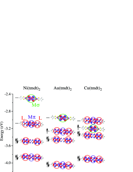
The band structures of isostructural SCMC near are composed of several MO with similar characters upon chemical modifications [2, 16, 17]; this applies to the family of [(tmdt)2] including the new member = Cu [19, 21]. Four MO which mostly contribute to the electronic bands near are shown in Fig. 1.
They can be approximately reconstructed using three kinds of fMO, which we call here M, L, and M. The M and M orbitals are the - mixed wave functions, roughly being an anti-bonding combination of the metal site and orbitals, and the surrounding S orbitals, respectively [32]. The relevant atomic orbitals are 3 for = Ni and Cu, and 5 for = Au. The L orbital is the orbital which is similar to the HOMO of the TTF molecule embedded in the ligands (see ref. \citenKobayashi_2004CR). There are two of them in one molecule, i.e., L1 and L2, one for each ligand; they are equivalent due to the inversion center at the metal site.
In isolated molecules, the M orbital does not mix with other orbitals from their symmetry; thus, it is a MO itself, i.e., the -MO mentioned in § 1. As can be seen in Fig. 1, the other three MO can roughly be described as linear combinations of L and M orbitals [18] as , , and , where and are some coefficients [24] (we omit renormalization factors).
In the fMO scheme, we consider these three kinds of orbitals as a basis set composing the band structures, and then for the low-energy effective model. The two-MO case mentioned in § 1 corresponds to the situation where only the L orbitals are considered. In ref. \citenSeo_2008JPSJ, we chose {L, M} for [Ni(tmdt)2] and {M, L} for [Au(tmdt)2] to reproduce the first-principles band structures near . Here, all {M, L, M} are taken into account as a common set, in order to provide a systematic view of the compounds.
Our model Hamiltonian including local Coulomb interactions reads:
| (1) | |||
| (2) | |||
| (3) |
where and represent the one-particle part, determining the band structure, and the on-site interaction, respectively. In the first term of eq. (2), denotes the transfer integrals between fMO, where the sum is taken for inter-fMO pairs including intra- and inter-molecular ones, and () denotes the annihilation (creation) operator for all kinds of orbitals with fMO site index and spin or . In the second term of eq. (2), and are the orbital energies of the M and M orbitals, with respect to the L level. The sum here, as well as in eq. (3), is taken for the molecule index , where the number operators are and with an orbital index M, L1, L2, or M. The intraorbital on-site Coulomb interactions for the three kinds of fMO are denoted as , , and . As for the interorbital on-site interaction, we only include between M and M for simplicity, considering that these two orbitals share the spatial extent while they are separated from the L orbitals [33].
| bond | site pair | [Ni(tmdt)2] | [Au(tmdt)2] | [Au(tmdt)2] (9 K) | [Cu(tmdt)2] |
| intra-mol. | L1-L2 | -61 meV | -24 meV | -27 meV | -35 meV |
| A | L1-L1, L2-L2 | -86 | -99 | -98 | -90 |
| B | L1-L2 | 221 | 207 | 222 | 250 |
| Q | L1-L2 | 131 | 109 | 129 | 134 |
| P | L1-L2 | 33 | 41 | 46 | 37 |
| A | L1-M, M-L2 | 37 | 33 | 41 | 14 |
| B | L1-M, M-L2 | 27 | 27 | 33 | 29 |
| C | L1-M, M-L2 | -50 | -25 | -29 | -24 |
| R | L1-M, M-L2 | 21 | 22 | 27 | 14 |
| intra-mol. | L1-M, M-L2 | -200 | -138 | -127 | -188 |
| B | L1-M, M-L2 | 0 | 30 | 35 | 20 |
| C | L1-M, M-L2 | -22 | -5 | -22 | -7 |
| Q | L1-M, M-L2 | 5 | 15 | 14 | 11 |
| A | M-M | 82 | 95 | 98 | 96 |
| A | M-M | -13 | -23 | -30 | -19 |
| B | M-M | 24 | 37 | 44 | 50 |
| A | M-M | 53 | -34 | -14 | -1 |
| orbital energies | |||||
| 879 meV | 522 meV | 476 meV | 181 meV | ||
| -193 | -612 | -636 | -377 | ||
| orbital occupancies | |||||
| 0.02 | 0.03 | 0.09 | 0.86 | ||
| 1.16 | 1.50 | 1.47 | 1.15 | ||
| 1.66 | 1.97 | 1.97 | 1.85 |
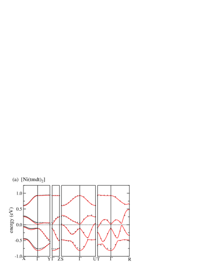
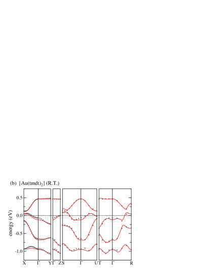
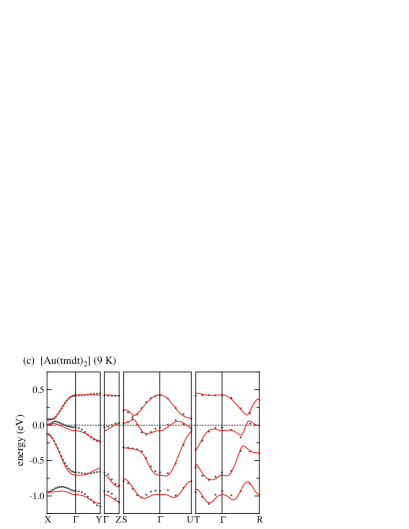
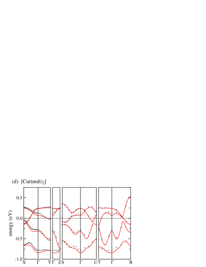
2.2 Fitting to first-principles band calculations
The tight-binding parameters are obtained by a numerical fitting to first-principles band structures for the nonmagnetic state. In Fig. 2, we show the bands near , together with the fitted tight-binding dispersions. The four bands originate from the four MO, or equivalently, the four fMO; The unit cell consists of one molecule. As for [Au(tmdt)2], calculations were performed for both room- and low- (9 K) structures determined experimentally, due to the indication of a structural variation upon cooling [22], as noted above. In the calculations for [Ni(tmdt)2] and [Cu(tmdt)2], the room- structure parameters are used.
One can see that the top band in [Ni(tmdt)2] and the bottom band in [Au(tmdt)2] are separated from the others. This is the reason we previously used three-band fits (two kinds of fMO) [18]. On the other hand, in [Cu(tmdt)2], all four bands are overlapping, requiring a four-band fit for a reasonable agreement with the first-principles band structure. Note that the total band widths of the four bands are about 1.7 eV ( Ni) 1.6 eV (Au) 1.3 eV (Cu).
The fitted tight-binding parameters together with the orbital occupancies per site calculated from , i.e., ( M, L, M), are listed in Table 1. The listed orbital energies, , and , are obtained by fitting the energy dispersions of . By noting that the first-principles band structures are obtained self-consistently including the Hartree contributions within the interactions, we can make a correspondence between the fitted values and the orbital energies in eq. (1) as [18, 26, 34]
| (4) | ||||
| (5) |
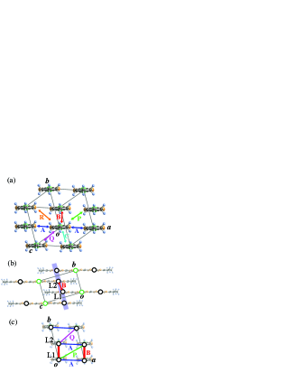
The transfer integrals show more or less similar values for all three members [35], which is due to the fact that they are isostructural, as noted in our previous work [18]. The M orbitals have a large only for the A bonds along the [100] direction: they show a 1D structure. The L orbitals, on the other hand, possess a two-dimensional network, where the inter-molecular dimers are formed by B bonds. Their network is schematically shown in Figs. 3(b) and (c); in the unit cell, the two L sites from different molecules form L1-L2 dimers. The degree of dimerization, represented by the intradimer transfer integral, namely, that along the L1-L2 B bond, is largest in [Cu(tmdt)2]. This dimerized structure resembles the situation commonly seen in typical CTS, e.g., in TM and polytypes of ET such as the and -types [4, 3]. M orbitals, in contrast, do not have large between them, but bridge L layers mainly along the intramolecular bonds. They are appreciable (0.1 - 0.2 eV) and then these two orbitals mix with each other. The main differences between the three compounds are in orbital energy, which we will discuss in the next subsection.
2.3 Systematic view of electronic structures
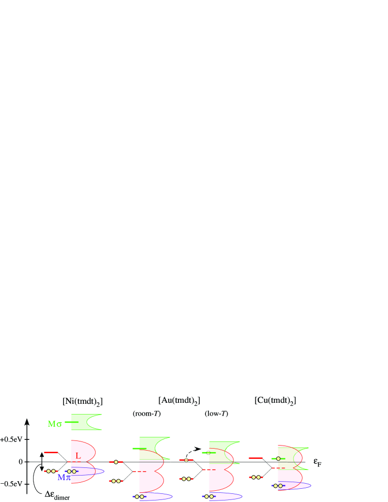
The orbital energies and together with the transfer integrals determining the band structures, and the electron numbers, 4 ( = Ni) or 5 ( = Au, Cu) in the four orbitals, lead us to a systematic view of this family, as shown in Fig. 4.
The M level is low in energy but mixes with the L bands particularly in [Ni(tmdt)2] and [Cu(tmdt)2]; deviates from 2, as seen in Table 1. However, as far as the main characteristics of the electronic states near are concerned, the M orbital does not play an important role. Then, is the essential difference among the three members, controlling the orbital mixing between the M and L orbitals. It becomes monotonically small as = Ni Au (room-) Au (low-) Cu. This gives rise to a crucial difference in the magnetic states of the Au and Cu systems, as will be shown in § 3.
The M level in [Ni(tmdt)2] is high, and approximately 2 electrons enters the L level. The existence of two L sites in the unit cell, which show dimerization as discussed in the previous subsection, results in band splitting, but not large enough to generate a direct band gap. Then electron and hole pockets appear and compose the Fermi surface. This is how the first SCMC with a metallic character was realized.
Comparing the room- and low- structure parameters for [Au(tmdt)2], the low- data show slightly larger transfer integrals than the room- data especially in L-L pairs; this is naturally expected from the thermal contraction. is reduced by lowering by about 0.05 eV, which is consistent with the previous MO calculation [22]. As a result, a fraction of electrons in the L sites, nearly 3/4-filled in the room- parameters, are transfered to the M orbital in the low- parameters: {, } = {0.03, 1.5} (room-) {0.09, 1.47} (low-).
As for [Cu(tmdt)2], M mixes more with L due to the further reduction in , by about 0.30 eV smaller than the low- parameter for [Au(tmdt)2]. In particular, near , the contribution of M is appreciable [21], even though the orbital level scheme shows a positive . This is because L orbitals have larger with a two-dimensional character, while the M band is 1D; therefore, the former show wider bands. The orbital occupancies are {, } = {0.86, 1.15}, which are substantially varied from the cases above. These features are close to the situation in the MO scheme in Fig. 1: In Cu(tmdt)2, the M () orbital is occupied with nearly one electron.
Let us comment on the relation between our level scheme and the nominal charges given as Ni2+[(tmdt)-]2, Au3+[(tmdt)1.5-]2, and Cu2+[(tmdt)-]2. Their corresponding occupations of metal levels are Ni:(3)8, Au:(5)8, and Cu:(3)9, respectively. When one hypothesizes that the M and M levels are ‘’ levels of the metal atoms and the L orbitals for the full charge of the ligands (namely, omit - mixing, which is actually large), these nominal charges correspond to, (M)2[(L)1]2, (M)2[(L)1.5]2, and (M)2(M)1[(L)1]2, respectively, namely, a full-filled M in all compounds, and, (i) in = Ni, a 1/2-filled L band, (ii) in = Au, a 3/4-filled L band, and (iii) in = Cu, a 1/2-filled M band and a 1/2-filled L band. These are close to the situations in Fig. 4.
3 Mean-Field Calculation
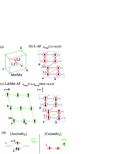
As mentioned in § 1, [Au(tmdt)2] and [Cu(tmdt)2] show phase transitions to magnetically ordered states. Here, we study their ground-state ( = 0) magnetic states where the interaction terms in [eq. (3)] are treated by MF approximation as . Such a MF treatment is suitable in seeking for possible different states, as in our model here with multiple degrees of freedom. In the calculations, we consider a supercell of , which includes {M, L (L1 and L2), M} 8 orbitals [see Fig. 5(a)].
We set the values of to the fitted results in Table 1, while and are adjusted by the conditions in eqs. (4) and (5) when the interaction parameters are varied. Then the band dispersions are unchanged within the paramagnetic metallic (PM) solution. Namely, the orbital occupations in the PM state, , are fixed at the values listed in Table 1 as . As for the magnetic solutions, we relax the condition of fixed occupation and searched for self-consistent solutions of the lowest energy in an unrestricted manner within the periodicity of the supercell.
In the following, we set for simplicity [36] and vary and independently. In the whole parameter range we sought, the M orbital has a negligible spin moment, i.e., it is magnetically inactive. Then the parameters and control the correlation effect on the M and L orbitals, respectively. One speculation we can make is the relation , considering the contribution to the M orbital as well as its smaller spatial extent than the L orbital.
Before presenting the results, we remark about two typical AF solutions. The first is stabilized in the case of [Au(tmdt)2] when is increased, whose nature was discussed in refs. \citenIshibashi_2005JPSJ and \citenSeo_2008JPSJ. As shown in Fig. 5(b), spin moments appear only on L sites; therefore, this state is represented as L-AF. The spins are parallel within L1-L2 dimers connected by B bonds [see Fig. 3(c)] and antiparallel between dimers along interdimer bonds denoted as A, P, and Q in Fig. 3(a). Their ordering vector is . This pattern corresponds to the dimer-AF spin order frequently appearing in 1/4-filled CTS under dimerization [3]. When the on-site Coulomb repulsion is sufficiently large, their staggered pattern can open a gap at when the system is 1/4-filled in terms of either electrons or holes, with each dimer carrying an effective 1/2. Such a case is considered as the dimer-Mott insulating state. In the case of the room- parameters for [Au(tmdt)2], L bands are 3/4-filled, without pronounced mixing with other orbitals. Dimers are formed by intermolecular fMO sites, and spins on two L sites in a molecule become antiparallel [16]. The results of the first-principles calculation [16] correspond to the case of relatively small , and the system remains metallic even in the L-AF state.
On the other hand, in the case of [Cu(tmdt)2], a stable AF pattern shows spin moments on both L and M sites when both and are large enough; it is then denoted as L&M-AF. As shown in Fig. 5(c), spins on L sites show a staggered AF state, in which those connected with A, B, and Q (see Fig. 3) bonds are antiparallel; the values are large along these L-L bonds, as shown in Table 1. Spins on M sites are also staggered, with the common spin ordering vector . This can open an insulating gap when both L and M bands becomes nearly 1/2-filled; both orbitals provide effective 1/2, and the AF pattern corresponds to the Néel state configuration. Now, this can be considered as a multiband Mott insulator, due to the quasi-degeneracy of the two orbitals.
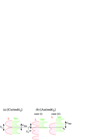
The two contrasting situations for large interactions are summarized in Fig. 5(d), where schematic representations of electron occupancies in the two cases are shown. In the case of [Au(tmdt)2], localized spins appear on the antibonding orbital of dimerized L sites. In contrast, in the case of [Cu(tmdt)2] spins appear on each of the L sites as well as of the M sites as a result of orbital mixing.
3.1 [Au(tmdt)2]
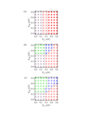
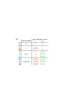
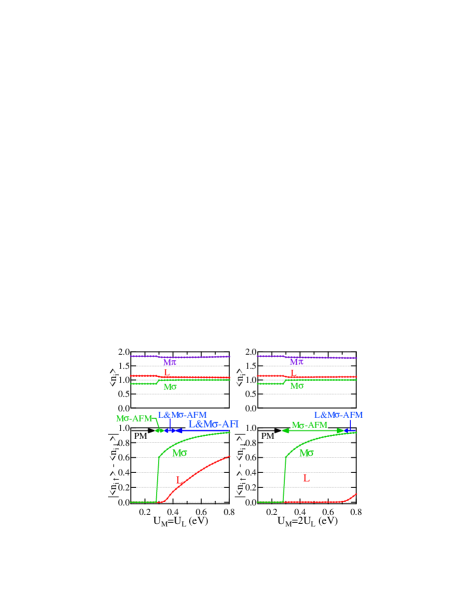
In Fig. 6, we show ground-state phase diagrams for three different parameter sets corresponding to [Au(tmdt)2]. Figures 6(a) and 6(b) are those with fitted results for the room- and low- structures, respectively, in Table 1. Besides them, to see the effect of the reduction in more explicitly, we artificially decrease it from its room- value as eV, while leaving the other room- parameters unchanged: This is shown in Fig. 6(c). The distinct states are indicated in the phase diagrams by different symbols summarized in Fig. 6(d), together with their magnetic ordering vectors. As can be seen there, the AF order on the L sites always has the pattern shown in Fig. 5(b) with . By the reduction in , we indeed find a crucial difference: The dimer-type AF insulating (AFI) state within the L orbital discussed above [filled symbol in Fig. 6(a)] stabilized in the wide range of parameters in the room- case is not seen, and different AF metallic (AFM) states appear in Figs. 6(b) and 6(c), owing to the mixing between the L and M orbitals.
In Fig. 7, we show the dependence of site occupation number for the three kinds of orbitals together with the spin moments on the L and M orbitals. Figures 7(a)-7(c) correspond to the cases in Figs. 6(a)-6(c), respectively. The right and left panels in Figs. 7(b) and 7(c) are data along different traces in the (, ) plane, i.e., for and , respectively.
3.1.1 Room-temperature structure
The phase diagram in Fig. 6(a) shows no dependence on ; this is because the M orbital is always nearly unoccupied, as shown in Fig. 7(a). As is increased, the system varies as PM AFM AFI states. Since only L sites possess magnetic moments, the magnetic phases are represented as L-AFM and L-AFI in Fig. 7(a).
These results are almost identical to the results in ref. \citenSeo_2008JPSJ, where the MF calculations were carried out for the three-band model based on {M, L} and assuming . This is consistent with the fact that the present results show an almost fully occupied M orbital playing no role and having no dependence on . As discussed there, the properties are governed by L orbitals. Their occupation number of 1.5 together with the rather strong dimerization are consistent with the fact that our results are analogous to the MF calculations on two-dimensional 1/4-filled Hubbard models with dimerization, e.g., as firstly performed on the model of -ET[37]. The existence of the AFM phase in between the AFI and PM phases is due to the imperfect nesting property of the Fermi surface, where small magnetic moments cannot produce a band splitting large enough to open up a gap on the whole Fermi surface. As long as the system is in the AFM phase, the spin moment on each site is less than 0.2 ; this is also the same as that in the three-band model. [18].
3.1.2 Low-temperature structure and reduced
The phase diagrams in Fig. 6(b) for the fitted results for the low- structure and in Fig. 6(c) for the room- values but with reduced share common features in their overall structure, but are very different from that in the room- case. Spin moments appear on M orbitals when is enlarged, however insulating states are not stabilized, at least, for eV; the whole phase diagrams show metallic states. The phase diagrams are devided into four regions: PM, L-AFM, magnetic metallic states with moments on M sites [either antiferromagnetic (M-AFM) or ferromagnetic (M-FM)], and those with moments on both orbitals [L&M-AFM or L&M-FM]. These are common for Figs. 6(b) and 6(c); therefore, the main variation from the room- structure to the low- structure can be captured by the reduction in . We note that the reduction in when the room- and low- values are compared is about 0.05 eV, while other parameters only slightly change; the phase diagram shows a marked change.
The L-AFM phase stabilized in the large-, small- region is the remnant of the L-AFI phase in the room- parameters. Its ordering vector is the same and the amplitude of magnetic moment is similar to that in the AFI phase in Fig. 6(a). For example, in the left panel of Figs. 7(b), it reaches 0.37 per site at eV. Nevertheless, the system does not turn into an insulating phase, which is due to orbital mixing: The occupation numbers are and for the low- parameters, and and for the reduced- case, which are noticeably shifted from the case of the room- parameters. Then this L-AFM state in the large- region can be considered as a ‘doped dimer-Mott insulator’ due to the mixing with the M orbital.
On the other hand, in the small-, large- region, the M-AFM or M-FM state is stabilized. L sites remain paramagnetic and the system is naturally metallic. The magnitude of the moment appearing on M sites is limited by its occupation number, as shown in Figs. 7(b) and 7(c), i.e., about 0.1-0.2. It is difficult to discuss the origin of each spin ordering vector for M sites, , within our limited supercell size, since its small filling factor would typically favor a longer periodicity. In fact, it takes different values delicately depending on the parameters. However, we consider that the region where spin moments appear is reasonable. Comparing the phase diagrams in Figs. 6(b) and (c), the latter has larger region of phases with moments on the M orbital, owing to the smaller and therefore the larger occupation number in M.
Even when we enter the region when both and are large where spin ordering on M and L sites coexist, the system still remains metallic. Here, the spin moment on L sites can be large similarly to that in the case of the L-AFM phase. For example, in the left panel of Figs. 7(c), it reaches 0.35-0.4 per site at eV. In this sense, this is also the remnant of the L-AFI phase in the room- parameters, stabilized at similar interaction parameters. As shown in Fig. 7(c), when the spin moment on L sites increases, that on the M orbital decreases, owing to the mismatch of their ordering vectors. This is in contrast with the case of Cu(tmdt)2, as we will see in the next subsection.
We note that, in the case of the low- parameters, there is a wide region where the ordering vector is , namely, the ferromagnetic (M-FM) or ferrimagnetic state when L sites also show spin moments (L&M-FM) is stabilized. This can be ascribed to the large density of state at , due to the lower edge of the 1D band from the M orbital [16]. In the room- structure, this edge situates just above , which becomes near it for the low- parameters. The states with also appears in the reduced- case [see Figs. 6(c) and 7(c)].
3.2 [Cu(tmdt)2]
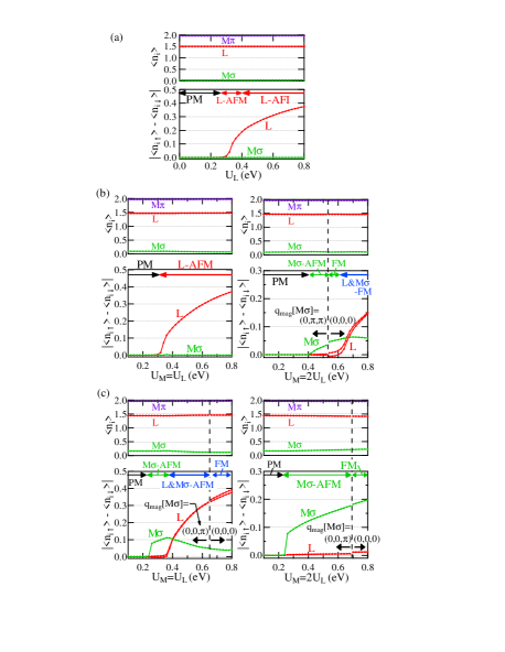
The MF ground-state phase diagram for [Cu(tmdt)2] is shown in Fig. 8, while the parameter dependences of orbital occupations and magnetic moments are shown in Fig. 9. Although the M orbital is off from the full occupation compared with those in the other cases (see Table 1), we find no contribution of it to the magnetic properties; therefore, we can set them aside again. The occupation numbers of the other two orbitals are now rather close to 1, i.e., 1/2-filling. Then, as discussed above, an AF insulating state with both M and L showing magnetic ordering (L&M-AFI) is seen to be stabilized in the region where both and are large. Its spin pattern is the staggered one as is shown in Fig. 5(c). As shown in Fig. 9(c), the spin moments on the L and M orbitals develop cooperatively as the interaction is enhanced.
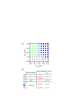
In the large-, small- region, on the other hand, the L-AFM state is stabilized, and vise versa, i.e., the M-AFM state is realized for the small-, large- region In these states, the spin ordering vector is the same as that in the L&M-AFI phase []; these states are continuously connected. However, they cannot open an insulating gap since, although the AF ordering provides a band splitting at in the magnetic orbital sector, the remaining orbital is paramagnetic with a Fermi surface. In other words, the spin ordering and band gap opening are orbital-selective. The critical value for the magnetic states is smaller for the M-AFM, consistent with the fact that M sites have smaller transfer integrals with a 1D structure than the L sites. As shown in Fig. 9, the magnetic moment on each site can be large, owing to the large filling factor near 1. In fact, the calculations show a jump in the charge density on each site across the PM AFM boundary (first order phase transition), which results in the occupation number for M and L to be closer to 1 in the magnetic phases, that is, 0.99 for M and 1.08 for L, than in the PM phase.
One point to note is that, although the phase diagram is mostly dominated by the state, we find many self-consistent solutions with very close MF energies in the region where M orbitals are magnetic. In these quasi-degenerate states, spin ordering vectors are of the form with or , namely, only the 2 periodicity is robust. This suggests that the spin exchange coupling between moments on M sites is essentially 1D, which is consistent with the fitted results in Table 1 where the A bond along [100] has the largest M-M transfer integral. This is also consistent with the first-principles calculations that compare different magnetic orderings [21]. On the other hand, the L orbital always orders with : the two-dimensional AF is stable at the MF level.
4 Discussion
In this section, we compare our MF results with experiments on magnetic ordering in this family, keeping in mind that, in the calculations, quantum fluctuations are neglected; additional effects of such fluctuations as well as the possible strong correlation effect can be speculated on top of the MF results. Discussions on [Cu(tmdt)2] is followed by that on [Au(tmdt)2], since in the former we can have a consistent explanation of the experiments. As for the latter, we present several possible scenarios for the magnetic phase transition in this compound, in light of considerations of its Cu analog.
4.1 [Cu(tmdt)2]
Let us give an explanation of the experimental results in [Cu(tmdt)2] based on our calculations, in association with the discussions in the literature [19, 20, 21]. The experiments show an insulating behavior in the resistivity, and the magnetic properties of a 1D Heisenberg spin system likely due to -MO, namely, the M orbital.
The insulating state in our MF calculations is realized for the L&M-AFI phase (Fig. 8) when both and are large. We can consider this state as a multiband Mott insulator where both L and M orbitals possess localized spins of effective each. In the MF calculation, this state is accompanied by a three-dimensional AF ordering. We can deduce the additional quantum effect as a spin singlet formation in the L network: the rather strong dimerization on B bonds can bring about a nonmagnetic ground state in the L subunit, as long as the other values are small enough. Then the active spin degree of freedom arises only in the M sector. It has a 1D character as discussed above, and therefore consistent with the Mott insulating behavior with 1D chains. This situation is schematically shown in Fig. 10(a).
Another scenario is that the system corresponds to the M-AFM phase in our MF phase diagram in the small- and large- region (considering the relation ), while other effects beyond our calculation bring about the insulating behavior. In this MF solution, roughly speaking, the magnetic ordering brings about a gap at for the M band, but the L bands remains metallic. This corresponds to the state found in the first-principles band calculation [21]. One possibility is that, since, in this state, locates in the middle of L bands, where the band overlap is small, a small perturbation might bring about a band gap. This is now a band insulator due to the dimerization in the L sector. Then the spin degree of freedom is only from the M orbital, again considered as a Mott insulator, showing the same magnetic behavior as above. The largest degree of dimerization in L sites among the cases listed in Table 1 is consistent with both pictures.
4.2 [Au(tmdt)2]
There have been puzzling experimental data for [Au(tmdt)2], as mentioned in § 1. Our MF results for the room- structure in § 3.1.1, which suggest that only L orbitals are magnetically active, lead to the same conclusion that we discussed previously [16, 17, 18], facing difficulties in explaining the experimental results. The main problems were as follows: (1) The AFM (spin-density-wave) state in the calculations shows a small magnetic moment, whereas when is increased to achieve a large moment state the system enters the AFI phase, i.e., the dimer-Mott insulator. The experimentally observed metallic ground state with a large magnetic moment could not be reconciled. (2) Discussions only involving the L sector are incompatible with the absence of a sign of phase transition in the resistivity at . Spin-density-wave states due to the nesting of the Fermi surface should result in a change in transport properties.
In clear contrast, on the other hand, the results of MF calculations in § 3.1.2, using the low- parameters [Figs. 6(b) and 7(b)] as well as the reduced values [Figs. 6(c) and 7(c)], show possible AFM states with larger magnetic moments. In these states, owing to the orbital mixing between L and M, AF ordering cannot open a gap at ; therefore, the system remains metallic. Such an involvement of multiorbitals also leads to possible explanations for the absence of anomaly at in the resistivity, suggesting that the magnetic and transport properties are carried by different degrees of freedom. Below, let us propose two possibilities on the basis of our results, considering the strong correlation effect in addition. We ascribe the regions where magnetic moments arise in our calculations as doped Mott insulating states, as discussed in § 3.1.2.
(i) {L: doped Mott insulator, M: PM}. This corresponds to the L-AFM state in our calculations. The L orbital forms a dimer-Mott insulating state but doped with holes, which are provided from the M orbital remaining in a PM state. The Mott gap is due to the effective on-dimer Coulomb interaction, as indicated by in Fig. 10(b) [case (i)].
(ii) {L: PM, M: doped Mott insulator}. In the MF calculation, in the large-, small region, M-AFM/FM states are stabilized. If a similar picture of the Mott insulating nature in scenario (i) is applied, this results in a situation shown in Fig. 10(b) [case (ii)]. The Mott gap formation in the M sector is adopted from the discussions on [Cu(tmdt)2].
In both cases, the doped Mott insulating character will generate magnetism, while there exist carriers unchanged upon magnetic ordering. In the MF phases corresponding to case (i), large spin moments appear on L sites, whereas its ordering is expected to affect the transport properties since L bands are mainly responsible for the conduction. On the other hand, case (ii) is favorable in the sense that L bands are paramagnetic and carries the charge transport, and then M sites are responsible for magnetism; such a picture has been proposed on the basis of experimental considerations [38]. The weaker dimerization in L sites than in the Cu analog obtained in our estimated transfer integrals may be a factor for stabilizing such a metallic L system. However, in our calculation the magnetic moment on M is small, limited by its occupation, i.e., the small electron-doping level. This is not in agreement with the argument. With enhanced mixing between the two levels, approaching the situation in [Cu(tmdt)2] is expected to bring about a possible reconciliation with the experimental results, although within our estimation of parameters such a prominent mixing is not achieved. Future works including that on the strong correlation effect are needed for further investigating this possibility.
Finally, the observed peculiarly high is difficult to discuss from our calculation only for the ground state, and the evaluation of transition temperature at the MF level is usually not reliable for comparison with experiments, especially when the strong correlation is involved. The low dimensionality in both L and M orbitals when considering intraorbital transfer integrals is apparently incompatible with such a high , considering the fact that the energy scale is similar to those of other molecular conductors showing lower transition temperatures for magnetic ordering in general. One possibility is that doped carriers in mixed orbitals effectively make the spin-spin interaction large, especially even in the -direction where the original parameters among the L and M orbitals are small, making the system three-dimensionally coupled. Then the low-dimensionality embedded in each orbital can be released to increase the critical temperature.
5 Summary
We have constructed effective models of single-component molecular conductors [(tmdt)2] ( = Ni, Au, and Cu) showing a multiorbital nature. Tight-binding parameters are obtained by a fitting to first-principles band structures. The fragment molecular orbital picture leads us to a systematic view of this family: the interplay between a characteristic anisotropic electronic network and the orbital energy difference can tune electronic states using a different choice of , particularly that between the -type and -type orbitals. By taking into account the Coulomb interaction, we discussed, for [Au(tmdt)2] and [Cu(tmdt)2], the mean-field phase diagrams and magnetic solutions of our effective model. In the former compound, we suggest that the mixing between the two orbitals can play a key role in resolving their puzzling experimental results. On the other hand, in the latter, the existence of a multiorbital Mott insulator is suggested, which is consistent with the experimental results. Both of these cases are distinctive examples of molecular systems.
Acknowledgments
We thank K. Kanoda, A. Kobayashi, H. Kobayashi, R. Takagi, and M. Tsuchiizu for discussions and suggestions. This work was supported by Grant-in-Aid for Scientific Research (Nos. 20110003, 20110004, and 24108511) from MEXT.
References
- [1] H. Tanaka, Y. Okano, H. Kobayashi, W. Suzuki, and A. Kobayashi: Science 291 (2001) 285.
- [2] A. Kobayashi, E. Fujiwara, and H. Kobayashi: Chem. Rev. 104 (2004) 5243.
- [3] H. Seo, C. Hotta, and H. Fukuyama: Chem. Rev. 104 (2004) 5005.
- [4] Special Topics on Organic Conductors, J. Phys. Soc. Jpn. 75 (2006) 051001-051016.
- [5] A. Kobayashi, H. Tanaka, and H. Kobayashi: J. Mater. Chem. 11 (2001) 2078.
- [6] E. Canadell, I. E. I. Rachidi, S. Ravy, J. P. Pouget, L. Brossard, and J. P. Legros: J. Phys. (Paris) 50 (1989) 2967.
- [7] R. Kato: Chem. Rev. 104 (2004) 5319.
- [8] In this paper, [(tmdt)2] and (tmdt)2 are used to express the crystals and molecules, respectively.
- [9] H. Tanaka, M. Tokumoto, S. Ishibashi, D. Graf, E. S. Choi, J. S. Brooks, S. Yasuzuka, Y. Okano, H. Kobayashi, and A. Kobayashi: J. Am. Chem. Soc. 126 (2004) 10518.
- [10] C. Rovira, J. J. Novoa, J.-L. Mozos, P. Ordejón, and E. Canadell: Phys. Rev. B 65 (2002) 081104.
- [11] S. Yasuzuka, H. Tanaka, M. Tokumoto, D. Graf, E. S. Choi, J. S. Brooks, H. Kobayashi, and A. Kobayashi: J. Phys. Soc. Jpn. 77 (2008) 034709.
- [12] W. Suzuki, E. Fujiwara, A. Kobayashi, Y. Fujishiro, E. Nishibori, M. Takata, M. Sakata, H. Fujiwara, and H. Kobayashi: J. Am. Chem. Soc. 125 (2003) 1486.
- [13] B. Zhou, M. Shimamura, E. Fujiwara, A. Kobayashi, T. Higashi, E. Nishibori, M. Sakata, H. B. Cui, K. Takahashi, and H. Kobayashi: J. Am. Chem. Soc. 128 (2006) 3872.
- [14] Y. Hara, K. Miyagawa, K. Kanoda, M. Shimamura, B. Zhou, A. Kobayashi, and H. Kobayashi: J. Phys. Soc. Jpn. 77 (2008) 053706.
- [15] H. Tanaka, S. Hara, M. Tokumoto, A. Kobayashi, and H. Kobayashi: Chem. Lett. 36 (2007) 1006.
- [16] S. Ishibashi, H. Tanaka, M. Kohyama, M. Tokumoto, A. Kobayashi, H. Kobayashi, and K. Terakura: J. Phys. Soc. Jpn. 74 (2005) 843.
- [17] S. Ishibashi, K. Terakura, and A. Kobayashi: J. Phys. Soc. Jpn. 77 (2008) 024702.
- [18] H. Seo, S. Ishibashi, Y. Okano, H. Kobayashi, A. Kobayashi, H. Fukuyama, and K. Terakura: J. Phys. Soc. Jpn. 77 (2008) 023714.
- [19] B. Zhou, H. Yajima, A. Kobayashi, Y. Okano, H. Tanaka, T. Kumashiro, E. Nishibori, H. Sawa, and H. Kobayashi: Inorg. Chem. 49 (2010) 6740.
- [20] R. Takagi, K. Miyagawa, K. Kanoda, B. Zhou, A. Kobayashi, and H. Kobayashi: Phys. Rev. B 85 (2012) 184424.
- [21] S. Ishibashi and K. Terakura: Crystals 2 (2012), 1210.
- [22] B. Zhou, A. Kobayashi, Y. Okano, H. B. Cui, D. Graf, J. S. Brooks, T. Nakashima, S. Aoyagi, E. Nishibori, M. Sakata, and H. Kobayashi: Inorg. Chem. 48 (2009) 10151.
- [23] H. Seo, J. Merino, H. Yoshioka, and M. Ogata: J. Phys. Soc. Jpn. 75 (2006) 051009.
- [24] M.-L. Bonnet, V. Robert, M. Tsuchiizu, Y. Omori, and Y. Suzumura: J. Chem. Phys. 132 (2010) 214705.
- [25] M. Tsuchiizu, Y. Omori, Y. Suzumura, M.-L. Bonnet, V. Robert, S. Ishibashi, and H. Seo: J. Phys. Soc. Jpn. 80 (2011) 013703.
- [26] M. Tsuchiizu, Y. Omori, Y. Suzumura, M.-L. Bonnet, and V. Robert, J. Chem. Phys. 136 (2012) 044519.
- [27] K. Kitaura, E. Ikeo, T. Asada, T. Nakano, and M. Uebayasi: Chem. Phys. Lett. 313 (1999) 701.
- [28] S. Tsuneyuki, T. Kobori, K. Akagi, K. Sodeyama, K. Terakura, and H. Fukuyama: Chem. Phys. Lett. 476 (2009) 104.
- [29] http://www.qmas.jp.
- [30] P. E. Blchl: Phys. Rev. B 50 (1994) 17953.
- [31] J. P. Predew, K. Burke, and M. Ernzerhof: Phys. Rev. Lett 77 (1996) 3865.
- [32] In ref. \citenSeo_2008JPSJ, we called the M and M orbitals the M orbitals; when needed, they were distinguished as M() and M(), respectively.
- [33] We have considered the effect of Hund coupling in the MF calculations, but did not find any qualitative difference in the parameter range we investigated (), and therefore omitted it in this paper.
- [34] T. Misawa, K. Nakamura, and M. Imada: J. Phys. Soc. Jpn. 80 (2011) 023704.
- [35] The results for the Ni and Au compounds are consistent with the three-band fits [18]; however, some differences are seen in their values, partly because of the inclusion of one more orbital for each compound, and also because of our reduction of the number of finite in the fitting, to obtain numerically reliable results. For example, the intramolecular L1-L2 transfer integral for Au(tmdt)2 in this work is noticeably smaller than that in ref. \citenSeo_2008JPSJ; this can be understood as the value in ref. \citenSeo_2008JPSJ effectively including the L1-M-L2 process; we independently treat these parameters here. However, the small values can vary depending on the details of the fitting process. An analysis using Wannier functions is now under way.
- [36] We have investigated different parameter sets such as , but we did not find any qualitative difference. The M orbital is always nearly occupied, and the -term does not play a role in stabilizing different states.
- [37] H. Kino and H. Fukuyama: J. Phys. Soc. Jpn. 64 (1995) 2726.
- [38] R. Takagi and K. Kanoda: private communications.