Spontaneous Emission Control in a Tunable Hybrid Photonic System
Abstract
We experimentally demonstrate control of the rate of spontaneous emission in a tunable hybrid photonic system that consists of two canonical building blocks for spontaneous emission control, an optical antenna and a mirror, each providing a modification of the local density of optical states (LDOS). We couple fluorophores to a plasmonic antenna to create a superemitter with an enhanced decay rate. In a superemitter analog of the seminal Drexhage experiment we probe the LDOS of a nanomechanically approached mirror. Due to the electrodynamic interaction of the antenna with its own mirror image the superemitter traces the inverse LDOS of the mirror, in stark contrast to a bare source, whose decay rate is proportional to the mirror LDOS.
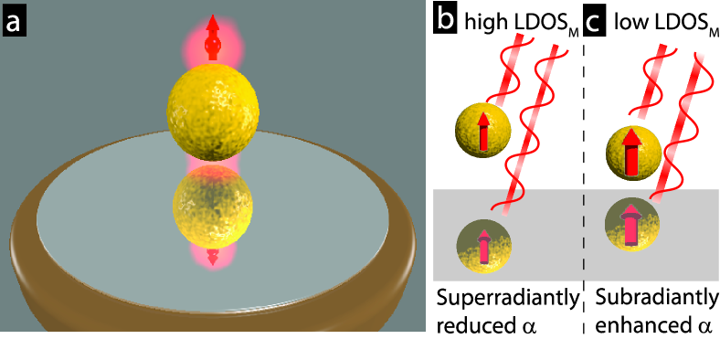
The study of light-matter interaction is a cornerstone of contemporary physics. According to Fermi’s golden rule the rate of spontaneous emission of light can be controlled through engineering of photonic modes Novotny and Hecht (2006). In a seminal experiment Drexhage modified the decay rate of fluorophores by varying their distance to a mirror Drexhage (1970). Already in 1946 Purcell had suggested to boost the decay rate of a source by coupling it to a resonant cavity Purcell (1946). Both Drexhage’s and Purcell’s works are nowadays discussed in terms of the local density of optical states (LDOS) a quantity governing spontaneous emission, thermal radiation, and vacuum mediated forces Novotny and Hecht (2006). A rich toolbox of photonic systems to control various aspects of spontaneous emission has been established, including cavities Vahala (2005), mirrors Snoeks et al. (1995); Buchler et al. (2005) and photonic crystals Noda et al. (2007) that all shape the LDOS on a wavelength scale. Length scales even smaller than the wavelength are the realm of nanophotonics Novotny and Hecht (2006) whose prototypical building block for spontaneous-emission control is the optical antenna, which exploits plasmonic resonances of metal nanoparticles Novotny and van Hulst (2011). By coupling a source of spontaneous emission to such a nano-antenna, a ‘superemitter’ Farahani et al. (2005) retaining the dipolar nature of the source yet exhibiting a boosted decay rate can be created Kühn et al. (2006). Currently, nanophotonics is combining and integrating these functional units into ‘hybrid photonic systems’ in order to boost figures of merit by embedding nanoplasmonic elements in cavities, stratified media or photonic crystals Benson (2011); Chen et al. (2012). Importantly, in such a photonic hybrid the building blocks are expected to interact with each other, such that the of the hybrid emerges from the respective LDOS of the individual building blocks in a non-trivial fashion Frimmer and Koenderink (2012). Consider a superemitter in front of a mirror, as sketched in Fig. 1(a), where the mirror represents a background system in which the superemitter is immersed. In this superemitter-equivalent of the classic Drexhage experiment a nano-antenna provides a rate enhancement to a fluorophore, e.g. a molecule. While the approaching mirror itself certainly provides an enhancement to the source, the antenna particle will interact with its mirror image, such that the mirror clearly not only acts on the source itself but furthermore can effectively modify the antenna. Therefore, a tunable photonic background system should offer a route to dynamically mould the properties of an optical antenna and thereby the rate enhancement it provides to a spontaneous emitter. However, the emergence of such a hybrid photonic LDOS from the individual LDOS of the constituents has never been unraveled to date.
This Letter experimentally demonstrates the dynamic control of the rate enhancement provided by an optical antenna to a spontaneous emitter in a hybrid photonic system. By nanomechanically approaching a metallic mirror to the source-antenna ensemble we perform the superemitter equivalent of the classic Drexhage experiment. We find that the superemitter probes the inverse of the mirror which is caused by the strong interaction between the optical antenna and its own mirror image.
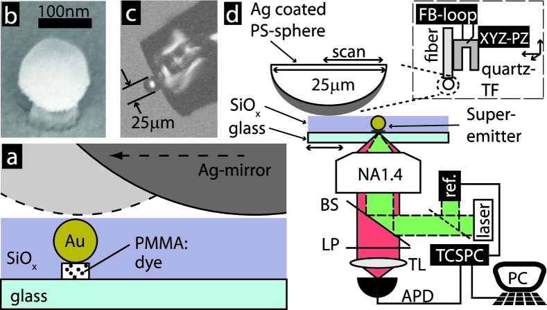
For our experiments we assembled superemitters [see sketch in Fig. 2(a)] by co-localizing fluorescing dye molecules with near-unity quantum yield (Bodipy TR, Invitrogen) with strongly scattering Au colloids (diameter 100 nm, BBInternational). A dye-doped PMMA layer (60 nm thickness) is spin coated on a glass cover slip Frimmer et al. (2012) onto which Au-colloids in solution are spin coated. An oxygen plasma removes PMMA and embedded fluorophores from the sample surface, except where the Au particle acts as an etch mask Sorger et al. (2011). As a result, we obtain isolated Au particles residing on dye-doped PMMA pedestals [diameter ca. 70 nm, see Fig. 2(b)]. We estimate the pedestal to contain several hundred dye molecules. The size of the pedestal renders the effect of quenching negligible, which only plays a role at emitter-metal distances 10 nm Anger et al. (2006). Finally, we cover the sample with a layer of about 120 nm spin-on glass (FOX-14, Dow Corning) for mechanical protection.
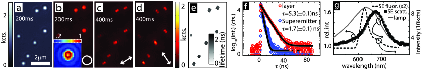
We characterize the superemitters optically in the setup reported in Ref. Frimmer et al., 2011 and sketched in Fig. 2(d). Under white light illumination the Au particles appear as bright scatterers on a CCD camera, as shown in Fig. 3(a). Under epi-illumination by a circularly polarized pump laser (532 nm, repetition rate 10 MHz, pulse width 10 ps) the fluorescence image of the region in Fig. 3(a) appears as shown in Fig. 3(b). Clearly, fluorescence emerges where scatterers are located. Since the molecules are immobilized under the Au particle we expect that the dipole moment induced in the optical antenna, which dominates emission of the superemitter, is oriented along the optical axis Taminiau et al. (2008). Accordingly, in fluorescence, superemitters appear as donut-shaped patterns on the CCD [see inset of Fig. 3(b)] Lieb et al. (2004). Furthermore, filtering the signal that led to Fig. 3(b) with a linear polarizer in the detection path yields Fig. 3(c), which exhibits the expected double-lobed pattern Lieb et al. (2004), which is furthermore practically unchanged in intensity and follows the polarizer axis when the analyzer is rotated [see Fig. 3(d)]. To characterize the decay rate of our superemitters Fig. 3(e) shows a fluorescence lifetime image of the area investigated for Figs. 3(a-d), where we have clamped the lifetime value of pixels holding less than 1000 events to zero. The distribution of lifetimes exhibited by the superemitters ranges from about 1.5 to 2 ns. An example for the decay behavior of a typical superemitter is shown in Fig. 3(f). The decay of the superemitter (blue diamonds) is fitted well with a single exponential with time constant 1.7 ns. To judge the enhancement provided by the Au particle the superemitter lifetime has to be compared to the lifetime of the dye molecules in absence of the antenna. To this end, we measure the decay in a reference section of the sample where no Au particles are present and which has been protected from the plasma etch. The bare dye molecules decay single exponentially with time constant 5.3 ns, shown as the open circles in Fig. 3(f).
The observed rate enhancement is a result of the plasmonic resonance of the Au nanoparticle Kühn et al. (2006); Mertens et al. (2007). To characterize the spectral matching of emitter and antenna we analyze the emission spectrum of the superemitters, shown as the dashed line in Fig. 3(g). The superemitter emission peaks around 620 nm and is broadened by a shoulder to span up to about 700 nm in close resemblance to the spectrum of the incorporated dye Johnson and Spence (2010). To characterize the antenna particle we show a typical superemitter scattering spectrum as the black squares in Fig. 3(g), where the spectrum of the used white-light source [grey line] has been normalized out. The particle’s scattering spectrum [black squares in Fig. 3(g)] exhibits a resonant line-shape, peaking around 665 nm and spanning a width of about 70 nm, while well overlapping the superemitter emission spectrum.
We now turn to our nanomechanical version of Drexhage’s experiment Drexhage (1970) whose implementation is inspired by the method developed by Buchler et al. Buchler et al. (2005) and relies on moving a spherical micromirror attached to a scanning probe Frimmer et al. (2012). As long as the diameter of the spherical mirror largely exceeds its distance to the source it serves as a good approximation of a flat mirror. Our scheme of changing the distance between a fluorophore and the mirror is illustrated in Fig. 2(a). The fluorescing source is fixed in a substrate while a large spherical mirror with a diameter of m is laterally moved across the sample surface. The mirror-sample distance is kept constant at ca. 5 nm with a shear-force feedback loop Novotny and Hecht (2006). In Fig. 2(a) two positions of the mirror with respect to a superemitter are shown to illustrate the principle of changing the emitter-mirror distance. The micromirror (a polystyrene bead covered with a 400 nm evaporated Ag layer) is glued to a cleaved optical fiber as shown in Fig. 2(c). The optical fiber is then glued to a quartz tuning fork, as sketched in Fig. 2(d, inset). Measurements on single emitters have confirmed that our method indeed exactly replicates Drexhage’s calibrated LDOS experiment Frimmer et al. (2012).
To perform the superemitter-equivalent of Drexhage’s experiment we combine our two methods to control spontaneous emission and approach the mirror to a superemitter, thereby dynamically tuning the LDOS experienced by the source-antenna assembly. To this end, we raster-scan our micromirror over a superemitter while continuously measuring its lifetime. As a result, we obtain the decay rate of the superemitter as a function of mirror-sample distance, shown as the black squares in Fig. 4. There is a clear variation visible in the decay rate as a function of mirror-sample separation. Note that this variation is due to the LDOS modification provided by the mirror on top of the three-fold enhancement provided by the optical antenna.
To model our experiments, we consider an air layer sandwiched between two semi-infinite half-spaces [see sketch in inset of Fig. 4], the upper one being Ag ( at 620 nm, measured by ellipsometry on an Ag film on a Si substrate), the lower one being glass () and unity quantum yield of the emitters Frimmer et al. (2012). We furthermore take into account that our superemitters are strongly polarized along the optical axis as established from Figs. 3(b-d). We therefore consider an emitter oriented perpendicularly to the interface and located at a fixed depth of 123 nm in the glass substrate as sketched in the inset of Fig. 4. The optical antenna is described in a dipole model as a polarizable sphere of 100 nm diameter whose center is located 53 nm into the glass substrate 111 The polarizability of the antenna particle is described in a Drude model with characteristic frequency and damping rate to match it to the scattering spectrum in Fig. 3(g).. Our model is fully analytical and electrodynamic, taking into account the full multiple-scattering process between the antenna and the double interface Frimmer and Koenderink (2012).
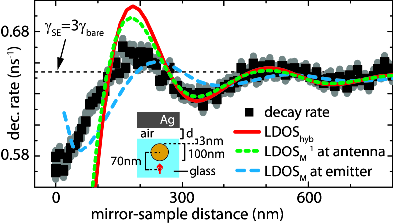
The red solid line in Fig. 4 is the calculated decay-rate enhancement experienced by the source coupled to the polarizable particle in front of the mirror (scaled with the antenna-enhanced decay rate of the source) as a function of air-gap thickness. The calculated hybrid enhancement is in excellent quantitative agreement with the measured data for mirror-sample distances larger than ca. 280 nm. At distances smaller than 280 nm there is good qualitative agreement between measurement and calculation while the measured decay-rate modifications are smaller than those theoretically predicted. We also plot the inverse of the mirror at the position of the antenna particle (scaled with the antenna-enhanced decay rate of the source) as a function of mirror-sample separation as the green dotted line in Fig. 4. Clearly, the enhancement calculated for the superemitter [red solid line in Fig. 4] closely follows the inverse in front of the mirror. The inverse proportionality of the superemitter enhancement factor to the mirror reflects that the antenna, which dominates the decay of the superemitter, behaves very differently from a quantum emitter, whose decay rate is proportional to the LDOS. This stark contrast is a result of the antenna being a strong scatterer driven by the source and subjected to its own scattered field Frimmer and Koenderink (2012) as opposed to a quantum emitter corresponding to a constant current source in a classical treatment Novotny and Hecht (2006). At positions of enhanced mirror the scattered field, reflected from the mirror and arriving back at the antenna with a phase difference, effectively depolarizes the antenna. More intuitively stated, as illustrated in Figs. 1(b,c), when the mirror is high (low) the scattered field of the antenna interferes constructively (destructively) with that of its own mirror image, effectively forming a super- (sub-)radiant hybrid plasmonic mode Prodan et al. (2003); Buchler et al. (2005). For a subradiant mode, the suppressed radiative damping results in an enhanced antenna resonance strength. Accordingly, the decay rate of a superemitter can be boosted beyond by embedding it in a background system with reduced LDOS, ideally approaching a photonic bandgap Noda et al. (2007). This counterintuitive inverse LDOS effect is generic for any antenna whose damping rate is mainly radiative Frimmer and Koenderink (2012), i.e., for any large antenna with scattering cross section close to the upper bound known as the unitary limit.
Finally, to exclude that the measured variation of decay rate is the result of the dye molecules themselves experiencing the of the approaching mirror we also plot (scaled with the antenna-enhanced decay rate of the source) at the position of the source as the blue dashed line in Fig. 4. Clearly, the at the source itself is incommensurable with the measured data. Figure 4 therefore represents the experimental confirmation that an increased background LDOS indeed reduces the enhancement experienced by a source coupled to a strongly scattering antenna. Regarding the discrepancy between the calculation and the measurement for very small mirror-sample distances in Fig. 4 we speculate that the finite size of our antenna particle starts to play a role on such small length scales. This regime offers the exciting prospect of engineering higher-order multipolar analogues of the LDOS Chen et al. (2012); Andersen et al. (2011).
In conclusion, we have coupled spontaneous emitters confined to a subwavelength volume to an optical antenna, creating a superemitter exhibiting a decay-rate enhancement of three. We actively tuned the rate enhancement provided by the antenna by nanomechanically approaching a mirror to the superemitter. Importantly, we found that the decay-rate enhancement experienced by the source in the superemitter varies in proportion to the inverse LDOS of the mirror Frimmer and Koenderink (2012) as a result of the antenna effectively hybridizing with its own mirror image. Our system is inherently broadband, since the resonance of the optical antenna is broad and the mirror also has no characteristic resonance. It will be most interesting to extend our study to emitters coupled to both deep-subwavelength optical antennas and super-wavelength resonators, like microspheres or microtoroids Vahala (2005), which can be manipulated nanomechanically as well Mazzei et al. (2007). Furthermore, our results shed new light on approaches to efficiently interface single emitters via optical antennas with microresonators Xiao et al. (2012) or waveguides Bernal Arango et al. (2012).
Acknowledgements.
This work is part of the research program of the “Stichting voor Fundamenteel Onderzoek der Materie (FOM)”, which is financially supported by the “Nederlandse Organisatie voor Wetenschappelijk Onderzoek (NWO)”. AFK gratefully acknowledges an NWO-Vidi grant for financial support.References
- Novotny and Hecht (2006) L. Novotny and B. Hecht, Principles of Nano-Optics (Cambridge University Press, Cambridge, 2006).
- Drexhage (1970) K. H. Drexhage, J. of Lumin. 1-2, 693 (1970).
- Purcell (1946) E. M. Purcell, Phys. Rev. 69, 681 (1946).
- Vahala (2005) K. Vahala, ed., Optical Microcavities (Advanced Series in Applied Physics, Vol. 5) (World Scientific, Singapore, 2005).
- Snoeks et al. (1995) E. Snoeks, A. Lagendijk, and A. Polman, Phys. Rev. Lett. 74, 2459 (1995).
- Buchler et al. (2005) B. C. Buchler, T. Kalkbrenner, C. Hettich, and V. Sandoghdar, Phys. Rev. Lett. 95, 063003 (2005).
- Noda et al. (2007) S. Noda, M. Fujita, and T. Asano, Nature Photon. 1, 449 (2007).
- Novotny and van Hulst (2011) L. Novotny and N. van Hulst, Nature Photon. 5, 83 (2011).
- Farahani et al. (2005) J. N. Farahani, D. W. Pohl, H.-J. Eisler, and B. Hecht, Phys. Rev. Lett. 95, 017402 (2005).
- Kühn et al. (2006) S. Kühn, U. Håkanson, L. Rogobete, and V. Sandoghdar, Phys. Rev. Lett. 97, 017402 (2006).
- Benson (2011) O. Benson, Nature 480, 193 (2011).
- Chen et al. (2012) X.-W. Chen, M. Agio, and V. Sandoghdar, Phys. Rev. Lett. 108, 233001 (2012).
- Frimmer and Koenderink (2012) M. Frimmer and A. F. Koenderink, Phys. Rev. B 86, 235428 (2012).
- Frimmer et al. (2012) M. Frimmer, A. Mohtashami, and A. F. Koenderink, arXiv:1212.5081 (2012).
- Sorger et al. (2011) V. J. Sorger, N. Pholchai, E. Cubukcu, R. F. Oulton, P. Kolchin, C. Borschel, M. Gnauck, C. Ronning, and X. Zhang, Nano Lett. 11, 4907 (2011).
- Anger et al. (2006) P. Anger, P. Bharadwaj, and L. Novotny, Phys. Rev. Lett. 96, 113002 (2006).
- Frimmer et al. (2011) M. Frimmer, Y. Chen, and A. F. Koenderink, Phys. Rev. Lett. 107, 123602 (2011).
- Taminiau et al. (2008) T. H. Taminiau, F. D. Stefani, and N. F. van Hulst, New J. Phys. 10, 105005 (2008).
- Lieb et al. (2004) M. A. Lieb, J. M. Zavislan, and L. Novotny, J. Opt. Soc. Am. B 21, 1210 (2004).
- Mertens et al. (2007) H. Mertens, A. F. Koenderink, and A. Polman, Phys. Rev. B 76, 115123 (2007).
- Johnson and Spence (2010) I. Johnson and M. T. Spence, eds., Molecular Probes Handbook, 11th Edition (Invitrogen, 2010).
- Note (1) The polarizability of the antenna particle is described in a Drude model with characteristic frequency and damping rate to match it to the scattering spectrum in Fig. 3(g).
- Prodan et al. (2003) E. Prodan, C. Radloff, N. J. Halas, and P. Nordlander, Science 302, 419 (2003).
- Andersen et al. (2011) M. L. Andersen, S. Stobbe, A. S. Sørensen, and P. Lodahl, Nature Phys. 7, 215 (2011).
- Mazzei et al. (2007) A. Mazzei, S. Götzinger, L. de S. Menezes, G. Zumofen, O. Benson, and V. Sandoghdar, Phys. Rev. Lett. 99, 173603 (2007).
- Xiao et al. (2012) Y.-F. Xiao, Y.-C. Liu, B.-B. Li, Y.-L. Chen, Y. Li, and Q. Gong, Phys. Rev. A 85, 031805 (2012).
- Bernal Arango et al. (2012) F. Bernal Arango, A. Kwadrin, and A. Koenderink, ACS nano (2012).