Concurrent object-oriented development with behavioral design patterns
Abstract
The development of concurrent applications is challenging because of the complexity of concurrent designs and the hazards of concurrent programming. Architectural modeling using the Unified Modeling Language (UML) can support the development process, but the problem of mapping the model to a concurrent implementation remains. This paper addresses this problem by defining a scheme to map concurrent UML designs to a concurrent object-oriented program. Using the COMET method for the architectural design of concurrent object-oriented systems, each component and connector is annotated with a stereotype indicating its behavioral design pattern. For each of these patterns, a reference implementation is provided using SCOOP, a concurrent object-oriented programming model. We evaluate this development process using a case study of an ATM system, obtaining a fully functional implementation based on the systematic mapping of the individual patterns. Given the strong execution guarantees of the SCOOP model, which is free of data races by construction, this development method eliminates a source of intricate concurrent programming errors.
1 Introduction
Writing concurrent applications is no longer a task for specialist programmers but has become a rather common development task in the age of multicore computing. Both the complexity of concurrent software architectures and the hazards associated with concurrent programming, such as data races and deadlocks, make this task a difficult one.
For concurrent object-oriented applications, support for the architectural design of the concurrent software is fortunately available. Standard notations, such as the Unified Modeling Language (UML), can provide such support when used with a method for developing concurrent applications, such as COMET [7]. The remaining difficulty is the mapping of the concurrent object-oriented model to an implementation that avoids common concurrency pitfalls.
This paper describes a development method that starts with a concurrent UML design annotated with behavioral stereotypes and maps the design systematically to an implementation of the system that is guaranteed to be data-race free. Each architectural component in the UML model is given a behavioral role, based on the COMET object structuring criteria. For each of COMET’s component and connector types we define a mapping to an implementation in SCOOP (Simple Concurrent Object-Oriented Programming) [9, 12], a concurrent object-oriented programming model. Choosing this model over others has the benefit of strong execution guarantees: by construction, the model is free of data races; furthermore, mechanisms for avoiding deadlocks have been defined [22]. The mapping of an entire architectural model to a SCOOP program is based on the mappings of the individual design artifacts and their composition.
To evaluate the approach, the development process is applied to a case study of an ATM system that covers all important connector and component patterns, obtaining a fully functional implementation of the system.
The remainder of the paper is structured as follows. Section 2 describes behavioral design patterns of the COMET method in UML. After an overview of the SCOOP concurrency model in Section 3, the implementation of the design patterns is described in Section 4. Section 5 presents the case study. Section 6 presents a survey of related work, and Section 7 draws conclusions.
2 Behavioral design patterns
The concurrent software architecture of a system is best understood by considering the dynamic characteristics of the system, which is why this paper focuses on behavioral design patterns. Behavioral design patterns used by the COMET method [7, 8] address design issues in concurrent and distributed applications. There are two main categories of behavioral design patterns. Structural patterns address the component structure of the concurrent software architecture. Communication patterns address the message communication between the concurrent components.
2.1 Structural patterns and component design
Structural patterns address concurrent component design. To assist the designer, concurrent component structuring criteria are provided. Each component is depicted from two different perspectives, its role in the application and the behavioral nature of its concurrency. Models of the design use UML stereotypes to depict the structuring decisions made by the designer. The stereotype depicts the component’s role criterion, which describes the component’s function in the application such as I/O or control. A UML constraint is used to describe the type of concurrency of the component, which is based on how the component is activated. For example, a concurrent I/O component could be activated by an external event or a periodic event, whereas an entity component is passive and access to it is mutually exclusive or by means of multiple readers and writers. Components are categorized using a component stereotype classification hierarchy as shown in Figure 1.
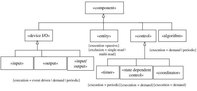
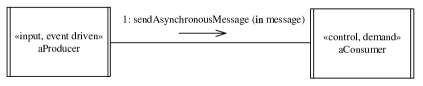
An event driven I/O component interfaces to an event (interrupt) driven I/O device and is awakened by an external interrupt from the device. A demand-driven algorithm or control component is awakened by a message sent by a producer component. A periodic component is activated by a timer event at regular intervals. Figure 2 depicts an event driven input component communicating with a demand-driven control component. The stereotypes for the producer and consumer depict the component role (e.g., control) followed by the type of concurrency (e.g., demand). Alternatively, separate stereotypes could be used to depict the component role and the type of concurrency, which is supported by UML 2 [8] but not by all UML tools.
2.2 Communication patterns and connector design
Communication between concurrent components is a particularly important design issue because, unlike sequential systems in which call/return is the only pattern of communication between sequential components, there are many different ways in which concurrent components can communicate with each other. Communication patterns describe the different types of message communication between the concurrent components of the software architecture. In both distributed and non-distributed applications, communication patterns include asynchronous communication and synchronous communication with or without reply. Other communication patterns are exclusively for distributed systems, including brokered communication, event-based communication, and transaction-based communication.
Using the component/connector paradigm, a connector can be designed for each communication pattern to encapsulate the details of the communication mechanism. The message buffer and message buffer and reply connectors implement the synchronous communication pattern without respectively with reply; the message queue and message queue and callback connectors implement the corresponding asynchronous communication patterns. These connectors can also be categorized using a stereotype classification hierarchy as shown in Figure 3.
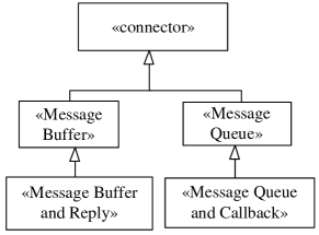
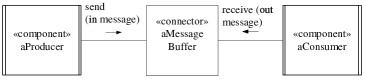
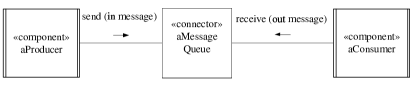
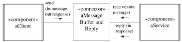
Figure 4a depicts a synchronous communication without reply pattern, in which the concurrent producer component sends a message to a concurrent consumer component via a message buffer connector, and waits for the consumer to accept the message. Figure 4b depicts an asynchronous message communication pattern in which a producer communicates with a consumer through a message queue connector that encapsulates the details of the asynchronous communication by: (1) adding a message from the producer to a FIFO message queue and only suspending the producer if the queue is full (2) returning a message to a consumer or suspending the consumer if the queue is empty. Figure 4c depicts a synchronous communication with reply pattern in which the client component sends a message to a service component and waits for the reply via a message buffer and reply connector. Figure 4d depicts an asynchronous communication with reply pattern in which the client sends a message to a service via a message queue and callback connector, continues executing and later receives the service response from the connector. In this pattern, the client needs to provide an id or callback handle at which the response is returned, as shown in Figure 4d. Note that the callback response is handled asynchronously, and hence differently from the synchronous communication with reply pattern. For this reason, the response is named a callback to distinguish it from a synchronous reply.

3 SCOOP
The main idea of SCOOP [9, 12, 10] is to simplify the writing of correct concurrent programs, by allowing developers to use familiar concepts from object-oriented programming while protecting them from common concurrency errors such as data races. Empirical evidence supports the claim that SCOOP indeed simplifies reasoning about concurrent programs as opposed to more established models [11]. SCOOP has been developed on top of Eiffel, an object-oriented programming language; however, SCOOP’s concurrency model can be applied to other object-oriented programming languages, for example to Java [21].
In SCOOP, every object is associated for its lifetime with a processor, called its handler. A processor is an autonomous thread of control capable of executing actions on objects. An object’s class describes the possible actions as features. A variable x belonging to a processor can point to an object with the same handler (non-separate object), or to an object on another processor (separate object). In the first case, a feature call x.f is non-separate: the handler of x executes the feature synchronously. In this context, x is called the target of the feature call. In the second case, the feature call is separate: the handler of x, i.e., the supplier, executes the call asynchronously on behalf of the requester, i.e., the client. The possibility of asynchronous calls is the main source of concurrent execution.
The producer-consumer problem serves as a simple illustration of these ideas. A root class defines the entities producer, consumer, and buffer.
The keyword separate specifies that the referenced objects may be handled by a processor different from the current one. A creation instruction on a separate entity such as producer will create an object on another processor; by default the instruction also creates that processor.
Both the producer and the consumer access an unbounded buffer in feature calls such as buffer.put (n) and buffer.item. To ensure exclusive access, the consumer must lock the buffer before accessing it. Such locking requirements of a feature must be expressed in the formal argument list: any target of separate type within the feature must occur as a formal argument; the arguments’ handlers are locked for the duration of the feature execution, thus preventing data races. Such targets are called controlled. For instance, in consume, buffer is a formal argument; the consumer has exclusive access to the buffer while executing consume.
Preconditions (after the require keyword) express wait conditions; any precondition of the form x.some_condition makes the execution of the feature wait until the condition is true. For example, the precondition of consume delays the execution until the buffer is not empty. As the buffer is unbounded, the corresponding producer feature does not need a precondition.
The runtime system ensures that the result of the call buffer.item is properly assigned to the entity consumed_item using a mechanism called wait by necessity: while the consumer usually does not have to wait for an asynchronous call to finish, it will do so if it needs the result.
4 Implementation of design patterns
This section describes the SCOOP implementation of the behavioral design patterns with examples, and highlights the most relevant implementation properties. The full implementation is available online [16].
4.1 Implementing components
Components are implemented by providing a class hierarchy mirroring the component taxonomy in Figure 1. Specialized components in the end user application inherit from the appropriate abstract class. This approach allows for a wide variety of component implementations to be accommodated in the same hierarchy. To remove ambiguity, the term component object will be used to denote an instance of the component class, which is the implementation of the design pattern component.
We examine the implementation of one component, the periodic task, in detail. The periodic task component is implemented as a pair of classes: one class represents the job to be done, the other is a “pacemaker” which periodically calls the first class to perform its task. The instances of each class should reside on two distinct processors.
The basic interface to PERIODIC can be seen in Figure 5. The abstraction defines:
-
•
a single iteration (step),
-
•
an indicator that the task is finished (is_done),
-
•
integration with the pacemaker: notify executes a step then asks the pacemaker to schedule another call to notify (unless is_done).
This design increases the availability of the PERIODIC object to other processors. If the waiting (via sleep) were to occur within the PERIODIC object, that object’s processor would be unavailable for the duration of the sleep routine; other objects would be unable to ask the periodic task simple queries such as is_done. This is why the pacemaker does the waiting and calls to the task after an appropriate delay. The interaction between the pacemaker and the periodic task allows the processor containing the periodic task to remain unoccupied between step executions.
4.2 Implementing connectors
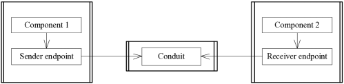
Each of the connectors in Figure 3 is implemented using three highly dependent pieces: the sender endpoint, the receiver endpoint, and the conduit(s). These are implemented as a cohesive unit to guarantee the communication takes place correctly. The sender and receiver endpoints are responsible for ensuring that the appropriate protocol is obeyed. Conduits are data channels; they sit as a bridge between endpoints, with the endpoints responsible for using the conduit correctly (e.g., ensuring synchronous access). We use the term connector objects to denote the combination of endpoint objects and conduit objects, which form the realization of a particular connector.
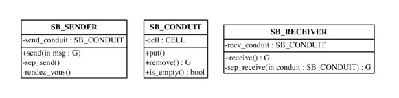
An example of a simple connector is the synchronous message buffer. It holds a single message and the sender does not proceed until the receiver has received the message. The implementation of the message buffer conduit can be seen in Figure 6.
The conduit contains a storage container with space for a single object of any type, G, and routines to set, clear, and report on the contents of the container. The core behavior of the connector is encoded in the endpoints. In Figure 7, the sender guarantees it only proceeds after the receiver has removed the message by using the wait condition conduit.is_empty in the rendez_vous routine. Likewise, the receiver waits on message arrival. The implementation details are hidden from the external interface of the end points, only the send and receive routines are exposed, making the interface, Figure 8b, quite simple. The usage of this connector can be seen in the object diagram in Figure 8a, which is the SCOOP implementation of Figure 4a.
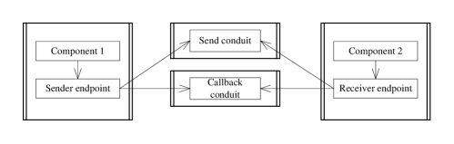
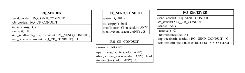
Another example is an asynchronous message queue with callback, where the sender sends its message, continues on, then waits for a reply. The queue with callback connector sends and receives messages of type G and H, respectively. This is seen in the implementation given in Figure 9a, which is the SCOOP implementation of Figure 4d.
The connector is implemented using two independent conduits; one conduit is responsible for carrying outgoing messages and the other for replies (this pattern is common in connectors with reply). The sender uses the conduits in two basic ways:
-
•
Sending a message, along with its identity. This allows the receiving end to send a message back to it.
-
•
Receiving the callback from the other end. The sender’s identity is used once again to select the correct message to receive.
Figure 10 shows the endpoint with which the sender will transmit its message and receive the callback. One wait condition indicates that there is space in the queue to send, and the other indicates that there is a callback waiting for the sender. The interface of this endpoint is simply the send and accept procedures, as seen in Figure 9b.
4.3 Integrating components and connectors
Since connectors come in three parts: sender/receiver endpoints and the conduits, any component that wants to use a connector must have access to the connector’s endpoint functionality. This can either be done by creating an endpoint object, or inheriting from the appropriate endpoint class. Because the conduits are an implementation detail of the endpoints, components do not need a direct reference to the conduits.
An example where the conduit is given as an argument to the component is given in Figure 11. The PRINTER class is responsible for accepting strings from the connector and writing them to a physical piece of paper. Upon creation the printer is given the conduit on which to receive the data, and at runtime it continually waits on the endpoint’s receive method for new data. The other end of the communication is a processor that is generating the print jobs. In this case it also initially sets up the printer, although this is not a requirement, a third party could create both COMPUTER and PRINTER. The setup can be seen in Figure 12.
4.4 Mapping to other concurrent languages
In general, the COMET design patterns should be implementable by a variety of concurrent object-oriented languages besides SCOOP. The choice of language depends on the requirements of the final system (e.g., execution guarantees).
As an example of another mapping, we consider an alternative implementation for Java. While similar, the two implementations differ in several ways. Firstly, the Java system must rely on programmer competence to ensure data race freedom; this is a manual and generally difficult task. As all data is potentially shared in Java programs, one must determine which data is read/written by more than one thread, and protect it accordingly. SCOOP does not require such manual tasks, as it ensures data race freedom by construction. In SCOOP it is impossible to access the data from both the sending and receiving side, while in Java this is possible.
Secondly, the concurrent data structures used (such as the concurrent queues used in the connectors) require different implementation styles due to the language. Although Java contains first-class support for concurrent programming through the inclusion of monitors for every object, implementing a concurrent queue still requires a measure of caution. For example, implementing a condition variable requires the identification of the condition, waiting on the object that embodies the condition, and having a corresponding signal in another routine that is fired only when the condition is true. All of these actions have the possibility to introduce an error. In SCOOP, these manual tasks (condition identification, wait, and notification) are rolled into a single concept: the wait condition. Signaling and waiting happen automatically, reducing the problem to only ensuring that the correct precondition is used.
Java and SCOOP (in its current implementation) differ in expressivity in one important case: SCOOP can successfully implement all but one of COMET’s suggested behavioral stereotypes (no “multi-read entities”); Java on the other hand has no problems with multiple readers. This is not a special characteristic of the SCOOP model: this limitation is shared by all actor and message-passing concurrency models, where shared memory is not considered. Work is in progress to remove this limitation in SCOOP by allowing multiple pure functions to access an object concurrently; purity of the function is determined by either programmer annotations or static analysis.
5 Case study
This section applies the suggested development method to an ATM system, [7], shown in Figure 13a. The full implementation of the case study, together with the design pattern implementations, can be found online at [16].
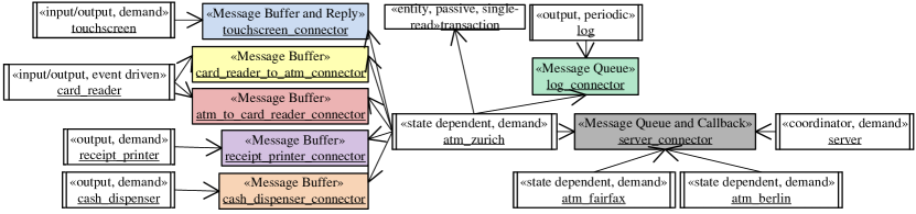
We chose the ATM system as an example, as it employs a wide spectrum of communication patterns: the synchronous patterns for an ATM’s I/O devices and the asynchronous patterns for logging and the communication with the server. In particular, the example covers all of the connectors defined by COMET.
In the ATM system, a central server manages the pins and numbers of the ATM cards, the mapping of ATM cards to bank accounts, and the bank accounts themselves. The server communicates with a number of ATMs over a message queue and callback connector. It waits for a request from an ATM and then processes the request: it either validates a pin, withdraws money, transfers money, or returns the balance of a bank account. Each ATM is state dependent and coordinates a number of simple components: its touchscreen, its card reader, its receipt printer, and its cash dispenser; a passive transaction keeps track of the customer’s data. The ATM and the card reader are connected to each other over two message buffers: one for the initial card inserted message from the card reader to the ATM and one for the return card message from the ATM to the card reader. Each ATM additionally keeps a log to record important events; the log periodically reads from a message queue and saves the events to a permanent storage.
If the ATM design should accommodate more than one server, then the server connector can simply be used to dispatch the requests to multiple severs, rather than just one. In this way, the system can achieve greater scalability due to the concurrent processing of requests.
5.1 Applying the design pattern implementations
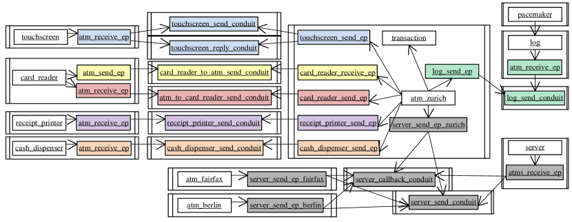
The design pattern implementations from Section 4 can be used to build a SCOOP implementation of the ATM system. Each active component in the design becomes a component object handled by a separate processor; passive components become component objects handled by one of the processors for an active component object. The class of a component object inherits from the framework class that corresponds to the component’s stereotype. For instance, the active ATM component becomes an object handled by a separate processor, and the passive transaction component becomes an object handled by the same processor as the ATM object. The ATM is a state dependent controller, and hence the class of the ATM object inherits from the corresponding framework class. Figure 13b illustrates the result of this mapping.
Each connector becomes either one or two conduit objects on separate processors, as described in Section 4. For instance, a message queue and callback connector becomes a send conduit and a reply conduit on two separate processors. Whenever two components are connected over a connector, the resulting component objects each instantiate a non-separate endpoint object whose class inherits from the corresponding endpoint class. For instance, all ATMs share a message queue and callback connector to communicate with the server. Each ATM object instantiates an endpoint object of type RQ_SENDER to implement the sending endpoint of the connector; the server instantiates an endpoint object of type RQ_RECEIVER to implement the receiving endpoint.
5.2 Implementing interconnections
The design in Figure 13a describes the interconnection of the components and connectors; however, it leaves the realization of these interconnections to the implementation. The root object is suitable to setup the objects representing control components, i.e., the server object and the ATM objects. To do so, the root object first creates the conduit objects that connect these control component objects. It then creates the control component objects and passes the conduit objects during creation; the component objects can then create local endpoint objects. After creation, the root object starts the new component objects, as shown in Figure 14. To be brief, type parameters for the connectors are omitted, and variable names are shortened.
Each object representing a controlled component can be created by the controlling object. To do so, the control object first creates the conduit objects for the connectors along with local endpoint objects. It then creates the controlled object using the conduit objects. For instance, each ATM object creates a touchscreen object, a card reader object, a receipt printer object, a cash dispenser object, and a log object on separate processors. For each of these, the ATM object uses an endpoint object with suffix ep, as shown in Figure 15.
5.3 Implementing interactions
The interactions between components can be implemented in the start features of the component objects. For instance, an ATM object executes a loop where each iteration begins with a message from the card reader object. Upon receiving this message, the ATM object retrieves the pin from the touchscreen object, validates the pin with the server object, logs the result, and then proceeds according to the customer’s choice. The ATM object stores the intermediate results into a transaction object. For this purpose, the ATM object creates the transaction object on its own processor when it receives a message, as shown in Figure 16.
The server object executes a similar loop: it waits for messages from one of the ATM objects and acts according to the message’s nature. It then reports whether or not it was able to process the request successfully.
5.4 Discussion
The case study was a manual effort; the proposed development method has however the potential for automation. Deriving an implementation from the UML design involves the following steps:
-
1.
Generate one class for each component. The class inherits from the framework class corresponding to the component’s stereotype. For each of the component’s connectors, the class has an attribute for the connector’s endpoint object; for each passive component, the class has an attribute as well. The class has a creation procedure to initialize these attributes. For each connector, the creation procedure takes the connector’s conduit objects as arguments and uses them to initialize the endpoint object. Finally, the creation procedure creates a non-separate component object for each passive component.
-
2.
Generate one root class. The root class first creates the conduit objects for each connector. It then creates a component object on a separate processor for each active component. It links the component objects according to the design by passing the conduit objects during construction. Lastly, the root class triggers the execution of all created component objects.
-
3.
In each component class, add code that implements the component’s specification. This code contains the interactions between the component objects over the connector objects.
The first and second step can be automated because the necessary information is available in the design. However, the design does not capture the application logic. Hence, a tool can only generate templates to which developers must manually add the logic in the third step.
The systematic mapping of components and connectors to objects and processors ensures traceability. Each object in the application can be mapped to exactly one component or connector; vice versa, each component and connector can be mapped to a distinct set of objects.
6 Related work
Software design patterns provide a tried and tested solution to a design problem in the form of a reusable template, which can be used in the design of new software applications. Software architectural patterns [4] address the high-level design of the software architecture [17, 20], usually in terms of components and connectors. These include widely used architectures [1] such as client/server and layered architectures. Design patterns [6] address smaller reusable designs than architectural patterns in terms of communicating objects and classes customized to solve a general design problem in a particular context. The patterns described in this paper are aimed at developing concurrent applications and are hence different from patterns for sequential applications.
Component technologies [20, 19] have been developed for distributed applications. Examples of this technology include client-side Java Beans and server-side Enterprise Java Beans (EJB). A bean is a reusable component that typically consists of multiple objects. EJBs encapsulate application logic that can be accessed by client beans. EJB containers provide system-wide services such as message communication and transaction management.
Patterns for concurrent and networked objects are described in [15]; the patterns are comprehensive and largely oriented to middleware development. However, these patterns are not used to systematically derive a concurrent program from a design, as it is the case in our approach.
Fliege et al. [5] present design patterns to detect fail-silent components in concurrent real-time systems and use them to implement an airship control system. Bellebia and Douin [2] use design patterns to develop a middleware for embedded systems. Some of their patterns also address component structures and communication between concurrent components. In contrast to our work, the design patterns in these two works focus on failure detection and middlewares, respectively, and do not capture general interactions between concurrent components. Pettit and Gomaa [14] represent UML models using colored Petri nets to conduct behavioral analyses (e.g., timing behavior). Our work focuses on obtaining an executable system with built-in behavioral guarantees; in future work, the two approaches could be combined to offer both safe execution and advanced behavioral analyses of the model.
A number of approaches address the generation of code from design patterns, e.g., [3, 13]. These approaches reduce the work needed to apply existing design patterns to a program. However, they do not generate code for designs of entire concurrent programs.
Shousha et al. [18] present an approach to detect data races in UML models of concurrent programs. Our approach prevents data races entirely because SCOOP programs are data race free by design. Hence, it is unnecessary to perform such an analysis in our approach.
7 Conclusion
With the increasing need of concurrency, offering adequate support to developers in designing and writing concurrent applications has become an important challenge. The approach taken in this paper is to base such support on widely used architectural modeling principles, namely UML with the COMET method, which should simplify adoption in industrial settings. We defined a mapping of COMET’s behavioral design patterns into SCOOP programs and demonstrated with a case study that using this approach entire concurrent UML designs can be systematically mapped to executable programs. Choosing SCOOP rather than another concurrent language has the important benefit that the resulting programs inherit SCOOP’s execution guarantees, i.e., are data-race free by construction.
For future work, it would be interesting to integrate our method with other approaches based on UML and the COMET method, giving rise to a more comprehensive framework with additional analyses of concurrent designs, e.g., concerning their timing properties [14]. In the long term, we would like to provide an automated method to translate UML concurrent software architecture designs to an implementation. We are also planning to implement further patterns, for example event-based, transaction-based, and brokered patterns, used exclusively in distributed communication.
Acknowledgments
The research leading to these results has received funding from the European Research Council under the European Union’s Seventh Framework Programme (FP7/2007-2013) / ERC Grant agreement no. 291389, the Hasler Foundation, and ETH (ETHIIRA).
References
- [1] Len Bass, Paul Clements, and Rick Kazman. Software Architecture in Practice. Addison-Wesley, 2nd edition, 2003.
- [2] D. Bellebia and J-M. Douin. Applying patterns to build a lightweight middleware for embedded systems. In Proceedings of the 6th Conference on Pattern Languages of Programs (PLoP’06), pages 1–13. ACM, 2006.
- [3] F. J. Budinsky, M. A. Finnie, J. M. Vlissides, and P. S. Yu. Automatic code generation from design patterns. IBM Systems Journal, 35(2):151–171, 1996.
- [4] Frank Buschmann, Regine Meunier, Hans Rohnert, Peter Sommerlad, and Michael Stal. Pattern-oriented software architecture: a system of patterns. John Wiley & Sons, 1996.
- [5] Ingmar Fliege, Alexander Geraldy, Reinhard Gotzhein, Thomas Kuhn, and Christian Webel. Developing safety-critical real-time systems with SDL design patterns and components. Computer Networks, 49(5):689–706, 2005.
- [6] Erich Gamma, Richard Helm, Ralph Johnson, and John Vlissides. Design patterns: elements of reusable object-oriented software. Addison-Wesley, 1995.
- [7] Hassan Gomaa. Designing Concurrent, Distributed, and Real-Time Applications with UML. Addison-Wesley, 2000.
- [8] Hassan Gomaa. Software Modeling and Design: UML, Use Cases, Patterns, and Software Architectures. Cambridge University Press, 2011.
- [9] Bertrand Meyer. Object-Oriented Software Construction. Prentice-Hall, 2nd edition, 1997.
- [10] Benjamin Morandi, Sebastian S. Bauer, and Bertrand Meyer. SCOOP – a contract-based concurrent object-oriented programming model. In Peter Müller, editor, Advanced Lectures on Software Engineering, Lecture Notes in Computer Science, pages 41–90. Springer, 2010.
- [11] Sebastian Nanz, Faraz Torshizi, Michela Pedroni, and Bertrand Meyer. Design of an empirical study for comparing the usability of concurrent programming languages. In Proceedings of the 11th International Symposium on Empirical Software Engineering and Measurement (ESEM’11), pages 325–334, 2011.
- [12] Piotr Nienaltowski. Practical framework for contract-based concurrent object-oriented programming. PhD thesis, ETH Zurich, 2007.
- [13] Mika Ohtsuki, Akifumi Makinouchi, and Norihiko Yoshida. A source code generation support system using design pattern documents based on SGML. In Proceedings of the 6th Asia-Pacific Software Engineering Conference (APSEC’99), pages 292–299. IEEE Computer Society, 1999.
- [14] Robert G. Pettit, IV and Hassan Gomaa. Modeling behavioral design patterns of concurrent objects. In Proceedings of the 28th International Conference on Software Engineering (ICSE’06), pages 202–211. ACM, 2006.
- [15] Douglas Schmidt, Michael Stal, Hans Rohnert, and Frank Buschmann. Pattern-oriented software architecture: patterns for concurrent and networked objects. John Wiley & Sons, 2000.
- [16] SCOOP implementations of design patterns. https://github.com/scottgw/scoop_design_patterns, 2012.
- [17] Mary Shaw and David Garlan. Software architecture: perspectives on an emerging discipline. Prentice-Hall, 1996.
- [18] Marwa Shousha, Lionel Briand, and Yvan Labiche. A UML/SPT model analysis methodology for concurrent systems based on genetic algorithms. In Proceedings of the 11th International Conference on Model Driven Engineering Languages and Systems (MoDELS’08), pages 475–489. Springer, 2008.
- [19] Clemens Szyperski. Component Software: Beyond Object-Oriented Programming. Addison-Wesley, 2nd edition, 2002.
- [20] R. N. Taylor, N. Medvidovic, and E. M. Dashofy. Software Architecture: Foundations, Theory, and Practice. Wiley, 2009.
- [21] Faraz Torshizi, Jonathan S. Ostroff, Richard F. Paige, and Marsha Chechik. The SCOOP concurrency model in Java-like languages. In Communicating Process Architectures, pages 155–178, 2009.
- [22] Scott West, Sebastian Nanz, and Bertrand Meyer. A modular scheme for deadlock prevention in an object-oriented programming model. In 12th International Conference on Formal Engineering Methods (ICFEM’10), volume 6447 of Lecture Notes in Computer Science, pages 597–612. Springer, 2010.