Optically guided linear Mach Zehnder atom interferometer
Abstract
We demonstrate a horizontal, linearly guided Mach Zehnder atom interferometer in an optical waveguide. Intended as a proof-of-principle experiment, the interferometer utilises a Bose-Einstein condensate in the magnetically insensitive state of Rubidium-87 as an acceleration sensitive test mass. We achieve a modest sensitivity to acceleration of m/s2. Our fringe visibility is as high as 38% in this optically guided atom interferometer. We observe a time-of-flight in the waveguide of over half a second, demonstrating the utility of our optical guide for future sensors.
Over the past decade there has been significant interest in the application of Bose-Einstein condensates (BEC) to the development of compact inertial sensors based on magnetically guided ultra-cold atoms Fortágh and Zimmermann (2007); Farkas et al. (2010). Trapped atom systems offer the possibility of the ultra-high precision sensing demonstrated by free-space atom interferometry Schmidt et al. (2011); van Zoest et al. (2010) in a more compact package. Atoms can now be Bose-condensed Schneider et al. (2003); Ott et al. (2001); Hänsel et al. (2001); Horikoshi and Nakagawa (2006a), guided Key et al. (2000); Leanhardt et al. (2002), split Denschlag et al. (1999); Cassettari et al. (2000); Hinds et al. (2001), switched Müller et al. (2001), recombined Tonyushkin and Prentiss (2010) and imaged Huet et al. (2012); Smith et al. (2011) in reconfigurable magnetic potentials which support the atoms against gravity. Typical geometries for magnetically trapped atom interferometers use either atoms bound to a trap which is adiabatically deformed Shin et al. (2004, 2005); Jo et al. (2007); Schumm et al. (2005a) or a magnetic guide in which atoms are manipulated using a standing wave Garcia et al. (2006); Wu et al. (2004); Wang et al. (2005); Wu et al. (2007); Su et al. (2010).
Precision in these schemes is usually limited by both the roughness of the magnetic waveguide potential which causes decoherence and fragmentation of the condensate Schumm et al. (2005b); Jones et al. (2003); Leanhardt et al. (2003); Fortágh et al. (2002), as well as interaction induced dephasing due to the tight trapping potentials used in magnetic guiding Chen and Egger (2003); Horikoshi and Nakagawa (2006b); Kreutzmann et al. (2004). Methods used to address these problems have included a Michelson configuration which is only sensitive to relative acceleration between the two arms Wang et al. (2005); Kafle et al. (2011), a constant displacement scheme with an inherently reduced scaling in sensitivity to absolute accereration Su et al. (2010), or trapping currents oscillating in the kHz range which smooths the potential but causes unwanted heating Trebbia et al. (2007); Bouchoule et al. (2008). The impact of these problems has been highlighted in Ref. Marti et al. (2012).
An alternative solution using optical trapping and manipulation of ultra cold atoms has the advantage of being inherently smooth. Optical elements have been constructed which guide Bongs et al. (2001); Guerin et al. (2006); Gattobigio et al. (2009); Dall et al. (2010), reflect Fabre et al. (2011); Cheiney et al. (2012) and split Houde et al. (2000); Gattobigio et al. (2012); Dumke et al. (2002) atom clouds. Recently, a ring interferometer has been constructed to measure rotation Marti et al. (2012). Additionally, relatively large BECs can be quickly produced in optical traps ( atoms in 500ms Clément et al. (2009)) and the atoms in an optical trap can be confined in any internal state, allowing the trapping of magnetically insensitive ensembles Altin et al. (2011).
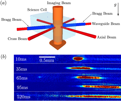
In this paper we present the first linear, optically guided atom interferometer in an inertially sensitive configuration. A BEC of 87Rb is loaded into an atomic waveguide constructed from a far-detuned optical dipole beam (Fig. 1). The atoms are then transferred into the first-order magnetically insensitive spin state. A Mach-Zehnder (MZ) atom interferometer with momentum splitting is constructed using counter-propagating Bragg beams aligned co-linear with the waveguide. The phase of a MZ atom interferometer is given by Müller et al. (2008a)
| (1) |
where is the wavevector of the light used in the th order Bragg transitions, is the acceleration experienced by the atoms from external forces, is the rate at which the angular frequency difference between the Bragg beams is swept, is the time between pulses in the interferometer of total length and is the phase of the th Bragg laser pulse. Tuning the interferometer phase to zero using provides a measure of the acceleration along . We demonstrate this by measuring the small residual component of gravity along the near-horizontal waveguide.
We produce 87Rb condensates using the machine described in Ref Altin et al. (2010). Briefly, we evaporatively cool atoms in their lower ground state in a quadrupole-Ioffe configuration magnetic trap before transferring them into an optical ‘triple trap’. The ‘triple trap’ is constructed using three red-detuned dipole beams (see Fig. 1). The cross and axial beams are sourced from a single laser (SPI RedPower compact) operating at nm, while the third beam (SPI RedPower HS) which operates at nm is also later used as our optical waveguide. The waist radii of our axial, cross and waveguide beams are measured to be m, m and m respectively. The waveguide beam is held on at a constant power of W. The crossed dipole beams are adiabatically ramped down from W to W over s which further evaporatively cools the atoms, producing a BEC of atoms. Our slow repetition rate of 0.5/min is largely dominated by the need for thermal dissipation from our magnetic trap, and it is possible to form BEC much faster than this Lin et al. (2009); Clément et al. (2009).
To release the atoms into the waveguide we ramp the crossed dipole beams down to mW over 0.5s before switching them off entirely. The remaining optical waveguide beam has transverse and axial frequencies of 114Hz (measured by exciting a trap oscillation) and 1Hz (calculated from the beam properties) respectively, and is on a tilt of less than with respect to gravity. Consequently the atoms slowly accelerate out of the field of view of our vertical imaging system ( 3mm) after around 100ms. We observed the condensate expanding along the waveguide without aberration for times on the order of 0.5s (Fig. 1) by using a Bloch acceleration Cadoret et al. (2008) up the slight incline and observing the atom cloud as it falls back down the waveguide. After the BEC is released into the waveguide, we allow it to expand axially for 20ms to reduce any mean-field effects which may be present due to inter-particle interactions at higher density Debs et al. (2011). After expansion we measure the momentum width in the directions axial and transverse to the waveguide to be and respectively. Using time of flight observations we have determined that the majority of the atoms occupy the transverse ground state of the waveguide.
While the BEC expands along the waveguide a constant magnetic field of Gauss is applied by a pair of Helmholtz coils to define the spin axis. During this time the atoms are transferred into the first-order magnetically insensitive state using a Landau-Zener radio frequency sweep. We can verify that the atoms are in the state by hitting the cloud with a short magnetic pulse, knocking them out of the waveguide if they are in the state but leaving them trapped if they are in the state.
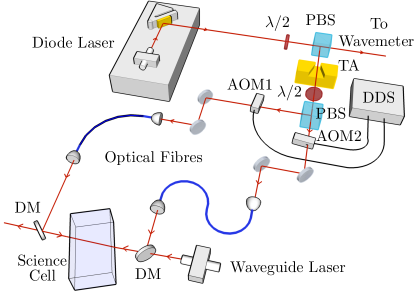
We use Bragg transitions to coherently split, reflect and recombine our atomic wavepacket in momentum along the waveguide Debs et al. (2011); Müller et al. (2008a). Our Bragg setup is shown schematically in Figure 2. For counter-propagating beams an th order Bragg pulse, imparting momentum to the kicked atoms, has a resonance condition given by , where is the wavenumber of the light and is the mass of the atoms. We use kHz to effect second order Bragg transitions. To account for the doppler shift induced by the acceleration of approximately 0.10m/s2 down the waveguide due to gravity (as measured by time-of-flight in the waveguide), one of the beams is swept by Hz/ms in the laboratory frame so as to remain resonant, with no doppler shift in the frame of the atoms. We use gaussian pulses to achieve optimal momentum state coupling efficiencies Szigeti et al. (2012); Müller et al. (2008b).
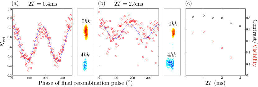
Using the Bragg setup we build a Mach-Zehnder interferometer. First a pulse is applied to coherently split the atoms into two momentum states, one initially stationary at , the other travelling at . After a time we apply a pulse to invert the two momentum states. After another period , the two halves of the atomic wave packet are overlapped again and we apply a second pulse to interfere the two states. We allow these final states to separate along the waveguide for ms, then switch off the waveguide to allow ballistic expansion for 5ms to avoid lensing of the imaging light by the narrow, dense cloud of atoms. Using absorption imaging we count the number of atoms in each momentum state. To remove the effect of run-to-run fluctuations in total atom number, we look at the relative atom number in the state . By scanning the relative phase of the final pulse, we obtain fringes in , and these are shown in Fig. 3.
A simple method to count the atoms in each state is to draw a box around the area where each state is expected and count the atoms in each box for each phase . To avoid counting non-contributing pixels in our image, which would add unnecessary noise, we use a Fourier phase decomposition algorithm to select which pixels we attribute to each momentum state. For each pixel in our absorption image we calculate the number of atoms it contains as a function of recombination phase, . We then take the inner product with sinusoids of the expected frequency
| (2) |
where is 2 for a transition. Any oscillatory signal in of the correct frequency such as can be extracted by the relations
| (3) |
For a small phase offset ( for the 0 state) it is sufficient to simply plot , as and , and this has been done in Fig. 3. Ideally, two identifiable components will be visible in an image, the momentum state with (with positive amplitude, shown in red) and the momentum state with (negative amplitude, blue). From this image we select which pixels to include in our regular counting of and for all by setting a tolerance on . The optimal tolerance will depend upon the background noise in the image.
An example of the obtained fringes are shown in Fig. 3. We obtain a visibility of at ms and at ms. By ms, phase noise effectively randomises the final phase of the interferometer, but interference is still visible. Even at ms we still have interference with contrast of , albeit with random phase. The phase instability observed at longer interferometer times is likely due to acoustic vibrations affecting the optical fibre out-couplers which bring the Bragg beams to the table. A simple analysis shows that a small fluctuation in the distance between fibre out-couplers creates a laser phase offset (in radians) of . For the sake of argument, assume , is enough to mask a usable signal, this means that nm is enough displacement during the interrogation time to completely wash out any fringes. This could be caused by a vibration with a 70nm amplitude and frequency around Hz with =4ms, for example. Indeed, by looking at the beat between our Bragg beams on a low-frequency spectrum analyser we see a significant noise peak between 130Hz and 200Hz in our laboratory.
The highest sensitivity to acceleration along the guide that we can currently obtain is m/s2 at ms over 136 runs (), and we obtain an acceleration of m/s2. For comparison, a free space gravimeter run in the same lab Debs et al. (2011) had an acceleration sensitivity of m/s2 at ms over 30 runs (). The similar results obtained for both the free space and guided interferometer indicate that it is likely that by vibrationally isolating the sensor and Bragg laser system from the mechanical noise present in our laboratory we can achieve significantly higher sensitivity. Indeed, a precision atom interferometer based gravimeter, operated in a vibrationally isolated laboratory next to the one in which the current apparatus resides achieves an acceleration sensitivity of Altin et al. (2012) for ms. The fundamental atomic projection noise limit on acceleration sensitivity for this type of system is given by where is the total number of atoms involved in several runs of the experiment Altin et al. (2011). For our longest waveguide propagation time of ms this limit is an enticing m/s2 . In this hypothetical interferometer we would have a maximum displacement between the atom clouds of 3.6mm, or 10% of the Rayleigh length in either direction and the resulting change in waveguide intensity experienced by the atoms will be less than 1%.
There are numerous avenues for future research in this system. If vibrational noise can be reduced, we can begin to explore the fundamental limitations of signal to noise in the waveguide interferometer, and additionally make a direct comparison to a free space system in the same machine. The ability to hold all magnetic substates in the same waveguide spatial mode with an arbitrary, constant magnetic field offers another interesting prospect: completely removing the self-interaction in such a system by setting the scattering length to zero Fattori et al. (2008); Gustavsson et al. (2008). In fact, our apparatus can also produce BEC of 85Rb and manipulate the s-wave scattering length via an easily accessible Feshbach resonance at 155G Altin et al. (2010). Combining the optical waveguide interferometer with a time varying scattering length could also allow investigation of squeezing enhanced interferometry Johnsson and Haine (2007); Haine and Johnsson (2009); Esteve et al. (2008). Finally, we have made preliminary investigations of an alternative to two-photon beam splitters and mirrors in the waveguide. By replacing the Bragg mirror with a blue detuned light sheet at 532nm we have constructed a hybrid interferometer, which will be the subject of an upcoming paper. The system also offers the possibility of superimposing multidimensional lattices onto the propagating atoms to create the equivalent of photonic crystals for the propagating atoms.
In summary we have demonstrated a proof-of-principle acceleration sensor based upon Bragg interferometry in an optical waveguide. Our Mach-Zender configuration atom interferometer is sensitive to acceleration along the waveguide axis. As the atoms are optically trapped we are able to operate the interferometer with atoms in the magnetically insensitive internal state. We have demonstrated clean propagation in the optical waveguide without fragmentation for more than half a second. In the future, this single axis system could be readily adapted to produce a multi-axis inertial sensor by including two additional orthogonal waveguide atom interferometers.
References
- Fortágh and Zimmermann (2007) J. Fortágh and C. Zimmermann, Rev. Mod. Phys. 79, 235 (2007).
- Farkas et al. (2010) D. M. Farkas, K. M. Hudek, E. A. Salim, S. R. Segal, M. B. Squires, and D. Z. Anderson, Applied Physics Letters 96, 093102 (pages 3) (2010).
- Schmidt et al. (2011) M. Schmidt, A. Senger, M. Hauth, C. Freier, V. Schkolnik, and A. Peters, Gyroscopy and Navigation 2, 170 (2011).
- van Zoest et al. (2010) T. van Zoest, N. Gaaloul, Y. Singh, H. Ahlers, W. Herr, S. T. Seidel, W. Ertmer, E. Rasel, M. Eckart, E. Kajari, et al., Science 328, 1540 (2010).
- Schneider et al. (2003) S. Schneider, A. Kasper, C. vom Hagen, M. Bartenstein, B. Engeser, T. Schumm, I. Bar-Joseph, R. Folman, L. Feenstra, and J. Schmiedmayer, Phys. Rev. A 67, 023612 (2003).
- Ott et al. (2001) H. Ott, J. Fortagh, G. Schlotterbeck, A. Grossmann, and C. Zimmermann, Phys. Rev. Lett. 87, 230401 (2001).
- Hänsel et al. (2001) W. Hänsel, T. Hommelhoff, T. Hänsch, and J. Reichel, Nature 413, 498 (2001).
- Horikoshi and Nakagawa (2006a) M. Horikoshi and K. Nakagawa, Applied Physics B 82, 363 (2006a).
- Key et al. (2000) M. Key, I. G. Hughes, W. Rooijakkers, B. E. Sauer, E. A. Hinds, D. J. Richardson, and P. G. Kazansky, Phys. Rev. Lett. 84, 1371 (2000).
- Leanhardt et al. (2002) A. E. Leanhardt, A. P. Chikkatur, D. Kielpinski, Y. Shin, T. L. Gustavson, W. Ketterle, and D. E. Pritchard, Phys. Rev. Lett. 89, 040401 (2002).
- Denschlag et al. (1999) J. Denschlag, D. Cassettari, A. Chenet, S. Schneider, and J. Schmiedmayer, Applied Physics B: Lasers and Optics 69, 291 (1999).
- Cassettari et al. (2000) D. Cassettari, B. Hessmo, R. Folman, T. Maier, and J. Schmiedmayer, Phys. Rev. Lett. 85, 5483 (2000).
- Hinds et al. (2001) E. A. Hinds, C. J. Vale, and M. G. Boshier, Phys. Rev. Lett. 86, 1462 (2001).
- Müller et al. (2001) D. Müller, E. A. Cornell, M. Prevedelli, P. D. D. Schwindt, Y.-J. Wang, and D. Z. Anderson, Phys. Rev. A 63, 041602 (2001).
- Tonyushkin and Prentiss (2010) A. Tonyushkin and M. Prentiss, Journal of Applied Physics 108, 094904 (pages 5) (2010).
- Huet et al. (2012) L. Huet, M. Ammar, E. Morvan, N. Sarazin, J.-P. Pocholle, J. Reichel, C. Guerlin, and S. Schwartz, Applied Physics Letters 100, 121114 (pages 3) (2012).
- Smith et al. (2011) D. A. Smith, S. Aigner, S. Hofferberth, M. Gring, M. Andersson, S. Wildermuth, P. Krüger, S. Schneider, T. Schumm, and J. Schmiedmayer, Opt. Express 19, 8471 (2011).
- Shin et al. (2004) Y. Shin, M. Saba, T. A. Pasquini, W. Ketterle, D. E. Pritchard, and A. E. Leanhardt, Phys. Rev. Lett. 92, 050405 (2004).
- Shin et al. (2005) Y. Shin, C. Sanner, G.-B. Jo, T. A. Pasquini, M. Saba, W. Ketterle, D. E. Pritchard, M. Vengalattore, and M. Prentiss, Phys. Rev. A 72, 021604 (2005).
- Jo et al. (2007) G.-B. Jo, Y. Shin, S. Will, T. A. Pasquini, M. Saba, W. Ketterle, D. E. Pritchard, M. Vengalattore, and M. Prentiss, Phys. Rev. Lett. 98, 030407 (2007).
- Schumm et al. (2005a) T. Schumm, S. Hofferberth, L. Andersson, S. Wildermuth, S. Groth, I. Bar-Joseph, J. Schmiedmayer, and P. Krüger, Nature Physics 1, 57 (2005a).
- Garcia et al. (2006) O. Garcia, B. Deissler, K. J. Hughes, J. M. Reeves, and C. A. Sackett, Phys. Rev. A 74, 031601 (2006).
- Wu et al. (2004) S. Wu, W. Rooijakkers, P. Striehl, and M. Prentiss, Phys. Rev. A 70, 013409 (2004).
- Wang et al. (2005) Y.-J. Wang, D. Z. Anderson, V. M. Bright, E. A. Cornell, Q. Diot, T. Kishimoto, M. Prentiss, R. A. Saravanan, S. R. Segal, and S. Wu, Phys. Rev. Lett. 94, 090405 (2005).
- Wu et al. (2007) S. Wu, E. Su, and M. Prentiss, Phys. Rev. Lett. 99, 173201 (2007).
- Su et al. (2010) E. J. Su, S. Wu, and M. G. Prentiss, Phys. Rev. A 81, 043631 (2010).
- Schumm et al. (2005b) T. Schumm, J. Est ve, C. Figl, J.-B. Trebbia, C. Aussibal, H. Nguyen, D. Mailly, I. Bouchoule, C. I. Westbrook, and A. Aspect, The European Physical Journal D - Atomic, Molecular, Optical and Plasma Physics 32, 171 (2005b).
- Jones et al. (2003) M. P. A. Jones, C. J. Vale, D. Sahagun, B. V. Hall, and E. A. Hinds, Phys. Rev. Lett. 91, 080401 (2003).
- Leanhardt et al. (2003) A. E. Leanhardt, Y. Shin, A. P. Chikkatur, D. Kielpinski, W. Ketterle, and D. E. Pritchard, Phys. Rev. Lett. 90, 100404 (2003).
- Fortágh et al. (2002) J. Fortágh, H. Ott, S. Kraft, A. Günther, and C. Zimmermann, Phys. Rev. A 66, 041604 (2002).
- Chen and Egger (2003) S. Chen and R. Egger, Phys. Rev. A 68, 063605 (2003).
- Horikoshi and Nakagawa (2006b) M. Horikoshi and K. Nakagawa, Phys. Rev. A 74, 031602 (2006b).
- Kreutzmann et al. (2004) H. Kreutzmann, U. V. Poulsen, M. Lewenstein, R. Dumke, W. Ertmer, G. Birkl, and A. Sanpera, Phys. Rev. Lett. 92, 163201 (2004).
- Kafle et al. (2011) R. P. Kafle, D. Z. Anderson, and A. A. Zozulya, Phys. Rev. A 84, 033639 (2011).
- Trebbia et al. (2007) J.-B. Trebbia, C. L. Garrido Alzar, R. Cornelussen, C. I. Westbrook, and I. Bouchoule, Phys. Rev. Lett. 98, 263201 (2007).
- Bouchoule et al. (2008) I. Bouchoule, J.-B. Trebbia, and C. L. Garrido Alzar, Phys. Rev. A 77, 023624 (2008).
- Marti et al. (2012) G. E. Marti, R. Olf, and D. M. Stamper-Kurn (2012), eprint arXiv:1210.0033.
- Bongs et al. (2001) K. Bongs, S. Burger, S. Dettmer, D. Hellweg, J. Arlt, W. Ertmer, and K. Sengstock, Phys. Rev. A 63, 031602 (2001).
- Guerin et al. (2006) W. Guerin, J.-F. Riou, J. P. Gaebler, V. Josse, P. Bouyer, and A. Aspect, Phys. Rev. Lett. 97, 200402 (2006).
- Gattobigio et al. (2009) G. L. Gattobigio, A. Couvert, M. Jeppesen, R. Mathevet, and D. Guéry-Odelin, Phys. Rev. A 80, 041605 (2009).
- Dall et al. (2010) R. G. Dall, S. S. Hodgman, M. T. Johnsson, K. G. H. Baldwin, and A. G. Truscott, Phys. Rev. A 81, 011602 (2010).
- Fabre et al. (2011) C. M. Fabre, P. Cheiney, G. L. Gattobigio, F. Vermersch, S. Faure, R. Mathevet, T. Lahaye, and D. Guéry-Odelin, Phys. Rev. Lett. 107, 230401 (2011).
- Cheiney et al. (2012) P. Cheiney, C. Fabre, F. Vermersch, G. G.L., R. Mathevet, T. Lahaye, and D. Guéry-Odelin (2012), eprint arXiv:1206.3687v1.
- Houde et al. (2000) O. Houde, D. Kadio, and L. Pruvost, Phys. Rev. Lett. 85, 5543 (2000).
- Gattobigio et al. (2012) G. L. Gattobigio, A. Couvert, G. Reinaudi, B. Georgeot, and D. Guéry-Odelin, Phys. Rev. Lett. 109, 030403 (2012).
- Dumke et al. (2002) R. Dumke, T. Müther, M. Volk, W. Ertmer, and G. Birkl, Phys. Rev. Lett. 89, 220402 (2002).
- Clément et al. (2009) J.-F. Clément, J.-P. Brantut, M. Robert-de Saint-Vincent, R. A. Nyman, A. Aspect, T. Bourdel, and P. Bouyer, Phys. Rev. A 79, 061406 (2009).
- Altin et al. (2011) P. A. Altin, G. McDonald, D. Döring, J. E. Debs, T. H. Barter, J. D. Close, N. P. Robins, S. A. Haine, T. M. Hanna, and R. P. Anderson, New Journal of Physics 13, 065020 (2011).
- Müller et al. (2008a) H. Müller, S.-w. Chiow, Q. Long, S. Herrmann, and S. Chu, Phys. Rev. Lett. 100, 180405 (2008a).
- Altin et al. (2010) P. A. Altin, N. P. Robins, D. Döring, J. E. Debs, R. Poldy, C. Figl, and J. D. Close, Review of Scientific Instruments 81, 063103 (2010).
- Lin et al. (2009) Y.-J. Lin, A. R. Perry, R. L. Compton, I. B. Spielman, and J. V. Porto, Phys. Rev. A 79, 063631 (2009).
- Cadoret et al. (2008) M. Cadoret, E. de Mirandes, P. Cladé, S. Guellati-Khélifa, C. Schwob, F. m. c. Nez, L. Julien, and F. m. c. Biraben, Phys. Rev. Lett. 101, 230801 (2008).
- Debs et al. (2011) J. E. Debs, P. A. Altin, T. H. Barter, D. Döring, G. R. Dennis, G. McDonald, R. P. Anderson, J. D. Close, and N. P. Robins, Phys. Rev. A 84, 033610 (2011).
- Szigeti et al. (2012) S. S. Szigeti, J. E. Debs, J. J. Hope, N. P. Robins, and J. D. Close, New Journal of Physics 14, 023009 (2012).
- Müller et al. (2008b) H. Müller, S.-w. Chiow, and S. Chu, Phys. Rev. A 77, 023609 (2008b).
- Altin et al. (2012) P. A. Altin, M. T. Johnsson, V. Negnevitsky, G. R. Dennis, R. P. Anderson, J. E. Debs, S. S. Szigeti, K. S. Hardman, S. Bennetts, G. D. McDonald, et al. (2012), eprint arXiv:1207.1595.
- Fattori et al. (2008) M. Fattori, C. D’Errico, G. Roati, M. Zaccanti, M. Jona-Lasinio, M. Modugno, M. Inguscio, and G. Modugno, Phys. Rev. Lett. 100, 080405 (2008).
- Gustavsson et al. (2008) M. Gustavsson, E. Haller, M. J. Mark, J. G. Danzl, G. Rojas-Kopeinig, and H.-C. Nägerl, Phys. Rev. Lett. 100, 080404 (2008).
- Johnsson and Haine (2007) M. T. Johnsson and S. A. Haine, Phys. Rev. Lett. 99, 010401 (2007).
- Haine and Johnsson (2009) S. A. Haine and M. T. Johnsson, Phys. Rev. A 80, 023611 (2009).
- Esteve et al. (2008) J. Esteve, C. Gross, A. Weller, S. Giovanazzi, and M. K. Oberthaler, Nature 455, 1216 (2008).