Manipulation of organic polyradicals in a single-molecule transistor
Abstract
Inspired by cotunneling spectroscopy of spin-states in a single OPE5-based molecule, we investigate the prospects for electric control of magnetism in purely organic molecules contacted in a three-terminal geometry. Using the gate electrode, the molecule is reversibly switched between three different redox states, with magnetic spectra revealing both ferromagnetic and antiferromagnetic exchange couplings on the molecule. These observations are shown to be captured by an effective low-energy Heisenberg model, which we substantiate microscopically by a simple valence bond description of the molecule. These preliminary findings suggest an interesting route towards functionalized all-organic molecular magnetism.
pacs:
85.65.+h 75.76.+j 85.35.GvI Introduction
Single molecules are of interest as active electronic components because of the small size, the possibility of self-assembly, and because of their chemical versatility. As a consequence, the study of single-molecule transport Joachim et al. (2000); Nitzan and Ratner (2003) is attracting massive interest. Gated three-terminal setups (single-molecule transistors) Park et al. (2000, 2002); Kubatkin et al. (2003) are particularly useful, since such a geometry allows detailed spectroscopy and control of the molecular device Osorio et al. (2007). Especially interesting is the prospect of exploiting the spin degree of freedom in magnetic molecules, either to interact with and control the charge- or spin currents through the system (single-molecule spintronics) Bogani and Wernsdorfer (2008); Ruben et al. (2008); Osorio et al. (2010); Zyazin et al. (2010); Sanvito (2011), or to store and manipulate quantum information (single-molecule spin qubits) Lehmann et al. (2007). In both cases, electric control of the spin states is highly desirable since, contrary to magnetic fields, these can be applied locally and varied relatively fast. Arrays of magnetic atoms, studied with spin-polarized STM, were found to be antiferromagnetically coupled Loth et al. (2012), but ferromagnetic coupling is often more desirable since a larger net magnetic moment allows easier manipulation and readout Chappert et al. (2007).
Here, we discuss the prospect for electrical manipulation of spin states within a purely organic molecule, where the radicals of the charged molecule can be coupled antiferromagnetically or ferromagnetically depending on the relative location of the added charges. This is inspired by low-temperature transport measurements on a single Coulomb blockaded device, based on a molecular ”cruciform”: thiol end-capped penta phenylene ethynylene (OPE5) with a vertically disposed redox-active tetrathiafulvalene (TTF) unit Jennum et al. (2011), see Fig. 1(a).
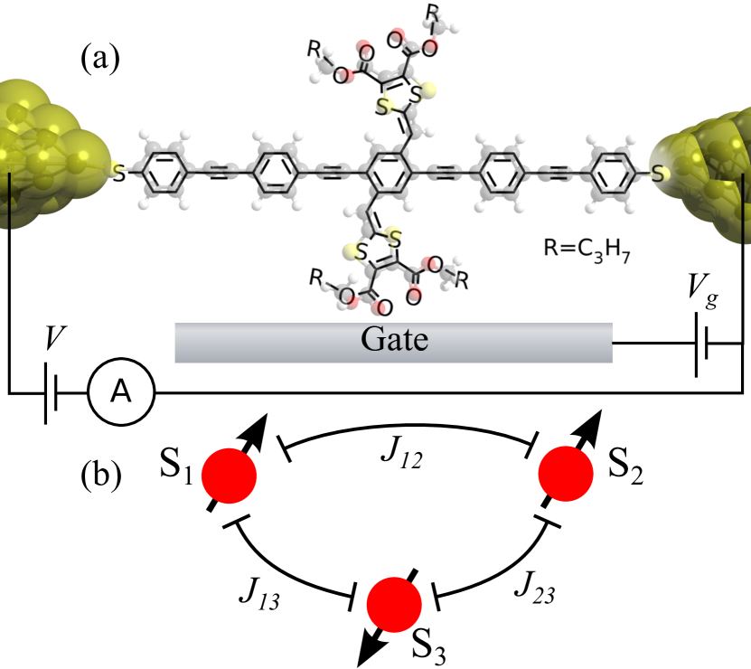
As we show below, the three-terminal transport data reveal two ferromagnetically coupled spins, and , see Fig. 1(b). Adjusting the gate voltage to remove an electron from the molecule introduces an additional spin, , which modifies the effective interaction of and by coupling to them antiferromagnetically. This system is analogous to the theoretical suggestion in Refs. Lehmann et al., 2007, 2009, where and were used as spin qubits and two-qubit operations could be performed using the gate to control their interaction by adding/removing a third spin, . Whereas the original proposal of Refs. Lehmann et al., 2007, 2009 involved an intrinsically magnetic polyoxometalate molecule, we argue here that this can be achieved also in an all-organic molecule where a ferromagnetic ground state can be induced by gate-controlled oxidation. Thus, the gated junction allows reversible switching of the molecule between different polyradical states.
II Methods
The device is made by electromigration Park et al. (1999) of a thin gold wire in a solution of the molecules, using a feedback mechanism combined with self-breaking to avoid spurious gold particle formation in the junction Strachan et al. (2005); O’Neill et al. (2007); Osorio et al. (2008). The current, , was measured as a function of source drain voltage, , and gate voltage, , at a temperature K. The differential conductance, , was obtained from pointwise linear fits of the data.
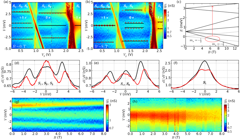
Due to intentionally low junction fabrication yields to avoid formation of junctions comprising several molecules contacted in parallel, we only obtained a single device with sufficient gate coupling () and sharp enough resonances to allow detailed spectroscopy. In the two-dimensional conductance map presented in Fig. 2(a) and (b), gate-dependent resonances indicate when is large enough to energetically allow electrons to be added to or removed from the molecule by sequential tunneling Osorio et al. (2008).
Below these lines, within the so-called Coulomb diamonds, single-electron transport is suppressed and a fixed charge is stabilized by Coulomb blockade. The two crossing points at represent charge degeneracies, and by increasing going from left to right in Fig. 2(a) and (b) a total of two electrons are added to the molecule. Inside the Coulomb diamonds transport takes place through coherent many-electron cotunneling processes DeFranceschi et al. (2001), giving rise to horizontal conductance features, which can be used to extract information about the molecular spin excitations Osorio et al. (2010); Zyazin et al. (2010). In addition, the Kondo effect Goldhaber-Gordon et al. (1998); Cronenwett et al. (1998); Nygård et al. (2000) gives rise to conductance peaks centered at .
III Results and discussion
Figure 2(a) represents a measurement in zero magnetic field, while Fig. 2(b) was taken at T. The dashed horizontal lines indicate the excitation energies in each charge state. As seen from the line scans in Figs. 2(d)–(e), the excitations at finite bias-voltage appear as a splitting of a much broader Kondo-resonance, rather than proper inelastic cotunneling steps. Therefore, we choose to read off the excitation energies from the center of the peaks rather than from their inflection points Weichselbaum et al. (2009); Schmitt and Anders (2011). For the present analysis, we shall merely extract the thresholds/splittings as an estimate of the exchange couplings and .
III.1 Spin model
From the clear observation of a Zeeman effect (Fig. 2(d)-(h)) we infer that the observed low-energy excitations must be of magnetic origin. Since changing across a charge degeneracy point adds one electron at the time and we observe no spin blockade Weinmann et al. (1995), the most general effective three-spin model is the one sketched in Fig. 1(b), described by the Hamiltonian
| (1) |
expressed in terms of three distinct states, magnetic field, , the Bohr magneton, , and the electron -factor. As we will show below, in the rightmost diamond , and in the middle one .
The model allows an accurate fit of the experimentally observed excitation energies and their magnetic field dependence (compare black full lines and red dashed lines in Fig 2(a) and (b)). Importantly, the model also correctly predicts which excitations are suppressed due to spin-selection rules (see below). The exchange couplings and electron -factor are fitted to the excitations energies in Figs. 2(a) and (b); the best fit is shown by the full black lines. We find meV, meV and . We ascribe the reduction of the -factor to a combination of the (Knight-)shift of the spin-resonance frequency due to a strong Kondo effect Weichselbaum et al. (2009) and the aforementioned uncertainty in determining the exact excitation energies Schmitt and Anders (2011). The fit is not very sensitive to the exact ratio of the relatively small couplings and , only to their sum.
In the rightmost Coulomb diamond the strong zero-bias Kondo peak and its splitting into peaks at Goldhaber-Gordon et al. (1998); Cronenwett et al. (1998); Nygård et al. (2000) in magnetic field, indicates a spin-1/2 ground state (). The molecular charge must therefore be odd, but the absolute charge state cannot be uniquely determined from the measurements. We argue below that the molecule here is singly reduced, but this is not relevant for the present discussion about the spin states.
Going to the middle diamond, one electron has been removed. The presence of a zero-bias Kondo peak still implies a spin-degenerate ground state, and removing an electron must therefore introduce an additional spin, , which couples ferromagnetically with to form a triplet ground state, resulting in a spin-1 Kondo effect Roch et al. (2009); Parks et al. (2010). That the spin has not changed by more than is consistent with the absense of spin blockade Weinmann et al. (1995). Note that, instead of the usual enhancement of the Kondo peak upon approaching the charge degeneracy point a slight depression is observed near in Fig. 2 (a). Similar observations have been made in Ref. Yu et al., 2005, but an explanation of this requires a more detailed understanding of the charge fluctuations in this specific molecule. In a magnetic field, the spin-1 Kondo peak splits into low lying peaks at . Excitations to the component of the triplet are suppressed by spin-selection rules and are therefore not present in the experiment. The strong inelastic cotunneling lines observed at higher bias-voltages indicate transitions to the excited singlet configuration and occur at .
In the leftmost diamond, yet another electron has been removed, and the molecule has acquired one more spin, (). An antiferromagnetic coupling to leads to a doublet ground state () and a quadruplet excited state () as seen in the spectrum and magnetic field dependence shown in Fig. 2(c). This explains the merging of the peaks at T as apparent from Fig. 2(d); the lowest component of the quadruplet is almost degenerate with the lowest component of the doublet, and a new effective doublet comprising these two states becomes the groundstate. As a result a stronger zero-bias Kondo effect is obtained (compare red and black lines at zero bias in Fig. 2(d)), meaning that this finite-field doublet is better coupled to the leads than the zero-field doublet. A more detailed analysis shows that this can indeed be possible, if electrons tunnel via both and . Similar behavior where a Kondo peak is split by interaction with another spin, but can be restored with a magnetic field, has been observed in STM studies of coupled magnetic and non-magnetic atoms on surfaces Otte et al. (2009). Unfortunately the device broke down, and as a consequence we do not have the full B-field dependence in this charge state, but only the conductance map at 0 and 8 T. The full B-field dependence was however acquired at the two other charge states (Fig. 2(g-h)).
The zero-bias Kondo effect arising from the ground state doublet at (Fig. 2(d), black line) is markedly weaker than that observed for the single-spin in the far right diamond (Fig. 2(f)). This can be understood by inspection of the effective three-spin ground state doublet, expressed in terms of individual spin states as:
| (2) | ||||
| (3) |
assuming for simplicity that the two antiferromagnetic couplings are equal, i.e. . The amplitudes for flipping of this doublet by a simple exchange-cotunnelling process at either or are therefore reduced by Clebsch-Gordan coefficients to respectively
| (4) |
The effective Kondo temperature depends exponentially on these amplitudes and is therefore significantly smaller than for a single spin. Since the measurement was carried out at , a reduced Kondo temperature can easily result in a smaller zero-bias conductance. Notice that the triplet correlations between and makes the effective exchange-cotunneling via effectively ferromagnetic, thus prohibiting Kondo effect altogether. This suggests that the strongest tunnel coupling to the molecule takes place via or .
III.2 Microscopic model
Having rationalized the salient features of the data in terms of the Hamiltonian in eq. III.1, we now proceed to give a likely microscopic understanding of this simple 3-spin model within a valence bond (VB) picture of the molecule Shaik and Hiberty (2008). This gives a description of the low-energy excitations of the molecule. The diagram in Fig. 1(a) shows one of the possible VB’s in the ground state of the neutral molecule. This configuration, however is not the ground state of the molecule between electrodes. We shall use it rather as a neutral, spin singlet, reference state. If we first add an electron we arrive at the state of the molecule in the rightmost diamond of the stability diagram. Adding the electron the following will happen: a bond is broken, leaving a (negatively) charged carbon atom with no spin, and a neutral carbon with an unpaired spin. These two entities (charge and spin) can now move through the molecule. The charge will be particularly stable at the electrode ends of the molecule due to the attraction by image charges Kubatkin et al. (2003); Kaasbjerg and Flensberg (2008). Spin and charge will not become totally independent, since both disrupt the local VB configurations, and staying close minimizes the disruption.
Going to the middle diamond, an electron will be removed from one of the two TTF-branches of the molecule, and the associated unpaired spin will predominantly move about in the same branch. Note that the overall molecule is neutral, but we propose that the lowest energy configuration has a negative charge close to one of the electrodes and a positive charge on one of the sulphur atoms in the TTFs. Once in a while the two spins can perform an exchange process, and this will result in either an antiferromagnetic or a ferromagnetic coupling, depending on which two branches of the molecule the two spins belong to.
The general rule, which determines the character of the magnetic coupling is related to the actual location of the involved spins. The carbon atoms in the molecule can be divided into two “sublattices”, with nearest neighbor atoms belonging to different sublattices. It is a simple fact of the VB picture, that to a very good approximation, a spin belonging to a given sublattice will stay on that sublattice. The rule now is that two spins living in the same sublattice will be ferromagnetically coupled, while two spins living on different sublattices are antiferromagnetically coupled.
For the molecule we study, the ground state of the neutral molecule (the central diamond in the stability diagram) is a spin triplet. We thus require that the two spins live on the same sublattice, which leaves only two possibilities in the choice of branches with spin and charge.
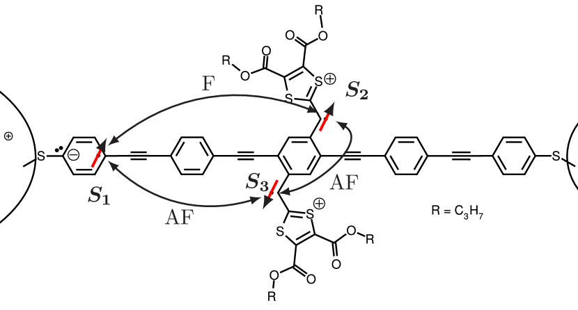
Turning to the discussion of the third diamond, we extract one more electron. The charge and the spin will inhabit a third branch of the molecule. If the first two spins were ferromagnetically coupled, the third will necessarily be antiferromagnetically coupled to the first two spins, in accordance with the simplified model used in the data analysis. Fig. 3 shows the VB of this state.
What has been described in words in the previous two paragraphs can be put into rigorous mathematics in a model, where the VB system can be mapped onto an effective Heisenberg model, with as many sites, as there are coupled orbitals in the molecule Hedegård .
IV Conclusion
In conclusion, cotunneling spectroscopy has been used to demonstrate the realization of a series of different spin states upon successive reduction of a single organic molecule. If , the Hamiltonian (III.1) is equivalent to the spin-part of Eq. (1) in Ref. Lehmann et al., 2007, and thus describes a two-spin qubit system ( and ), with an interaction which is controllable by the reversible addition / removal of . However, as long as and , adding , and removing it again after a certain time has elapsed, results in a non-trivial change of the two-qubit state spanned by and . Thus, this operation acts as a two-qubit gate.
Using a valence bond description of the molecule we have provided a microscopic motivation for the effective spin model, which, however, relies on interactions with image charges in the electrodes stabilizing a different charge-configuration than in the molecule in vacuum. Therefore, it cannot be expected that all cruciform molecule devices will behave in the same way as the single device investigated here. However, as the data stands, lacking the full B dependence in the left-most charge state, it demonstrates that the device allowed electrical control of quantum spins in an organic molecule, with the non-trivial spin states being induced by the gate-voltage, rather than being an intrinsic property of the neutral molecule. It is an important venue for future research to find new molecular structures where such controlled redox reactions give rise to the desired spin-structure in a more reproducible way. This could for example be achieved by adding more intrinsic molecular redox centers, which can stabilize multiple localized charges and spins without the need for interactions with the electrodes.
Acknowledgments
The research leading to these results has received funding from the European Union Seventh Framework Programme (FP7/2007-2013) under agreement no 270369 (“ELFOS”) and from FOM.
References
- Joachim et al. (2000) C. Joachim, J. K. Gimzewski, and A. Aviram, Nature 408, 541 (2000).
- Nitzan and Ratner (2003) A. Nitzan and M. A. Ratner, Science 300, 1384 (2003).
- Park et al. (2000) H. Park, J. Park, A. K. L. Lim, E. H. Anderson, A. P. Alivisatos, and P. L. McEuen, Nature 407, 57 (2000).
- Park et al. (2002) J. Park, A. N. Pasupathy, J. I. Goldsmith, C. Chang, Y. Yaish, J. R. Petta, M. Rinkoski, J. P. Sethna, H. D. Abruña, P. L. McEuen, et al., Nature 417, 722 (2002).
- Kubatkin et al. (2003) S. Kubatkin, A. Danilov, M. Hjort, J. Cornil, J. Brédas, N. Stuhr-Hansen, P. Hedegård, and T. Bjørnholm, Nature 425, 698 (2003).
- Osorio et al. (2007) E. A. Osorio, K. O’Neill, M. R. Wegewijs, N. Stuhr-Hansen, J. Paaske, T. Bjørnholm, and H. S. J. van der Zant, Nano Lett. 7, 3336 (2007).
- Bogani and Wernsdorfer (2008) L. Bogani and W. Wernsdorfer, Nature Materials 7, 179 (2008).
- Ruben et al. (2008) M. Ruben, A. Landa, E. Lörtscher, H. Riel, M. Mayor, H. Görls, H. B. Weber, A. Arnold, and F. Evers, Small 4, 2229 (2008).
- Osorio et al. (2010) E. A. Osorio, K. Moth-Poulsen, H. S. J. van der Zant, J. Paaske, P. Hedegård, K. Flensberg, J. Bendix, and T. Bjørnholm, Nano Lett. 10, 105 (2010).
- Zyazin et al. (2010) A. S. Zyazin, J. W. G. van den Berg, E. A. Osorio, H. S. J. van der Zant, N. P. Konstantinidis, M. Leijnse, M. Wegewijs, F. May, W. Hofstetter, C. Danieli, et al., Nano Lett. 10, 3307 (2010).
- Sanvito (2011) S. Sanvito, Chem. Soc. Rev. 40, 3336 (2011).
- Lehmann et al. (2007) J. Lehmann, A. Gaita-Ariño, E. Coronado, and D. Loss, Nature Nanotech. 2, 312 (2007).
- Loth et al. (2012) S. Loth, S. Baumann, C. P. Lutz, D. M. Eigler, and A. J. Heinrich, Science 335, 196 (2012).
- Chappert et al. (2007) C. Chappert, A. Fert, and F. N. V. Dau, Nature Mater. 6, 813 (2007).
- Jennum et al. (2011) K. Jennum, M. Vestergaard, A. Holmen Pedersen, J. Fock, J. Jensen, M. Santella, J. J. Led, K. Kilså, T. Bjørnholm, and M. B. Nielsen, Synthesis 4, 539 (2011).
- Lehmann et al. (2009) J. Lehmann, A. Gaita-Ariño, E. Coronado, and D. Loss, J. Mat. Chem. 19, 1672 (2009).
- Park et al. (1999) H. Park, A. K. L. Lim, A. P. Alivisatos, J. Park, and P. L. McEuen, Appl. Phys. Lett. 75, 301 (1999).
- Strachan et al. (2005) D. R. Strachan, D. E. Smith, D. E. Johnston, T.-H. Park, M. J. Therien, D. A. Bonnell, and A. T. Johnson, Appl. Phys. Lett. 86, 043109 (2005).
- O’Neill et al. (2007) K. O’Neill, E. A. Osorio, and H. S. J. van der Zant, Appl. Phys. Lett. 90, 133109 (2007).
- Osorio et al. (2008) E. A. Osorio, T. Bjørnholm, J.-M. Lehn, M. Ruben, and H. S. J. van der Zant, Jour. Phys. Cond. Mat. 20, 374121 (2008).
- DeFranceschi et al. (2001) S. DeFranceschi, S. Sasaki, J. M. Elzerman, W. G. van der Wiel, S. Tarucha, and L. P. Kouwenhoven, Phys. Rev. Lett. 86, 878 (2001).
- Goldhaber-Gordon et al. (1998) D. Goldhaber-Gordon, H. Shtrikman, D. Mahalu, D. Abusch-Magder, U. Meirav, and M. A. Kastner, Nature 391, 156 (1998).
- Cronenwett et al. (1998) S. M. Cronenwett, T. H. Oosterkamp, and L. P. Kouwenhoven, Science 281, 540 (1998).
- Nygård et al. (2000) J. Nygård, D. H. Cobden, and P. E. Lindelof, Nature 408, 342 (2000).
- Weichselbaum et al. (2009) A. Weichselbaum, F. Verstraete, U. Schollwock, J. I. Cirac, and J. von Delft, Phys. Rev. B 80, 165117 (2009).
- Schmitt and Anders (2011) S. Schmitt and F. B. Anders, Phys. Rev. Lett. 107, 056801 (2011).
- Weinmann et al. (1995) D. Weinmann, W. Häusler, and B. Kramer, Phys. Rev. Lett. 74, 984 (1995).
- Roch et al. (2009) N. Roch, S. Florens, T. A. Costi, W. Wernsdorfer, and F. Balestro, Phys. Rev. Lett. 103, 197202 (2009).
- Parks et al. (2010) J. J. Parks, A. R. Champagne, T. A. Costi, W. W. Shum, A. N. Pasupathy, E. Neuscamman, S. Flores-Torres, P. S. Cornaglia, A. A. Aligia, C. A. Balseiro, et al., Science 328, 1370 (2010).
- Yu et al. (2005) L. H. Yu, Z. K. Keane, J. W. Ciszek, L. Cheng, J. M. Tour, T. Baruah, M. R. Pederson, and D. Natelson, Phys. Rev. Lett. 95, 256803 (2005).
- Otte et al. (2009) A. F. Otte, M. Ternes, S. Loth, C. P. Lutz, C. F. Hirjibehedin, and A. J. Heinrich, Phys. Rev. Lett. 103, 107203 (2009).
- Shaik and Hiberty (2008) S. Shaik and P. H. Hiberty, A chemist’s guide to valence bond theory (Wiley, New Jersey, 2008).
- Kaasbjerg and Flensberg (2008) K. Kaasbjerg and K. Flensberg, Nano Lett. 8, 3809 (2008).
- (34) P. Hedegård, to be published.