Confined active nematic flow in cylindrical capillaries
Abstract
We use numerical modelling to study the flow patterns of an active nematic confined in a cylindrical capillary, considering both planar and homeotropic boundary conditions. We find that active flow emerges not only along the capillary axis but also within the plane of the capillary, where radial vortices are formed. If topological defects are imposed by the boundary conditions, they act as local pumps driving the flow. At higher activity we demonstate escape of the active defects and flow into the third dimension, indicating the importance of dimensionality in active materials. We argue that measuring the magnitude of the active flow as a function of the capillary radius allows determination of a value for the activity coefficient.
pacs:
83.50.-v,47.50.-d,87.10.-eThere is currently widespread interest in understanding active systems which are key to the physics of life processes sanchez11 ; koch11 ; sokolov07 ; riedel05 . Active systems are materials that produce their own energy, or respond to a continuous input of energy, so that they naturally operate out of thermodynamic equilibrium ramaswamy10 . Examples range from bacterial suspensions zhang10 , solutions of bio-filaments driven by molecular motors koenderink09 , active colloids dreyfus05 ; leoni08 , and cellular pattern formation nedelec97 , to flocking birds and fish cavagna09 ; katz11 and vibrated granular matter kruelle09 . Despite the diversity of these systems there is recurring behaviour, such as pattern formation dombrowski04 ; giomi11 , the prevalence of instabilities ramaswamy02 and the appearance of topological defects vicsek95 ; toner95 . An important question in formulating theories of active matter is to identify the extent to which these behaviours are generic and to then identify the dominant control parameters.
Approaches that have proved very useful in categorising passive soft matter systems are continuum theories which rely primarily on the symmetries of the problems simha02 ; kruse04 ; hatwalne04 ; luca12 . Several continuum theories have been proposed for active systems but matching theories to experiment, and giving a microscopic interpretation of the parameters, is still in its infancy koch11 . Noting that nematic ordering and topological defects have been observed in active systems sokolov07 ; wensink12 ; dogic12 , one of the most interesting candidates for a continuum approach is closely related to the Beris-Edwards equations of liquid crystal hydrodynamics simha02 ; hatwalne04 . The important addition, representing the activity, is a term in the stress proportional to the nematic tensor order parameter. Hence any gradient in the order parameter field initiates a flow.
In the bulk, the activity drives instabilities which destroy the nematic order mendelson99 ; simha02 ; saintillan07 ; wolgemuth08 . However, confining surfaces can stabilise a nematic state and corresponding time-independent flow fields. This has been demonstrated in a flat cell geometry voituriez05 ; marenduzzo07 , in cells with static and moving boundaries fielding11 . Other works have considered defect driven hydrodynamics in active circular regions surrounded by a passive background elgeti11 and spontaneous circulation in cytoplasmic streming woodhouse12 .
In this Letter we consider confined active nematic flows in a cylindrical capillary, as a common example of an experimetnally relevant geometry. This is a very rich system as topological defects can emerge naturally, as a consequence of the boundary conditions. Solving the continuum equations of motion in the flow aligning extensile regime we find that active flow emerges not only along the capillary axis but also within the plane of the capillary, where radial vortices are formed. Interplay between the primary and secondary velocities leads to a spiralling flow field with a well-defined pitch moving down the capillary. We show that topological defects, imposed by heterogeneous boundary conditions, act as sources driving the flow. We also argue that measuring the magnitude of the active flow as a function of the capillary radius allows determination of a value for the activity coefficient.
Active nematic flow is approached by using numerical modelling based on continuum equations for apolar active materials hatwalne04 ; marenduzzo07 . The model characterises the orientational order of active fluids by a symmetric and traceless order parameter tensor , with the largest eigenpair representing the magnitude and direction of the local orientational order. In parallel, the flow of the active fluid is described by a velocity flow field and density . The dynamic equations for and constitute the two governing equations of motion for the active nematic:
| (1) | |||||
| (2) | |||||
where is a derivative in time , is a derivative in the Cartesian spatial coordinate , is a rotational diffusion coefficient, is the viscosity, and is a first active parameter which can be considered just as a renormalisation of the free energy. Summation over repeated indices is assumed. The leading contribution to the active dynamics is controlled by the parameter in the active contribution to the non-Newtonian terms of the stress tensor
| (3) | |||||
| (4) |
where determines whether the active material is flow tumbling or flow aligning. The relaxation to equilibrium of is determined by the molecular field , which originates from the equilibrium free energy of an elastic anisotropic fluid, , where:
is the elastic constant, and are material constants. Finally, the generalized advection term and effective compressibility term are defined as:
| (6) | |||
| (7) |
where , and is a constant related to the hydrostatic pressure. For more details about the (non-active) model refer to beris .
We solve the dynamic equations for the active flow and the orientation order by using a hybrid Lattice Boltzmann (LB) algorithm. The time-evolution of is obtained using an explicit finite difference scheme in time, whereas the equation for is solved by a D3Q15 lattice Boltzmann method denniston04 . The simulations are performed in a circular simulation slice through a circular capillary tube with a cubic lattice; typically 4 x 200 x 200 mesh points. Along the capillary axis (), we assume periodic boundary conditions for both and , whereas at the capillary walls we take no-slip boundary conditions for (standard bounce-back) and fixed (in-plane or homeotropic) boundary conditions for . All calculations are performed at small Reynolds numbers (typically ). The results are presented in units of the nematic correlation length , the typical length scale over which the nematic order can vary, which allows for application of the results to different active systems. Typically, the correlation length a few times the length of the elementary constituents of the nematic and controls the characteristic size of the topological defects. For example, in bacterial suspensions wolgemuth08 , . Unless otherwise stated, the following values for the material parameters are used: , flow aligining regime , , , , , mesh resolution , time step ), and capillary radius . These parameters and simulation regime would be appropriate for dense bacterial suspensions wolgemuth08 , studied in microfluidic channels.
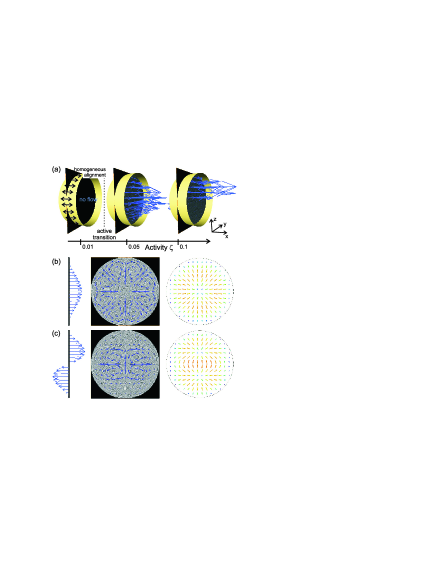
Figure 1 shows the active flow profile in a capillary with surfaces imposing homogeneous alignment, parallel to the capillary axis . Upon increasing the activity (Fig. 1a), we observe a transition to spontaneous flow. Above the transition (first panel of Fig. 1b), the leading flow is along the axis of the capillary, ( or ), depending on the random noise in the inital condition for the director (). Interestingly, at higher activities (Fig. 1c), the flow evolves into a bidirectional pattern, with the velocity in opposite halves of the capillary in opposite directions. The unidirectional flow can be interpreted as a first excited active mode and the bidirectional flow as a second excited mode, selected by stronger active forcing. In is interesting to note that the stability of the two regimes partially overlap and they can be observed at the same activity . This indicates the existence of energy barriers between active flow states. Indeed, analogous flow patterns and metastability of flow regimes was also observed in simulations of two-dimensional active nematics orlandini08 .
However the full three dimensional simulations also allow us to identify an inplane, secondary flow field within the capillary cross-section (Fig. 1b and c, second panels). The secondary flow consists of a circularly symmetric pattern of distinct vortices, 8 or 12 for the unidirectional and bidirectional flows, respectively. The vortices are pair-wise counter-rotating, thus exhibiting no net angular momentum. The magnitude of the secondary flow is of that of the primary flow. The complex structure of the flow is reflected in the active nematic director, shown in Fig. 1b and c, third panels. The director exhibits a variable splay deformation in the radial direction of the capillary and breaks the cylindrical symmetry in the bidirectional flow. Interestingly, the observed primary and secondary active flows are separately analogous to the flow phases predicted in active polar films voituriez06 .
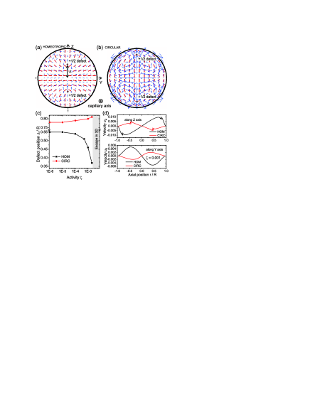
Topological defects in the orientational profiles of active materials could be used as sources of the microscopic activity, and a cylindrical capillary can naturally support such active defect profiles. Two active defect configurations are shown in capillaries with surfaces imposing homeotropic (Fig. 2a) or circular (Fig. 2b) director alignment. In both configurations, the two defect regions appear as a result of the orientational order being frustrated by the confining surfaces and are actually defect lines along the capillary with winding number. Surrounding the defects, a strictly in plane () active flow develops with zero flow component along the capillary axis. The magnitude of the flow is largest in the region surrounding the defects, which indicates that the defects act as effective local ’pumps’ for the flow. It is the strong elastic distortion and variation in the degree of order in the defect cores, which produces locally high stress and consequently strong active flow. The small structures in the velocity field at the position of the defects seen in Fig. 2d occur because local changes in the magnitude of the order parameter also cause elastic and active stresses. Flow along the direction of the defects () is larger by a factor of than the flow in the perpendicular direction (). Note that the orientation of the defects clearly determines also the direction of the local active flow (compare Fig. 2a and Fig. 2b). And depending on this direction, the defects are advected by the flow either towards the centre or the walls of the capillary (Fig. 2c). If defects approach the surface, they produce larger distortions in the nematic and thus generate stronger flows. Quantitative flow profiles along the and capillary axes are shown for the homeotropic and circular boundary anchoring at in Fig. 2d. Finally, although the calculations are performed in a full three-dimensional capillary, the specific configuration with defects in Fig. 2 can be interpreted as quasi-two-dimensional active nematic in a circular confinement, since both flow and director have a strictly zero component along the capillary axis.
At large activities, the active flow and the active defects escape in the third dimension (along the capillary axis), as indicated in Fig. 2c and demonstrated in Fig. 3. The director flips out of the plane, and thus accommodates the distortion imposed by the surface by escaping in the third dimension rather than with the two defects. The active flow simultaneously develops a primary -component along the capillary axis (Fig. 3c). For , the ratio between the maximum secondary flow and maximum -component of the flow is . The nematic order is distorted and therefore there is no transition back to a zero flow state or an in plane director configuration upon reducing the activity back to zero. Thus the escaped flow regime can also be stable at the same lower activities () where defect states were observed (Fig. 2), which is an indication of (meta)stable director fields -and consequently flow- states with energy barriers.
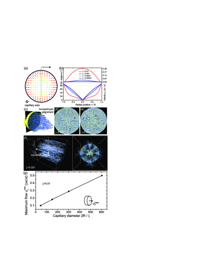
The escaped active flow has, as for the homogenous capillary, a complex in-plane secondary flow. A lattice of vortices forms, with the number of vortices depending on the activity: 8 vortices for (Fig. 3d) and 16 vortices for (Fig. 3e). Figure 3f depicts the primary flow along direction and the secondary flow in the plane by showing flow streamlines. This reveals helical flow motifs, i.e. a lattice of vortices with a distinct pitch. The pitch of the active vortices is for . The helical flow is reminiscent of cytoplasmic streaming in plant cells goldstein08 .
We next present results to determine the scaling of the active flow with the physical size of the capillary. Figure 3g shows the maximum flow velocity , in the centre of the capillary and along the capillary axis , for various diameters of the capillary at a given . The dependence is to good approximation linear, indicating a predominantly Poiseuille-like flow regime for the escaped active flow. The maximum velocity of a general isotropic fluid in a circular channel scales as , where is an effective body force driving the flow, e.g. a pressure drop per unit length of a capillary . Indeed, the active contribution in the generalised Navier-Stokes equation (2) and (4) can be extracted as an effective force from the active stress tensor , where assuming scalalability of the scale independent coordinates have been introduced. By writing , the linear scaling of is obtained, in agreement with the simulation results in Fig. 3g. Importantly, the escaped active nematic orientational profile is well scalable in space and thus gives linear , which is not necessarily true for other active nematic geometries or profiles. Note also that the slope of the curve is proportional to , and could be used to measure this ratio in active nematic materials. Indeed using an alternative viscosity measurement the strength of the activity could also be determined, and the full relation between and (not only the proportionality) could be found by measuring at different ratios, e.g. by changing the temperature, yet retaining the escaped nematic profile.
As experiments on active material in microchannels are increasingly feasible, there are several possible applications for our results. Flow patterns similar to those seen here may emerge in dense suspensions of swimmers confined to microfluidic channels which have a preferred orientation relative to the surface berke08 . Dense suspensions of active colloids provide another possible relevant experimental system theurkauff12 . Moreover similar flow patterns are seen in systems of collectively moving microtubules sumino12 .
In conclusion, we have demonstrated the richness of active nematic flow and orientational profiles in a cylindrical capillary tube. The physical behaviour depends strongly on the surface boundary conditions imposed on the director field: we considered homogenous planar, circular planar, and homeotropic (perpendicular) anchoring. The active flow emerged above a threshold in the activity for intrinsically homogeneous orientational profiles, but at for intrinsically inhomogenous director fields. The primary active flow developed along the capillary, but with intricate secondary flows, consisting of an array of velocity vortices. At high activities, bidirectional primary flow was found, indicating multiple activity modes which are observed to be (meta)stable relative one to another. Topological defects imposed by the boundary conditions in this extensile active nematic study were shown to act as effective local pumps for the flow, with their topological structure determining the pumping direction. We demonstrated the escape of the active flow and active defects into the third dimension, showcasing the importance of the dimensionality in active materials, and providing a possible route to measuring the activity of active suspensions.
M. R. acknowledges support of the EU under the Marie Curie Programme ACTOIDS.
References
- (1) T. Sanchez, et al, Science 333, 456 (2011).
- (2) D. L. Koch, G. Subramanian, Annu. Rev. Fluid Mech. 43, 637 (2011).
- (3) A. Sokolov, et al, Phys. Rev. Lett. 98, 158102 (2007).
- (4) I.H.Riedel, K.Kruse, J.Howard, Science 309, 300 (2005).
- (5) S. Ramaswamy, Annu. Rev. Conden. Mat. Phys. 1, 323 (2010).
- (6) H. P. Zhang, et al, Proc. Natl. Acad. Sci. USA107, 13626 (2010).
- (7) G. H. Koenderink, et al, Proc. Natl. Acad. Sci. USA 106, 15192 (2009).
- (8) R. Dreyfus, et al, Nature 437, 862 (2005).
- (9) N. Leoni, et al, Soft Matter 5, 472 (2009).
- (10) F. J. Nedelec, et al, Nature 389, 305 (1997).
- (11) A. Cavagna, et al, Proc. Natl. Acad. Sci. USA 107, 11865 (2009).
- (12) Y. Katz, K. Tunstrom, et al, Proc. Natl. Acad. Sci. USA 108, 18720 (2011).
- (13) C. A. Kruelle, Rev. Adv. Mater. Sci. 20, 113-124 (2009).
- (14) C. Dombrowski, et al, Phys. Rev. Lett. 93, 098103 (2004).
- (15) L. Giomi, et al, Phys.Rev. Lett. 106, 218101 (2011).
- (16) S. Sankararaman, S. Ramaswamy, Phys. Rev. Lett. 102, 118107 (2009).
- (17) T. Vicsek et al., Phys. Rev. Lett. 75, 1226 (1995).
- (18) J. Toner and Y. Tu, Phys. Rev. Lett. 75, 4326 (1995).
- (19) R. A. Simha and S. Ramaswamy, Phys. Rev. Lett. 89, 058101 (2002).
- (20) K. Kruse, et al, Phys.Rev. Lett. 92, 078101 (2004).
- (21) Y. Hatwalne, et al, Phys. Rev. Lett. 92, 118101 (2004).
- (22) G. Luca, C. M. Marchetti, Soft Matter 8, 129 (2012).
- (23) H.H. Wensink, et al, Proc. Natl. Acad. Sc. (USA), 109, 14308 (2012).
- (24) Z. Dogic, private commun.
- (25) N. H. Mendelson, et al, J. Bacteriol. 181, 600 609 (2009).
- (26) D. Saintillan and M. J. Shelley, Phys. Rev. Lett. 99, 058102 (2007); Phys. Rev. Lett. 100, 178103 (2008).
- (27) C. W. Wolgemuth, Biophys. J. 95, 1564 (2008).
- (28) R. Voituriez, J. F. Joanny, and J. Prost, Europhys. Lett. 70, 404 (2005).
- (29) D. Marenduzzo, E. Orlandini, J.M. Yeomans, Phys.Rev. Lett. 98, 118102 (2007).
- (30) S. M. Fielding, D. Marenduzzo, M. E. Cates, Phys.Rev. E 83, 041910 (2011).
- (31) J. Elgeti, M. E. Cates, D. Marenduzzo, Soft Matter 7, 3177 (2011).
- (32) F. G. Woodhouse, R. E. Goldstein, Phys. Rev. Lett. 109, 168105 (2012).
- (33) A. N. Beris and B. J. Edwards, Thermodynamics of Flowing Systems, (Oxford University Press, Oxford, 1994).
- (34) C. Denniston, et al, Philos. Trans. R. Soc. London, Ser. A 362, 1745 (2004).
- (35) E. Orlandini, et al, Mol. Cryst. Liq. Cryst. 494, 293 308 (2008).
- (36) R. Voituriez, J. F. Joanny, and J. Prost, Phys. Rev. Lett. 96, 028102 (2006).
- (37) R. E. Goldstein, I. Tuval, J.-W. van de Meent, Proc. Natl. Acad. Sci. USA 105, 3663-3667 (2008).
- (38) A.P. Berke, et al, Phys. Rev. Lett. 101, 038102 (2008).
- (39) I. Theurkauff, et al, Phys. Rev. Lett. 108, 268303 (2012).
- (40) Sumino, et al, Nature 483, 448 (2012).