Evolution of Warped Accretion Disks in Active Galactic Nuclei. I. Roles of Feeding at the Outer Boundaries
Abstract
We investigate the alignment processes of spinning black holes and their surrounding warped accretion disks in a frame of two different types of feeding at the outer boundaries. We consider (1) fixed flows in which gas is continually fed with a preferred angular momentum, and (2) free flows in which there is no gas supply and the disks diffuse freely at their outer edges. As expected, we find that for the cases of fixed flows the black hole disk systems always end up aligning on timescales of several yr, irrespective of the initial inclinations. If the initial inclination angles are larger than , the black hole accretion transits from retrograde to prograde fashion, and the accreted mass onto the black holes during these two phases is comparable. On the other hand, for the cases of free flows, both alignments and anti-alignments can occur, depending on the initial inclinations and the ratios of the angular momentum of the disks to that of the black holes. In such cases, the disks will be consumed within timescales of yr by black holes accreting at the Eddington limit. We propose that there is a close connection between the black hole spin and the lifetime for which the feeding persists, which determines the observable episodic lifetimes of active galactic nuclei. We conclude that careful inclusion of the disk feeding at the outer boundaries is crucial for modeling the evolution of the black hole spin.
Subject headings:
accretion, accretion disks — black hole physics — galaxies: active1. Introduction
The current hierarchical framework of galaxy formation and evolution predicts that, in addition to secular evolution, repeat galaxy mergers trigger activities of supermassive black holes (SMBHs) located at the galactic center and hence their growth (e.g., Benson & Bower 2010). As such, fuel feedings channeled onto SMBHs most likely proceed at episodic and random phases (e.g., Martini 2004; King & Pringle 2006; Wang et al. 2006, 2008, 2009; Li et al. 2010). This picture is further reinforced by various lines of observations, such as misaligned active galactic nuclei (AGNs) with respect to their host galaxies (Kinney et al. 2000; Gallimore et al. 2006; Muñoz Marín et al. 2007; Shen et al. 2010), and as well as by numerical simulations (e.g., Hopkins et al. 2012 and references therein). Previous studies on the cosmological evolution of the radiative efficiency () of accretion according to the Sołtan’s (1982) argument and formulated by the equation, found that decreases with cosmic time since redshift , strongly implying that random accretion takes place upon the SMBHs (Wang et al. 2009; Li et al. 2011, 2012; see also the discussion of Zhang et al. 2012). A similar inference has recently been highlighted from the semi-analytical modeling on SMBH demography by Volonteri et al. (2012). In this context, warped accretion disks are ubiquitous in AGNs.
A misaligned accretion disk around the central spinning black hole undergoes Lense-Thirring precession arising from the gravitomagnetic effects, of which the rate falls off rapidly with the radius to the hole (e.g., Hartle 2003). The presence of viscosity combined with such differential precession will induce the inner portion of the disk to align or anti-align its orbital angular momentum with the spin axis of the hole out to a transition radius, beyond which the disk retains its initial inclination (Bardeen-Petterson effect; Bardeen & Petterson 1975). In the meantime, associated with disk precession, the black hole suffers an equal and opposite gravitomagnetic torque that causes it to precess as well. Under mutual interaction and warp propagation in the disk, this composite system tends to restore full axisymmetry with the entire disk ultimately aligned or anti-aligned with the hole (King et al. 2005). The characteristic timescale and the final state of the system (alignment or anti-alignment) depend on the black hole mass and spin and the properties of the accretion disk.
Based on the angular momentum conservation, King et al. (2005) demonstrated that the disk will end up anti-aligned with the hole if the angular momentum of the hole () dominates over that of the disk (). This refreshes previous analytical studies on the grounds that the disk has an infinite extension and is continuously fed (Scheuer & Feiler 1996; Martin et al. 2007), and has been incorporated into the black hole spin modeling in the context of hierarchical cosmology (King et al. 2008; Lagos et al. 2009; Fanidakis et al. 2011; Barausse 2012). However, while is accurately defined, the meaning of is not as well defined in King et al. (2005), leading to its interpretation varying among subsequent studies.
It is commonplace that, in the outer region, the accretion disk likely becomes self-gravitating, fragments into clumps, and probably manifests itself as a star-forming region (e.g., Paczynski 1978; Shlosman & Begelman 1987; Collin & Zahn 1999; Goodman 2003; Wang et al. 2010). The feedback from the stellar radiation or the resultant supernova explosions embedded in the disk acts to excite turbulence that continues to deprive gas of angular momentum (Wada & Norman 2002; Kawakatu & Wada 2008; Kumar & Johnson 2010; Wang et al. 2010). In this case, it is expected that gas will be continually fueled into the accretion disk from the outer region (e.g., circumnuclear disk or torus) for the duration of the AGN’s lifetime. The practical implications are twofold: an outer edge of the disk limited by its own self-gravity exists so that the angular momentum of the disk can be properly defined, and there is a gas supply with specified angular momentum at this outer edge.
With the above inference, a comprehensive study of the alignments/anti-alignments between black holes and their warped accretion disks is essential, in particular considering the increased focus on modeling the black hole spin across cosmic time. In this work, we revisit this issue by numerically solving the evolution equation set of black holes and accretion disks in a practical sense. The paper is organized as follows: Section 2 describes the evolution equation set for a black hole and its warped accretion disk. Section 3 surveys the properties of warped accretion disks from the theoretical point of view. Section 4 shows the numerical scheme and sets up the boundary conditions and initial conditions for solving the evolution equation set. The results are then presented in Section 5. The implications of our results on SMBH spin evolution and the uncertainties in our calculations are discussed in Section 6. Conclusions are summarized in Section 7.

2. Basic Evolution Equations
The dynamics of warped disks have been studied extensively through theoretical analysis (e.g., Papaloizou & Pringle 1983; Pringle 1992; Papaloizou & Lin 1995; Ogilvie 1999, 2000; Lubow et al. 2002) and numerical simulations (e.g. Larwood et al. 1996; Nelson & Papaloizou 1999, 2000; Dotti et al. 2010; Lodato & Price 2010; Nixon & King 2012; Nixon et al. 2012; McKinney et al. 2013). Adopting the standard prescription of disk viscosity, warp propagation in the disk is characterized into two regimes depending on the relative importance of pressure forces and viscous forces. For a nearly inviscid or sufficiently thick disk such that the dimensionless viscosity coefficient is smaller than the disk aspect ratio , the warp propagates as bending waves at a velocity related to the speed of sound (Papaloizou & Lin 1995); whereas in the regime , the warp evolves in a diffusive fashion. Here is the semithickness of the disk.
We focus our attention on a thin and viscous accretion disk with a Keplerian rotation (), the most likely case for accretion disks in AGNs (Pringle 1999). The evolution of such warped disks can be completely described by the angular momentum density of the disk as (Ogilvie 1999)
| (1) | |||||
where , denotes the direction vector, is the mass surface density, is the angular velocity, is the gravitomagnetic torque responsible for the Lense-Thirring precession, and is the radial velocity given by
| (2) |
Here the internal viscous torque of the disk fluid has been distinguished into three kinds associated with three effective viscosities, respectively (Bardeen & Petterson 1975; Ogilvie 1999). The first viscosity, , governs the usual azimuthal shear due to the differential rotation; the second viscosity, , governs the vertical shear that acts to diffuse the warp throughout the disk; and the third viscosity, , governs a torque component that tends to create the disk ring process if it is misaligned with its neighbors. The later two viscosities disappear in a flat disk. It is worth pointing out that Equation (1) remains valid for large amplitude warp (Ogilvie 1999).
By analyzing the internal non-linear dynamics of warped accretion disks, Ogilvie (1999) formulated the effective viscosities and showed that they generally depend on the amplitude of the warp. For the sake of simplicity, we make use of the first-order approximations as follows
| (3) |
and . As a result, the warp propagates in the disk on a timescale of an order of
| (4) |
where is the usual viscous timescale.
In the weak field limit, the gravitomagnetic torque due to frame dragging has a form of (Bardeen & Petterson 1975)
| (5) |
where is the angular momentum of the hole with its modulus , is the spin parameter, is the mass of the black hole, is the gravity constant, and is the speed of light. Due to the mass accretion and the gravitomagnetic torque exerted by the warped accretion disk, the angular momentum of the black hole evolves with time as
| (6) |
where is the mass accretion rate through the inner edge of the disk , which is determined by the marginal stable orbit, and is the specific angular momentum carried by matter at the inner edge.
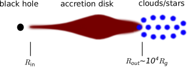
To study the roles of disk feeding, we consider two classes of accretion models to mimic the realistic accretion disks, as schematically shown in Figure 1. In the left panel, an outer clumpy region composite of clouds and/or stars continues to channel gas to the accretion disk from the outer environment (e.g., circumnuclear disk or torus). As stated above, the feedback from stellar radiation and supernova explosions are the potential mechanism responsible for exciting turbulence and viscosity, acting to transport the angular momentum of accreting matter (Wada & Norman 2002; Kumar & Johnson 2010; Wang et al. 2010). We denote this case as “fixed flows” because the angular momentum of gas supply at the outer edge has a preferred direction. By contrast, the right panel of Figure 1 shows the other class of outer boundary conditions, in which there is no gas supply and the disk diffuses freely at its outer edge. We therefore denote this case as “free flows”. Before numerically solving the above equations, we endeavor to explore the properties of warped accretion disks from a theoretical point of view in the next section.
3. Warped Accretion Disks
We start by specifying the accretion disk model used in this paper generally following Collin-Souffrin & Dumont (1990). To simplify the theoretical analysis and numerical calculations below, we parameterize accretion disks with a Keplerian rotation of , and a constant aspect ratio of . The mass surface density of the disk obeys , where is a coefficient determined by setting the total disk mass at a fraction of the black hole mass , and is an index to enforce the mass accretion rate of to a constant at a large radius as for a flat disk. The outer edge of the disk is located where self-gravitating becomes important, whose value depends on the mass accretion rate and black hole mass (e.g., Goodman 2003; King et al. 2008). In what follows, for illustration purposes, we adopt fiducial values of , , , , , and , where is the gravitational radius.
3.1. Transporting Angular Momentum
In planar accretion disks, matter gradually falls inward the central black hole, whereas nearly all of the angular momentum is transported outward due to viscosities (Frank et al. 1992). This remains valid for warped accretion disks (Scheuer & Feiler 1996). The difference is that gravitomagnetic interactions of the hole and the disk induce extra transfers of angular momentum between them. This transfer rate depends on the Lense-Thirring precessing rate and warp propagation velocity. There exists a transition radius where the Lense-Thirring precessing timescale is comparable with the warp propagation timescale, which is usually denoted by a “warp radius”.
Within the warp radius, the Lense-Thirring precessions are dominant. Viscosities damp out the differential precessions rapidly, giving rise to an inner flat disk. It is easy to verify: if initially the angle of the disk and the hole is smaller than , the inner flat disk is aligned with the hole. By contrast, if the angle is larger than , the inner flat disk is anti-aligned. In the region around the warp radius, the incoming matter is inclined toward the inner flat disk, and the associated angular momentum is transferred to the hole through gravitomagnetic interaction. Further beyond the warp radius, warps propagate outward efficiently and the misaligned angular momentum is transported outward as well.
Since the gravitomagnetic torque integrated over the whole disk in Equation (6) is always orthogonal to , it can be expressed in the form of (King et al. 2005)
| (7) |
where a hat symbol on top of a vector stands for the corresponding direction vector, and are time-dependent coefficients, and
| (8) |
is the total angular momentum of the disk. Here, the first term corresponds to the precessions and the second term corresponds to changes in the angle between the hole and the disk. Below we will numerically demonstrate that and are generally positive (see also Scheuer & Feiler 1996; King et al. 2005; Martin et al. 2007).
3.2. Magnitude Estimates
In in previous section, we demonstrate that the characteristic extension of warps is determined by the timescales for warp propagation given by Equation (4) and for the local Lense-Thirring precessing (Scheuer & Feiler 1996). By equating these two timescales, one obtains the warp radius . Using the formulation of and the fiducial values of parameters, is of the order of
| (9) |
Considering that the Lense-Thirring torque in Equation (5) falls off rapidly with the radius in proportion to , the major contribution it has on the hole comes from the region of the disk around . As a result, the torque that the disk exerts on the hole approximates
| (10) |
where the mass accretion rate is used for simplicity. This results in a timescale for the alignment between the hole and the whole disk (see also Perego et al. 2009)
| (11) | |||||
where is the growth timescale for a black hole accreting at a rate of . Again, with the help of the approximation , one can estimate the mass accretion rate as
| (12) | |||||
and the growth timescale yr. We note that this estimated accretion rate is generally equal to the Eddington limit.
If there is no gas supply to the accretion disk, the disk will be consumed on a timescale of an order of
| (13) |
which is independent of and . As can be seen from Equation (11), once the disk is gradually depleted (without gas replenishment), the resulting decreases of surface density and the mass accretion rate will significantly prolong the alignment processes. The timescale for warp propagation throughout the disk in Equation (4) is
| (14) | |||||
The total angular momentum of the disk is
| (15) |
This gives a ratio of over :
| (16) |


3.3. Alignments and Anti-alignments
In this section, we qualitatively study what controls the final configuration of black hole-disk systems, i.e., alignments or anti-alignments, inspired by the arguments of King et al. (2005). As shown in the previous section, the (anti-)alignment timescale is generally orders of magnitude less than the growth timescale for black holes. Therefore, the accretion contribution to the changes of in Equation (6) can be safely neglected. By denoting as the angle between and and using Equation (7), we have
| (17) |
In the meantime, above the time derivative can be alternatively written
| (18) |
where we apply the fact that the gravitomagnetic interaction only modifies the direction of but keeps its modulus unchanged (i.e., ). A simple algebra manipulation yields
| (19) |
Obviously, besides the gravitomagnetic interaction, the evolution of the inclination angle depends on how the angular momentum of the disk changes.
According to the different types of disk feeding in the outer edges as illustrated in Figure 1, we distinguish the two following cases.
1) Fixed flows. If the disk is steadily fed and maintains a preferred angular momentum distribution, one shall expect , and therefore , to remain somewhat unchanged with time. As a result, Equation (19) is simplified into
| (20) |
This means that, as found by previous intensive studies (Scheuer & Feiler 1996; Martin et al. 2007; Perego et al. 2009), a continuously fed disk always drives the hole to align with it regardless of the initial inclination.
2) Free flows. For disks without replenishment, the total angular momentum of the system () is conserved. With the help of Equation (7), it is easy to derive the following equation (see also King et al. 2005)
| (21) |
Note that here the coefficient is time-dependent. Because is positive, once initially , i.e., , the right hand side in the above equation is never smaller than zero. Therefore, will decrease continuously and the system ends up aligned. For , there exist two subcases:
-
•
if , the inclination decreases;
-
•
while on the contrary if , the inclination increases toward .
In real situations, generally decreases with time due to the internal viscous dissipation, and subsequently, the ratio can transit from the former subcase to the latter. Therefore, the above conditions are indeed instantaneous for the behavior of the inclination. We next dig into exploring the detailed alignment/anti-alignment processes with help from numerical calculations.
4. Numerical Scheme
Numerically solving Equations (1) and (6) gives the self-consistent evolution of the black hole accretion disk system. For this purpose, we implement a differencing scheme following Pringle (1992), but with some different treatment tricks. A detailed description of our differencing scheme and robust tests of the code are given in Appendices A and B, respectively.
In order to produce the free-torque conditions in the inner boundary, we enforce such that the mass and angular momentum that reaches the inner boundary are removed, resulting in accretion onto the hole (see also Bregman & Alexander 2012; Nixon & King 2012). Accordingly, the initial surface density is setup by adding an extra factor to allow for the torque-free condition (Frank et al. 1992), namely,
| (22) |
where is the inner edge of the disk. In consideration of the inner portion of the disk aligned/anti-aligned with the hole, we set at .
Given an initial inclination angle of , we generate the initial distribution of the direction of disk rings as
| (23) |
For this configuration, we presume that initially the black hole spin is oriented toward the axis.
The outer boundary conditions at are treated differently for fixed flows and free flows.
-
•
Fixed flows. Gas supply at the outer edge inherits a specified direction of angular momentum, that is to say keeps unchanged throughout. The surface density at the outer boundary is fixed to . This yields a mass supply through the outer boundary at a rate given by Equation (12).
-
•
Free flows. Angular momentum freely diffuses outward through . To ensure a correct treatment of the diffusion at , we choose the outer grid boundary well beyond the outer disk edge (e.g., ).
In our calculations, without specified otherwise, we adopt the fiducial values , , , , , and the initial black hole mass and spin . In principle, is determined by the marginal stable orbit of the central black hole. However, since the inner portion of the disk is always aligned/anti-aligned with the hole, the location of does not affect the gravitomagnetic torque and hence the alignment rate. Moreover, a relatively larger helps to improve the time consumption of the computations in view of the timestep size limited by viscous timescales (see Equation (4)). To assess the processes of alignments and anti-alignments, we adjust the two free parameters: the mass fraction of the disk to the black hole , which determines the surface density of the disk in Equation (22) and hence the mass accretion; and the initial inclination angle between the disk and the hole . We setup the grid with 202 points and evolve the equation set for a time of , where yr is the viscous time at (see Appendix A for details).
5. Results
5.1. Evolution of Warped Accretion Disks
We define the inclination of disks at radius with respect to black holes as
| (24) |
In Figure 2, we illustrate how the shape of warped accretion disks evolves with times for free flows. The initial inclination angles are in the upper panel and in the bottom panel, respectively. We can find that an inner flat disk rapidly forms for all cases and is aligned to the black hole for and anti-aligned for . The size of the inner flat disk continuously grows until roughly , corresponding to the warp radius defined in Equation (9). Warp propagation reaches the outer edge of the disk within a timescale of , consistent with the estimate from Equation (14). The disk for gradually approaches full alignments; however, the alignment rate is prone to severe attenuation with time. The disk inclination is almost unchanged from to . At the end of the numerical calculation , the disk maintains an inclination of at the outer edge. Henceforth, it hardly aligns with the black hole fully. This is because of a severe depletion of the surface density due to mass accretion (see Equation (13)). In Figure 3, it is verified that the mass accretion onto the black hole decreases rapidly with time by more than one order of magnitude as a result of disk depletion. This implies that if there is no gas supply, the luminosity of the accretion disk will fade out less than yr. We further calculate the components of the gravitomagnetic torque that the whole disk exerts on the hole and as defined in Equation (7). As shown in Figure 4, it is confirmed that irrespective of the initial inclinations, both and are positive. Moreover, and are in the same order of magnitude (Scheuer & Feiler 1996; King et al. 2005; Martin et al. 2007).
The system for evolves toward anti-alignment in a similar fashion, as expected since initially . However, the inclination at has changed only from to at the end of the calculation, which is very inefficient compared to the case of . The corresponding reason is that, as shown in Equation (21), the change of from the gravitomagnetic torque is proportional to . Its value for is smaller by an order of magnitude than that for .

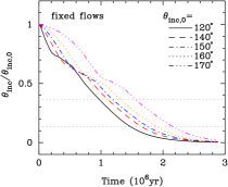
The cases for fixed flows are illustrated in Figure 5. By analogy to free flows, warps spread to the outer boundary within ; however, the subsequent evolution is somewhat different. The system with quickly achieves full alignment after a time less than . For , the disk shape shows complicated behaviors. The inner anti-aligned angular momentum is transported outward by warp propagation and confronts the angular momentum carried by the feeding matter. As a result, an abrupt discontinuity of the inclination appears and the disk breaks into two parts: an inner nearly anti-aligned portion and an outer misaligned portion (see also Lodato & Pringle 2006; Nixon & King 2012; Nixon et al. 2012). The location of the discontinuity transfers inward with time and the inner portion will be eventually swallowed by the hole due to mass accretion. In the meantime, the black hole is driven to align with the outer portion progressively. Around the time , after the inner anti-aligned portion of the disk is consumed, the newly formed inner disk turns to be aligned with the black hole. At the end of the calculation , there is complete alignment between the disk and the black hole.

The mass accretion rates onto the black holes for fixed flows are plotted in Figure 6. From Equation (2), the role of warping increases the inflow velocity and therefore enhances the mass accretion rate. As expected, for , the accretion rate onto the hole () has a mildly decreasing trend by a factor of two at the beginning in response to the approaching alignment of the system. Then it maintains a steady value of , equal to the gas supply rate at the outer boundary. Quite differently, for there exist two peaks of the mass accretion rate at times and due to the large magnitude of warping developed at these moments (see the bottom panel of Figure 5). While the inner anti-aligned disk portion is being consumed, the accretion rate becomes significantly attenuated by orders of magnitude and reaches the minimum () around . Nevertheless, the mass accretion onto the hole eventually approaches a steady rate, the same as for . It is worth pointing out that the black hole undergoes retrograde accretion for a time , after which it transits to prograde accretion.


5.2. Alignment and Anti-alignment Timescales
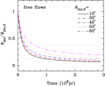
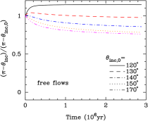
Figure 7 plots the evolution of the inclination angles between the black hole and the disk for two classes of accretion flows. Here the inclination angle is defined by
| (25) |
where is the total angular momentum of the disk. The upper left panel shows against time with from bottom to top for free flows. The timescales that the inclination angle decreases to of its initial value generally lie at several yr, consistent with the magnitude estimate in Equation (11). However, the decaying rate of the inclination angle rapidly slows down with time because of the depletion of the disk (almost all of the disk angular momentum is transported to the large radius). After yr, the inclinations for all the cases are prone to be frozen, indicating that the disk shall hardly approach complete alignment. This further confirms the results in the previous section. The upper right panel plots with from top to bottom for free flows. Overall, although quite inefficient, the inclination angles have a tendency to approach except for , implying a trend of anti-alignment between the hole and the disk. The system for tends toward alignment instead of anti-alignment because is always retained throughout the calculation (see Section 3.3). Interestingly, there is an increasing trend at the beginning for and , because initially, which, however, transits to later on. Again, the alignment rates are significantly slower compared with the counterparts in the upper left panel.
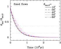
The bottom panels of Figure 7 show the results for fixed flows. The timescales where decreases to of its initial value are also generally several yr for (bottom left panel) and almost insensitive to . Within a time of , the entire disks have been in complete alignment with the holes. In the bottom right panel, decreases with time even though as was expected through the previous theoretical analysis. There are inflection points in the evolution curves of that correspond to when the disks break into two parts as illustrated in Figure 5. Generally, the timescales of the decaying rate for (bottom right panel) are relatively longer compared to these for (bottom left panel) due to the same reasons for free flows. However, because the disks are replenished and therefore the gravitomagnetic torques from the disks are not attenuated, the decreasing rates of are clearly more rapid than their counterparts (top right panel) for free flows.
In summary, for fixed flows in which disks are continually fed, alignments always occur regardless of the initial inclination. The alignment timescale is of an order of yr. For free flows in which there is no gas supply, both alignments and anti-alignments could occur. However, as a result of the notable depletion of the disk’s surface density at a timescale of yr, the alignment/anti-alignment rate is significantly reduced, leading the disks to be not completely aligned/anti-aligned.
5.3. Conditions for Anti-alignments
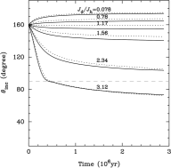
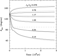
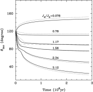
Previous sections show that anti-alignment between black holes and disks is possible only when the initial inclination angle is for free flows. To assess how the final configuration of the system depends on the free parameters, in this section we evolve the equation set given different parameters and only for free flows. We note that the parameter determines the initial total angular momentum of the disks as in Equation (16). Figure 8 plots the evolution of inclination angle between and with 0.1, 1, 1.5, 2, 3, 4, and 6, corresponding to the initial ratios , 0.78, 1.17, 1.56, 2.34, and 3.12, respectively. The initial inclination angles are , , and from top to the bottom panel. Since gas diffuses outward through for free flows, there is an outflow of angular momentum at accordingly. Here includes these aspects of angular momentum. For comparison purposes, we also calculate the inclination angles in terms of the angular momentum of the disk just within , plotted by dotted lines in Figure 8. As can be seen, the evolution trends of depend both on the ratios and the initial inclinations. Specifically, there are three prominent features as follows.
1) Consistent with the prediction in Section 3.3, the inclination angles generally go up when the initial ratios , but otherwise, drop off. We note that in the middle panel of Figure 8 the inclination of the system with an initial ratio , larger than , descends mildly at the very beginning and then increases toward . This is because the ratio rapidly decreases to .
2) The inclination for begins to enter when the initial ratio is larger than . This means that the system will approach alignment, and most importantly, the black holes undergo a transition from retrograde to prograde accretion. Similarly, the critical ratios for and are and , respectively.
3) Without replenishment, the disks are greatly depleted on a timescale of yr. As a result, the gravitomagnetic torques are reduced with time and the inclination angles are almost frozen to values not equal to or at the end of calculations. In other words, the systems hardly achieve full alignment or anti-alignment.
On the basis of the angular momentum conservation of the system (free flows in the present study), King et al. (2005) proposed that anti-alignments will occur provided that the initial angle between the angular momenta of the hole and the disk satisfy . Applying this formula to the present cases, for , anti-alignment occurs when the ratio obeys initially; for and , the corresponding critical ratios are and , respectively. Our results in Figure 8 are in considerable disagreement with these values. We ascribe such discrepancy to the neglect of the disk’s depletion in the previous work. The ratio between the timescales for (anti-)alignments and the disk’s depletion is of an order of unity for fiducial parameters from Figure 7. During accretion onto the black hole, the disk’s mass is gradually consumed and the majority of the disk’s angular momentum is transported to the large radius (Frank et al. 1992). Note that the gravitomagnetic torque is in proportion to , therefore the (anti-)alignment rate will be greatly reduced. This effect leads to some systems with ratios of still maintaining at the end of the calculations in Figure 8.
6. Discussions
6.1. Implications for Black Hole Spin
In addition to fueling black holes, accretion also adds angular momentum carried by matter to black holes and accordingly modifies their spin. How spin changes depends on the orbits at the inner edge of the accretion disks. Specifically, if the disk is aligned with the black hole, prograde accretion will spin up the hole; otherwise, retrograde accretion spin down the hole. The black hole will become maximally rotating () when its mass is doubled provided prograde or alternative retrograde accretion is preferably retained for a sufficient amount of time (Thorne 1974). In view of the episodic and random activities of black hole accretion (Wang et al. 2006; Li et al. 2010), it is crucial to model the spin evolution whether the accretion in each episode proceeds progradely or retrogradely.
Our results obtained above imply that the configurations of the accretion disks depend on feeding them at the outer boundaries. If the disks are continually fed for a long enough lifetime (say, e.g., yr), alignments always occur. In this case, prograde accretion is the dominated fashion. We expect that after a series of activities, black holes will be close to maximal rotation. On the other hand, if there is no gas feeding, both alignments and anti-alignments are possible, depending on the initial inclinations and the ratios (see Section 5.3). One has to follow the probabilities of alignments and anti-alignments over episodes using the method presented here to determine spin evolution. An incorporation of the present calculations into semi-analytical models of galaxy formation and evolution will shed light on the existing studies in the field (e.g., Lagos et al. 2009; Fanidakis et al. 2011; Barausse 2012; Volonteri et al. 2012; Dotti et al. 2013), and provide more realistic information on SMBH spin.
Note that black hole accretion only lasts a lifetime of yr as a result of disk depletion without feeding.111The lifetime can be generally estimated as follows: for black holes accreting at the Eddington limit , where , the accretion disks with masses of will be consumed at yr, where . Indeed, the lifetime of feeding disks directly determines the observable episodic lifetimes of AGNs. In this sense, observational measurements of the episodic lifetimes of AGNs can place useful constraints on the SMBH spin evolution. Unfortunately, thus far the episodic lifetime of AGNs remains elusive though some endeavor has been put forth (see a review of Martini 2004). The most compelling method—proximity effects estimated the episodic lifetimes in a broad range of yr, varying from study to study (Kirkman & Tytler 2008; Gonçalves et al. 2008; Furlanetto & Lidz 2011). Future observations from large sample quasar surveys with a variety of techniques would offer promising measurements on the episodic lifetimes and help to understand the cosmological evolution of SMBH spin.
On the other hand, we turn over the issue so as to constrain the episodic lifetimes of AGNs from the otherwise obtained SMBH spin evolution. Recently, quantifying the radiative efficiency of mass accretion through SMBH demography strongly suggests that SMBHs are spinning down with cosmic time since (Wang et al. 2009; Li et al. 2011, 2012; see also the discussion of Zhang et al. 2012). Combined with the present results, this indicates that the episodic lifetime of AGNs must not exceed several yr and probably have cosmological evolution as well. More detailed modelings on the connections between SMBH spin evolution and the episodic lifetime of AGNs are highly deserved in future works.
It is worth stressing that we presume black holes to be accreting at the Eddington limit in the calculations. The timescale for (anti-)alignments between the disks and the holes is in proportion to the reciprocal of the mass accretion rate (see Equation (11)). Therefore, if the presumed mass accretion rate is relaxed, the above proposed limit on the AGN lifetime changes in the same manner accordingly.
6.2. Uncertainties
In our calculations, the inner edge of the disk is fixed at . Considering that the inner portion of the disk within always remains aligned with the hole, this does not affect the gravitomagnetic torque on the hole and therefore the alignment rate. On the other hand, during the alignment course, the accreted mass and angular momentum are negligible with those of the black hole. Hence, the results presented in this paper are insensitive to the location of the inner boundary. For the sake of simplicity, the disk’s outer edge (limited by the self-gravitating) is fixed at . In reality, the self-gravitating radius depends on the accretion rate, but generally lies at a range of for standard accretion disks (e.g., Goodman 2003; King et al. 2008). The location of just determines the ratio of as in Equation (16), but does not affect the gravitomagnetic torque and (anti-)alignment timescale as in Equations (5) and (11). The overall results remain unchanged.
The viscosities for accretion disks are treated using the first-order approximations given by Ogilvie (1999). The nonlinear fluid effects that appear for large amplitude warp would modify the expressions of the effective viscosities (Ogilvie 1999; Lodato & Price 2010). We expect this to become significant when the disks break as shown in the bottom panels of Figure 5. In this case, however, it is unclear whether the evolution equation set adopted here remains adequate. Dedicated investigations, including nonlinear fluid dynamics, are beyond the scope of the present study. We defer this to future sophisticated numerical simulations.
Finally, we consider the accretion disks under the Newtonian timespace and treat the gravitomagnetic interaction in the weak-field limit (the Lense-Thirring precession). The general relativistic calculations are of somewhat less importance because the warp radius is far beyond the gravitational radius (see Equation (9)).
7. Conclusions
We numerically solve the evolution equation set of spinning black holes and their warped accretion disks. To mimic the realistic accretion processes, we consider two classes of accretion disks in terms of the outer boundary conditions: fixed flows for which the disk is continually fed with a preferred angular momentum through its outer edge; and free flows for which there is no gas supply and the disk diffuses freely at its outer edge (see Figure 1). Our main results are as follows.
-
1.
For disks continually fed, alignments between the holes and disks always occur at a time of several yr regardless of the initial inclinations. If the initial inclination angles are , black hole accretion transits from retrograde fashion to prograde fashion after a time of several alignment timescales. The mass growths during these two phases are comparable.
-
2.
For disks without a gas supply, both alignments and anti-alignments are possible, depending on the initial inclinations and the ratios . It is worthwhile to point out that the lifetime of black hole accretion at the Eddington limit in such cases last yr due to the depletion of the accretion disks. This has important influences on the (anti-)alignment processes.
-
3.
Black hole spin is closely linked to the manners of mass accretion, namely, progradely or retrogradely. Careful inclusion of disk feeding at the outer boundaries is highly important to modeling spin evolution in the context of episodic and random activities of SMBHs. The episodic lifetime of AGNs, which can be measured with a variety of techniques, is directly determined by the lifetime of disk feeding. We therefore propose that there would be a close connection between the black hole spin and the episodic lifetime of AGNs, which deserves a comprehensive investigation in future works.
Appendix A A. Differencing The Equation Set
We construct the differencing scheme of Equations (1) and (6) generally following Pringle (1992), but with some modifications. For the sake of completeness, we summarize our implementation here.
The spatial domain is discretized into () logarithmic grid points: , for , with the equal spacing of the logarithmic grid. The points and represent the inner and outer grid boundaries, respectively. If we define the advective velocity
| (A1) |
and use Equation (2), Equation (1) can be written as
| (A2) |
Notationally, we use a superscript to denote the timestep and a subscript to denote the spatial grid point. The differencing scheme of Equation (A2) is then built as follows (see also Bregman & Alexander 2012)
| (A3) | |||||
where is the timestep size, and the advective term is treated using upstream differencing: for , ; whereas for , . The advective velocity is calculated by
| (A4) |
Similarly, the differencing scheme of Equation (6) is built as
| (A5) |
where the mass accretion rate onto the hole is calculated as and the specific angular momentum at the inner edge is calculated as . As described in Section 4, at the inner boundary, we take , and ; at the outer boundary, for free flows, we take ; for fixed flows we take and fix . This enforces a coherent mass supply at a rate given roughly by Equation (12). The timestep size is adjusted for every step according to
| (A6) |
where
| (A7) |
| (A8) |


Appendix B B. Validity of the Numerical Code
To verify the validity of our numerical code, we perform three tests. (1) We run the code upon a flat disk ( or ) for a time of . The left panel of Figure 9 plots the surface density of the disk at the beginning and end of the calculations. There are tiny deviations less than 2% due to the dissipation of the numerical scheme. (2) For small warping, there exist analytical solutions if disks are continually fed at the outer edges, analogous to fixed flows defined in the present paper (Scheuer & Feiler 1996; Martin et al. 2007; Chen et al. 2009). We only evolve Equation (1) with a sufficient amount of time using the differencing scheme described above and obtain a steady shape of the disk. In the middle panel of Figure 9, we compare the numerically obtained inclination profile of the disk with the analytic solution given by Equation (24) in Martin et al. (2007). A complete match can be found. (3) Then initializing the disk with the above shape, we go on to evolve Equations (1) and (6) simultaneously to obtain the time-dependent inclination angle between the hole and the disk. The right panel of Figure 9 shows that our numerical calculations are in exact agreement with the analytical solutions given by Equation (52) in Martin et al. (2007). These three tests indicate a validity of our numerical code.
References
- Barausse (2012) Barausse, E. 2012, MNRAS, 423, 2533
- Bardeen & Petterson (1975) Bardeen, J. M., & Petterson, J. A. 1975, ApJ, 195, L65
- Benson & Bower (2010) Benson, A. J., & Bower, R. 2010, MNRAS, 405, 1573
- Bregman & Alexander (2012) Bregman, M., & Alexander, T. 2012, ApJ, 748, 63
- Chen et al. (2009) Chen, L., Wu, S., & Yuan, F. 2009, MNRAS, 398, 1900
- Collin-Souffrin & Dumont (1990) Collin-Souffrin, S., & Dumont, A. M. 1990, A&A, 229, 292
- Collin & Zahn (1999) Collin, S., & Zahn, J.-P. 1999, A&A, 344, 433
- Dotti et al. (2013) Dotti, M., Colpi, M., Pallini, S., Perego, A., & Volonteri, M. 2013, ApJ, 762, 68
- Dotti et al. (2010) Dotti, M., Volonteri, M., Perego, A., et al. 2010, MNRAS, 402, 682
- Fanidakis et al. (2011) Fanidakis, N., Baugh, C. M., Benson, A. J., et al. 2011, MNRAS, 410, 53
- Frank et al. (1992) Frank, J., King, A., & Raine, D. 1992, Accretion Power in Astrophysics (Cambridge: Cambridge Univ. Press)
- Furlanetto & Lidz (2011) Furlanetto, S. R., & Lidz, A. 2011, ApJ, 735, 117
- Gallimore et al. (2006) Gallimore, J. F., Axon, D. J., O’Dea, C. P., Baum, S. A., & Pedlar, A. 2006, AJ, 132, 546
- Gonçalves et al. (2008) Gonçalves, T. S., Steidel, C. C., & Pettini, M. 2008, ApJ, 676, 816
- Goodman (2003) Goodman, J. 2003, MNRAS, 339, 937
- Hartle (2003) Hartle, J. B., 2003, Gravity: An Introduction to Einstein’s General Relativity (San Francisco, CA: Addison-Wesley)
- Hopkins et al. (2012) Hopkins, P. F., Hernquist, L., Hayward, C. C., & Narayanan, D. 2012, MNRAS, 425, 1121
- Kawakatu & Wada (2008) Kawakatu, N., & Wada, K. 2008, ApJ, 681, 73
- King et al. (2005) King, A. R., Lubow, S. H., Ogilvie, G. I., & Pringle, J. E. 2005, MNRAS, 363, 49
- King & Pringle (2006) King, A. R., & Pringle, J. E. 2006, MNRAS, 373, L90
- King et al. (2008) King, A. R., Pringle, J. E., & Hofmann, J. A. 2008, MNRAS, 385, 1621
- Kinney et al. (2000) Kinney, A. L., Schmitt, H. R., Clarke, C. J., et al. 2000, ApJ, 537, 152
- Kirkman & Tytler (2008) Kirkman, D., & Tytler, D. 2008, MNRAS, 391, 1457
- Kumar & Johnson (2010) Kumar, P., & Johnson, J. L. 2010, MNRAS, 404, 2170
- Lagos et al. (2009) Lagos, C. D. P., Padilla, N. D., & Cora, S. A. 2009, MNRAS, 395, 625
- Larwood et al. (1996) Larwood, J. D., Nelson, R. P., Papaloizou, J. C. B., & Terquem, C. 1996, MNRAS, 282, 597
- Li et al. (2011) Li, Y.-R., Ho, L. C., & Wang, J.-M. 2011, ApJ, 742, 33
- Li et al. (2012) Li, Y.-R., Wang, J.-M., & Ho, L. C. 2012, ApJ, 749, 187
- Li et al. (2010) Li, Y.-R., Wang, J.-M., Yuan, Y.-F., Hu, C., & Zhang, S. 2010, ApJ, 710, 878
- Lodato & Price (2010) Lodato, G., & Price, D. J. 2010, MNRAS, 405, 1212
- Lodato & Pringle (2006) Lodato, G., & Pringle, J. E. 2006, MNRAS, 368, 1196
- Lubow et al. (2002) Lubow, S. H., Ogilvie, G. I., & Pringle, J. E. 2002, MNRAS, 337, 706
- Martin et al. (2007) Martin, R. G., Pringle, J. E., & Tout, C. A. 2007, MNRAS, 381, 1617
- Martini (2004) Martini, P. 2004, in Coevolution of Black Holes and Galaxies, ed. L. C. Ho (Carnegie Observatories Astrophysics Series, Vol. 1; Cambridge: Cambridge Univ. Press), 169
- McKinney et al. (2013) McKinney, J. C., Tchekhovskoy, A., & Blandford, R. D. 2013, Sci, 339, 49
- Muñoz Marín et al. (2007) Muñoz Marín, V. M., González Delgado, R. M., Schmitt, H. R., et al. 2007, AJ, 134, 648
- Nelson & Papaloizou (1999) Nelson, R. P., & Papaloizou, J. C. B. 1999, MNRAS, 309, 929
- Nelson & Papaloizou (2000) Nelson, R. P., & Papaloizou, J. C. B. 2000, MNRAS, 315, 570
- Nixon & King (2012) Nixon, C. J., & King, A. R. 2012, MNRAS, 421, 1201
- Nixon et al. (2012) Nixon, C. J., King, A. R., Price, D. & Frank, J. 2012, ApJ, 757, L24
- Ogilvie (1999) Ogilvie, G. I. 1999, MNRAS, 304, 557
- Ogilvie (2000) Ogilvie, G. I. 2000, MNRAS, 317, 607
- Paczynski (1978) Paczynski, B. 1978, AcA, 28, 91
- Papaloizou & Lin (1995) Papaloizou, J. C. B., & Lin, D. N. C. 1995, ApJ, 438, 841
- Papaloizou & Pringle (1983) Papaloizou, J. C. B., & Pringle, J. E. 1983, MNRAS, 202, 1181
- Perego et al. (2009) Perego, A., Dotti, M., Colpi, M., & Volonteri, M. 2009, MNRAS, 399, 2249
- Pringle (1992) Pringle, J. E. 1992, MNRAS, 258, 811
- Pringle (1999) Pringle J. E., 1999, in ASP Conf. Ser. 160, Astrophysical Discs—an EC Summer School, eds, J. A. Sellwood & J. Goodman (San Francisco, CA: ASP), 53
- Scheuer & Feiler (1996) Scheuer, P. A. G., & Feiler, R. 1996, MNRAS, 282, 291
- Shen et al. (2010) Shen, S., Shao, Z., & Gu, M. 2010, ApJ, 725, L210
- Shlosman & Begelman (1987) Shlosman, I., & Begelman, M. C. 1987, Nature, 329, 810
- Sołtan (1982) Sołtan, A. 1982, MNRAS, 200, 115
- Thorne (1974) Thorne, K. S. 1974, ApJ, 191, 507
- Volonteri et al. (2012) Volonteri, M., Sikora, M., Lasota, J.-P., & Merloni, A. 2012, ApJ submitted (arXiv:1210.1025)
- Wada & Norman (2002) Wada, K., & Norman, C. A. 2002, ApJ, 566, L21
- Wang et al. (2008) Wang, J.-M., Chen, Y.-M., Yan, C.-S., & Hu, C. 2008, ApJ, 673, L9
- Wang et al. (2006) Wang, J.-M., Chen, Y.-M., & Zhang, F. 2006, ApJ, 647, L17
- Wang et al. (2009) Wang, J.-M., Hu, C., Li, Y.-R., et al. 2009, ApJ, 697, L141
- Wang et al. (2010) Wang, J.-M., Yan, C.-S., Gao, H.-Q., et al. 2010, ApJ, 719, L148
- Zhang et al. (2012) Zhang, X., Lu, Y., & Yu, Q. 2012, ApJ, 761, 5