Topological interface physics of defects and textures in spinor Bose-Einstein condensates
Abstract
We provide a detailed description of our previously proposed scheme for topological interface engineering with constructed defects and textures perforating across coherent interfaces between different broken symmetries [M. O. Borgh and J. Ruostekoski, Phys. Rev. Lett. 109, 015302 (2012)]. We consider a spin-1 Bose-Einstein condensate, in which polar and ferromagnetic phases are prepared in spatially separated regions. We show that a stable coherent interface is established between the two phases, allowing defects of different topology to connect continuously across the boundary. We provide analytic constructions of interface-crossing defect solutions that could be experimentally phase-imprinted using existing technology. By numerically minimizing the energy, we calculate the core structures of interface-crossing defect configurations. We demonstrate nontrivial core deformations to considerably more complex structures, such as the formation of an arch-shaped half-quantum line defect, an Alice arch, at the interface, with the topological charge of a point defect, whose emergence may be understood by the “hairy ball” theorem. Another example of an energetically stable object is the connection of a coreless vortex to a pair of half-quantum vortices. We show that rotation leads to spontaneous nucleation of defects in which a coreless vortex continuously transforms to a half-quantum vortex across the interface.
pacs:
03.75.Lm, 03.75.Mn, 67.85.Fg, 11.27.+d,I Introduction
In systems described by an order parameter, for example superfluid liquid helium, liquid crystals and Bose-Einstein condensates (BECs), the symmetry properties of this order parameter determine the topological properties of defects and textures Mermin (1979). Systems with vector order parameters, such as superfluid liquid 3He Vollhardt and Wölfle (1990) and spinor BECs Stenger et al. (1998); Kawaguchi and Ueda (2012); Stamper-Kurn and Ueda (2012), may exist in several distinct phases. Each phase corresponds to a different ground-state manifold of energetically degenerate and physically distinguishable states, resulting in different order-parameter symmetries. When two phases coexist in spatially separated regions in the same medium, topological defects cannot penetrate the boundary unchanged, but must either terminate at the interface or connect nontrivially to an object on the other side. Topological interfaces appear as important objects in seemingly distant areas of physics. For example, it has been proposed that a series of symmetry breakings in the early universe leads to the formation of cosmic strings that terminate on boundaries between regions of different vacua Kibble (1976); Vilenkin and Shellard (1994). Complex interface physics also arises in string theory from collisions between branes during inflation Dvali and Tye (1999); Sarangi and Tye (2002), in condensed-matter theory in exotic superconductivity Bert et al. (2011), and in superfluid liquid 3He when a magnetic-field gradient causes and phases to coexist, resulting in the possibility of nontrivial defects at the phase boundary Salomaa (1987); Volovik (2003); Finne et al. (2006); Bradley et al. (2008). Parallels between defects in superfluids and objects in cosmology Vilenkin and Shellard (1994) led to the suggestion of using superfluid systems to study analogues of cosmological phenomena in the laboratory Volovik (2003); Zurek (1985), including defect formation in phase transitions Bäuerle et al. (1996); Ruutu et al. (1996); Weiler et al. (2008), analogues of brane annihilation Bradley et al. (2008); Nitta et al. (2012), and structures similar to cosmic vortons Battye et al. (2002); Savage and Ruostekoski (2003a); Ruostekoski (2004).
Here we present a detailed description of our proposal for an experimentally feasible scheme to study topological interface physics in a gas of ultracold atoms with spin degree of freedom Borgh and Ruostekoski (2012). A stable, coherent interface between two ground-state manifolds of different broken symmetries may be prepared by local manipulation of the interaction strengths of different scattering channels of the atoms. The proposed technique can be used to realize, e.g., two different ground-state manifolds simultaneously in spatially separate regions. Defects and textures crossing the interface, and connecting objects of different topologies, can be created by controlled phase imprinting of elementary vortex and soliton structures or by rotating the gas. Under dissipation the phase-imprinted defect configurations relax to more complex objects for which the continuous spinor wave function interpolates smoothly across the topological interface.
As an example we consider defects and textures crossing the boundary between polar and ferromagnetic (FM) regions in a spin-1 BEC and show that a coherent interface is established within a continuous condensate wave function. We analytically construct prototype spinor wave functions representing interface-crossing defect structures, and by numerically minimizing their energy, we evaluate the configurations that emerge as a result of energy dissipation in spin-1 BECs. The simulations demonstrate nontrivial core deformations and defect structures. We characterize the defect cores, analyze the energetic stability of defect solutions crossing the interface, and explain how the defect-carrying condensate wave function continuously interpolates across the interface. We also demonstrate nucleation of interface-crossing defects consisting of a coreless vortex that connects to a half-quantum vortex.
A spinor BEC Stenger et al. (1998); Kawaguchi and Ueda (2012); Stamper-Kurn and Ueda (2012) is created in an all-optical trap so that the spin degree of freedom of the atoms is not frozen out by magnetic fields. Spin rotations then combine with the condensate phase to form a large set of physically distinguishable states. Because also the contact interaction between the atoms in the condensate becomes spin-dependent, energetically degenerate subsets depend on the strength and sign of the spin-dependent contributions. Hence the spinor BEC exhibits a rich diagram of phases with different broken order-parameter symmetries Ho (1998); Ohmi and Machida (1998); Zhou (2003); Koashi and Ueda (2000); Ciobanu et al. (2000); Barnett et al. (2006); Santos and Pfau (2006) as a function of the interaction strengths. This is similar to superfluid liquid 3He where nonzero spin and orbital angular momenta of the Cooper pairs combine to form phases with different order-parameter symmetries Vollhardt and Wölfle (1990) supporting a variety of defects and textures Salomaa and Volovik (1987).
Modern techniques used in experiments with ultracold atoms provide tools for unprecedented control over system parameters and for accurate measurements, including the possibility for in situ observation of vortices in spinor BECs. As there has been considerable interest in the studies of the stability properties of field-theoretical solitons in various physical systems Manton and Sutcliffe (2004); Bogomolny (1976); Jackiw and Rebbi (1976); Faddeev and Niemi (1997), it is therefore not surprising that this is also followed by an accelerating theoretical interest in a variety of stable and meta-stable objects in multicomponent atomic BECs. Perhaps the simplest of such structures where the multicomponent nature of BECs plays an important role are 1D vector solitons Busch and Anglin (2001); Öhberg and Santos (2001); Kevrekidis et al. (2004); Berloff (2005); Shrestha et al. (2009); Yin et al. (2011); Nistazakis et al. (2008); Carretero-González et al. (2008), typically consisting of stable combinations of dark and bright solitons in different condensate components. Higher-dimensional defects and textures include vortex sheets Kasamatsu et al. (2003) and 3D particle-like solitons Ruostekoski and Anglin (2001); Al Khawaja and Stoof (2001); Battye et al. (2002); Savage and Ruostekoski (2003a); Ruostekoski (2004); Kawakami et al. (2012) in two-component (pseudo-spin-1/2) condensates, as well as a rich phenomenology of defects and textures in spin-1 Ho (1998); Yip (1999); Leonhardt and Volovik (2000); Stoof et al. (2001); Isoshima and Machida (2002); Mizushima et al. (2002a, b); Martikainen et al. (2002); Ruostekoski and Anglin (2003); Savage and Ruostekoski (2003b); Zhou (2003); Reijnders et al. (2004); Mueller (2004); Saito et al. (2006); Ji et al. (2008); Takahashi et al. (2009); Simula et al. (2011); Borgh and Ruostekoski (2012); Lovegrove et al. (2012), spin-2 Semenoff and Zhou (2007); Huhtamäki et al. (2009); Kobayashi et al. (2009), and spin-3 Santos and Pfau (2006); Barnett et al. (2007) BECs. Interface physics has been studied in two-component BEC systems, for example in the context of vortex bifurcation at energetically established interfaces in the phase-separation regime Takeuchi and Tsubota (2006); Kasamatsu et al. (2010) and interface collisions Nitta et al. (2012). There is a rapid parallel experimental development, exemplified by preparation of coreless vortices and related textures Leanhardt et al. (2003); Leslie et al. (2009); Choi et al. (2012a, b), as well as observations of singular vortices produced in phase transitions Sadler et al. (2006), and of spin-texture formation Vengalattore et al. (2008); Kronjäger et al. (2010); Bookjans et al. (2011). Furthermore, trapping of ultracold atoms in artificial gauge-field potentials Dalibard et al. (2011) was recently realized experimentally Lin et al. (2009, 2011). This presents intriguing possibilities for the stability studies of defects and textures, including those of particle-like solitons Kawakami et al. (2012).
Our study of topological interface engineering is organized as follows: In Sec. II, we first give a brief overview of the standard mean-field theory of the spin-1 BEC and then proceed to give a more detailed presentation of the topology and basic defects of the FM and polar phases. In Sec. III we discuss how an interface between FM and polar regions can be created, and then identify and explicitly construct interface-crossing defect solutions. We proceed to minimize the energy of the defect solutions in Sec. IV and describe the emerging structures of the defect core and the energetic stability of the defects. We explicitly demonstrate continuity of the spinor wave function across the stable interface. We summarize our findings in Sec. V.
II Spin-1 BEC
II.1 Mean-field theory of spin-1 BEC
We consider a trapped spin-1 atomic BEC confined in an all-optical, harmonic trap. We may then employ the classic Gross-Pitaevskii mean-field theory describing a spatially inhomogeneous macroscopic condensate wave function . Since we are considering spin-1 atoms, can be written in terms of the density of atoms and a normalized, three-component spinor in the basis of spin projection onto the axis as
| (1) |
The mean-field Hamiltonian density then reads Pethick and Smith (2002); Ho (1998); Ohmi and Machida (1998)
| (2) |
where is an external trapping potential and is the atomic mass. In this work we consider the atoms trapped in a slightly elongated potential, so that
| (3) |
The spin operator is given by a vector of spin-1 Pauli matrices. Its expectation value is the local spin vector. A weak external magnetic field may be imposed, in which case linear and quadratic Zeeman shifts as described by the last two terms will arise. Most of our numerical results correspond to cases for which the Zeeman splitting is assumed to be negligible. We note, however, that all our results remain qualitatively the same in the presence of weak Zeeman splitting energy.
We also investigate the configurations of defects and textures in a rotating trap. In that case we minimize the free energy in a rotating frame, corresponding to
| (4) |
where we have assumed the axis of rotation defined by to be along the positive axis, and denotes the angular-momentum operator.
The two interaction terms in Eq. (2) arise from the fact that the spins of two colliding spin-1 atoms may combine to either or . There are therefore two -wave scattering channels, with scattering lengths and , contributing to the contact interaction between the atoms in the condensate. Standard angular-momentum algebra Pethick and Smith (2002) separates the interaction energy into one spin-independent contribution and one term that depends on the magnitude of the spin. The strengths of the spin-independent and spin-dependent interaction terms are then given by
| (5) |
respectively. Additional magnetic dipole-dipole interactions that may influence the spin textures Vengalattore et al. (2008); Simula et al. (2011); Lovegrove et al. are neglected here.
The sign of , the strength of the spin-dependent interaction, determines the magnitude of the spin vector in a uniform ground state, leading to the two topologically distinct phases of the spin-1 BEC. If , energy minimization favors maximized spin magnitude in the FM phase. This is the case for 87Rb where van Kempen et al. (2002). Conversely, if , as for 23Na with Crubellier et al. (1999), is favored in the polar phase. The two phases are described by fundamentally different order parameters, supporting different families of defects, which we will discuss in some detail below.
Characteristic length scales arise from the interaction terms. The spin-independent interaction defines the usual density healing length
| (6) |
which describes the length scale over which the atom density heals around a local density depletion. In addition, the spin-dependent interaction gives rise to a spin healing length
| (7) |
defining the distance over which heals as the order parameter is excited out of its ground-state manifold. That situation arises in two cases of importance for the analysis presented in this article. Firstly, the core of a singular vortex in one phase may fill with atoms such that the atoms at the singularity exhibit the opposite phase. This can happen since the singularity of the spinor order parameter may be accommodated either by forcing the density to zero or by requiring that the wave function become orthogonal to the ground-state manifold (meaning locally perturbing ) Ruostekoski and Anglin (2003); Lovegrove et al. (2012). The size of the filled vortex core is then determined by . Secondly, we are interested here in the interface between polar and FM regions. For the condensate wave function to interpolate between the two manifolds, the spin magnitude must leave its ground-state value close to the interface, which will therefore acquire a width determined by .
II.2 Ground state manifolds and basic defects
The order parameter manifold is the set of energetically degenerate, physically distinguishable states. In the condensation transition, this symmetry is spontaneously broken, and this broken symmetry determines the topologically distinct families of defects. The FM and polar phases of the spin-1 BEC are described by very different order-parameter manifolds, leading to dramatically different possible vortex states. Before discussing the interface between FM and polar regions in the next section, we here give an overview of the families of defects in the purely FM or purely polar BEC.
II.2.1 The FM phase
If in Eq. (2), the spin-dependent interaction will favor a state that maximizes the magnitude of the spin everywhere, such that . A representative FM spinor is given by , such that the spin vector is parallel with the axis. From this representative spinor, a general FM spinor may be constructed by a 3D spin rotation
| (8) |
defined by three Euler angles, together with a condensate phase , as
| (9) |
where the condensate phase is absorbed in the third Euler angle: . Any FM spinor is thus described by some particular choice for . Therefore the broken symmetry of the ground-state manifold is represented by the group of 3D rotations . The spin vector is given by the Euler angles as .
Topological stability of line defects can be characterized by studying closed contours around the defect line and the mapping of these contours into order-parameter space Mermin (1979). If the image in order-parameter space of a closed loop encircling a line defect can be contracted to a point, the defect is not topologically stable. The order-parameter space of a FM spin-1 BEC, , can be represented geometrically as (the unit sphere in four dimensions) with diametrically opposite points identified. If a closed contour connects such identified points more than once, any pair of such connections can be eliminated by continuous deformation of the contour. Therefore any contour with an even number of connections can be contracted to a point, whereas a contour with an odd number of connections can be deformed into a contour with just one connection. Hence we have only two distinct classes of vortices: singly quantized, singular vortices that correspond to noncontractible loops, and nonsingular, coreless vortices representing contractible loops. All other vortices can be transformed to either one of these by local deformations of the order parameter. Mathematically, these equivalence classes are characterized by the two elements of the first homotopy group, .
The simplest representative of the class of singular line defects is constructed as a winding of the condensate phase such that in Eq. (9), where is the azimuthal angle. This results in a line singularity oriented along the axis. The spin texture is uniform, such that and are arbitrary but constant. The vortex is then described by the spinor
| (10) |
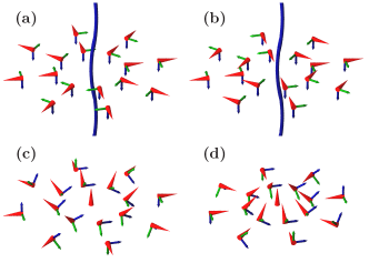
From other vortices in the same equivalence class can be formed by local spin rotations. For example, we may rotate the spin vector such that at each point it points radially away from the vortex line, as illustrated in Fig. 1(a). This vortex corresponds to the choices , and in Eq. (9), and is described by
| (11) |
This singular spin vortex Ho (1998); Ohmi and Machida (1998) illustrates another important aspect of the FM phase: circulation alone is not quantized. The superfluid velocity in the FM phase Ho (1998),
| (12) |
vanishes when and . Therefore the circulation is in fact zero in , but it does carry a nonvanishing spin current around a singularity of the FM spin vector, whose structure is similar to an analogous vortex with a radial disgyration of the angular momentum vector in 3He. Further local spin rotations yield other singular vortices with different spin structures, such as the cross disgyration shown in Fig. 1(b) or a tangential disgyration with .
A striking manifestation of the nonquantization of circulation in the FM phase is the formation of a nonsingular coreless vortex. This can be constructed as a combined rotation of the spin vector and the condensate phase [Fig. 1(c)]: , yielding the spinor
| (13) |
where the Euler angle is now a function of the radial distance , such that as , keeping the spin texture continuous. The superfluid velocity, Eq. (12), becomes
| (14) |
and increases smoothly from zero at as increases away from the vortex, the spin vector forming a fountain-like texture. The coreless vortex in the FM phase of a spin-1 BEC is analogous to the Anderson-Toulouse and Mermin-Ho vortices in superfluid 3He Anderson and Toulouse (1977); Mermin and Ho (1976), which differ by the boundary condition imposed on the angular momentum vector at the container wall. In the BEC there is no hard container wall, and the amount by which turns from the vortex line to the edge of the cloud is determined by the rotation of the trap, causing the total angular momentum to vary smoothly with rotation.
The coreless vortex can be continuously transformed into other members of the class of nonsingular vortices, including the vortex-free state, by purely local operations. The continuous deformation is a striking consequence of the two-element character of the fundamental group of the order-parameter space: the doubly quantized vortex belongs to the same topological class as the nonsingular vortices and the vortex-free state, and can be continuously unwound, if the orientation of the spin texture is not fixed outside the structure. Another nontrivial nonsingular vortex with continuous spin textures is displayed in Fig. 1(d).
We have now identified two topologically distinct classes of vortices that can both carry mass and spin circulation in the FM spin-1 BEC. A similar situation applies in the phase of 3He. There the singular vortex has the lower energy, but the energy barrier for nucleation is lower for the nonsingular vortex Parts et al. (1995). In a rotating FM spin-1 BEC, the coreless vortex has the lower energy and the lower nucleation barrier, and consequently the ground state is made up of nonsingular coreless vortices for sufficiently rapid rotation Mizushima et al. (2002b); Martikainen et al. (2002); Reijnders et al. (2004); Mueller (2004); Takahashi et al. (2009). However, it is also possible to form a singly quantized, singular vortex Isoshima and Machida (2002); Mizushima et al. (2002a), which despite not being the lowest-energy state at any frequency of rotation can nevertheless be energetically stable as a local energy minimum Lovegrove et al. (2012).
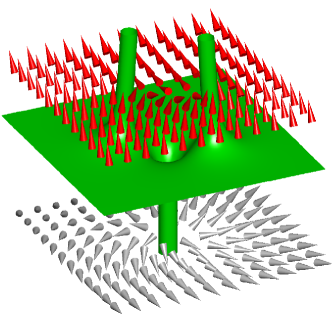
So far we have considered line defects, classified by the first homotopy group . Point defects—monopoles—are analogously classified by the second homotopy group . For the FM order-parameter manifold, the second homotopy group is the trivial group, , indicating that the FM phase does not strictly speaking support point defects. However, it is possible to form a spinor with a monopole structure of the spin vector (a radial hedgehog) as the termination of a doubly quantized vortex Savage and Ruostekoski (2003b) (Fig. 2). This is the analogue of the Dirac monopole in quantum field theory, and the doubly quantized vortex line is called the Dirac string. The corresponding spinor is written by choosing and (where and are the polar and azimuthal angles, respectively) to form
| (15) |
This Dirac monopole can be continuously deformed into the spin structure of the coreless vortex Savage and Ruostekoski (2003b).

II.2.2 Polar phase
We next consider in Eq. (2), in which case the spin-dependent interaction favors a state with . A simple representative polar spinor fulfilling this requirement is . As for the FM phase, the general polar spinor is found by applying a 3D spin rotation together with a condensate phase :
| (16) |
We now make the important observation that the unit vector defines the local direction of macroscopic condensate spin quantization. This allows us to rewrite in terms of this vector as Ruostekoski and Anglin (2003)
| (17) |
The condensate phase , which takes values on a unit circle, and the unit vector , taking values on a sphere, thus together fully specify the order parameter in the polar phase. Note, however, that . These two states must be identified in order to avoid double counting. The order parameter space therefore becomes , where the factorization by the two-element group results from the identification. The vector should thus be taken to be unoriented and defines a nematic axis Zhou (2003), and the order-parameter is correspondingly said to exhibit nematic order, which leads to parallels with the -phase of superfluid 3He.
A simple singly quantized vortex can again be constructed as a winding of the condensate phase, keeping uniform (choosing and to be constants):
| (18) |
In the polar phase the superfluid velocity is Kawaguchi and Ueda (2012)
| (19) |
We observe that depends only on the gradient of the condensate phase, and is independent of . This means that another singly quantized vortex, with the same circulation as that described by Eq. (18), can be formed by allowing to wind by (thus preserving single-valuedness of the order parameter) in addition to the winding of the condensate phase. This is achieved by choosing in Eq. (16), yielding the spinor
| (20) |
One can further show from Eq (19) that circulation is quantized in the polar phase. However, due to the nematic order, the smallest circulation possible is half that of a singly quantized vortex. The equivalence implies that we can allow the condensate phase to wind by along a loop encircling the vortex and still preserve single-valuedness of the the order parameter by a simultaneous winding of the nematic axis Leonhardt and Volovik (2000). If is in the -plane, a half-quantum vortex can be written
| (21) |
In general, the axis about which winds need not coincide with the vortex core. Figure 3(b) shows a half-quantum vortex where winds about an axis perpendicular to the vortex line. This vortex is related to that shown in Fig 3(a) and defined by Eq. (21) by a spin rotation. The resulting spinor wave function may appear quite complicated, but the winding of the nematic axis still allows us to identify the vortex.
Thus circulation is quantized in the polar phase, and indeed one can show that . The topological charges , , etc. are additive. For example, the state with two half-quantum vortices belongs to the same equivalence class as the singly quantized vortices. This observation shall prove important for understanding the core structure of defects that cross a polar-FM interface.
In addition to singular line defects, the polar phase also supports singular point defects Stoof et al. (2001); Ruostekoski and Anglin (2003): A spherically symmetric point defect, analogous to the ’t Hooft-Polyakov monopole in quantum field theory, is formed by choosing in Eq. (16), such that the vector field forms a radial hedgehog structure
| (22) |
Here a singular point defect is located at the origin. The two spinor wave function components form overlapping, singly quantized vortex lines with opposite circulation. The vortex lines are oriented along the axis, normal to a dark soliton plane (phase kink) in the component .
III Topological interface in a spin-1 BEC
The two phases of the spin-1 BEC exhibit different topological properties of the order parameter, which is manifest in the very different defects they support, as detailed in the previous section. We now consider the behavior of the order parameter and defects when the two phases are realized simultaneously in spatially separated regions within the same ultracold gas, so that an interface between the different ground-state manifolds is formed.
The order-parameter manifolds in the FM and polar phases emerge out of the full symmetry of the condensate wave function as the spin-dependent interaction selects an energetically degenerate subset of all possible wave functions. In particular, the order-parameter space in the FM phase consists of all spinor wave functions that maximize the spin magnitude, , everywhere if the texture is uniform. Correspondingly in the polar phase, the order-parameter space is the set of wave functions that have everywhere. These sets are clearly nonoverlapping. However, because they form subsets of the same spin-1 wave function, a continuous connection between spatially separated polar and FM manifolds is possible by exciting the wave function out of its ground-state manifold close to the interface, locally restoring its full symmetry.
In this section we first discuss how the interface may be created in the spinor BEC through local manipulation of the scattering lengths. We then identify the basic interface-crossing defect states and explicitly construct prototype spinor wave functions to describe them. In Sec. IV we minimize the energy of these spinor wave functions for defect configurations and show how this leads to a rich phenomenology of defect structures.
III.1 Creating the topological interface
In order to realize a topological interface in a spinor BEC it is necessary make the system switch continuously between regions of different broken symmetries. Which broken symmetry is preferred in a spin-1 BEC on energetic grounds is determined, as explained in Sec. II.1, by the spin-dependent interaction. Therefore if one can spatially control the interaction strength , Eq. (5), separate FM and polar regions within the same BEC can be engineered. Specifically, since , this implies changing the ratio of the two scattering lengths of colliding spin-1 atoms such that changes sign.
The scattering lengths that determine interaction strengths in ultracold-atom systems are routinely manipulated using magnetic Feshbach resonances. However, this technique cannot be used for our present purpose since the strong magnetic fields required would freeze out the spin degree of freedom and destroy the spinor nature of the BEC. The possibility for engineering the scattering lengths in the spinor BEC is instead provided by the use of either optical Fatemi et al. (2000) or microwave-induced Feshbach resonances Papoular et al. (2010), in which case the fields can be kept sufficiently weak in order not to destroy the spinor nature of the BEC.
We suggest constructing an interface between topologically distinct manifolds in a spinor BEC by local adjustment of the scattering lengths, such that regions with different-sign are created Borgh and Ruostekoski (2012). In a spin-1 BEC experiment, the spatial dependence of the scattering lengths can then result in an interface between coexisting FM and polar phases. Doing so, however, presents practical challenges. If an optical Feshbach resonance is used to manipulate one or both scattering lengths, the spatial pattern corresponding to a sharp interface can be imposed using a holographic mask. Optical Feshbach resonances suffer from inelastic losses Fatemi et al. (2000), but these can be kept small for small adjustments of the scattering lengths. Since the spin-dependent interaction is proportional to the difference between and , only a small relative shift is needed to create the interface if is small, which is true for both 87Rb and 23Na, commonly used in spinor-BEC experiments.
Using a microwave-induced Feshbach resonance avoids the problem of large inelastic losses, but makes engineering the spatial profile more difficult, since, except in specific traps, for example surface microtraps, a microwave field cannot be focused in the same way as the laser. This problem could be overcome by using an optically induced level shift to tune the microwave transition off-resonant. The microwave field could then be applied uniformly across the system, whereas spatial control of the laser field is used to apply the optical tuning only in the region where no shift of is required.
III.2 Construction of prototype interface spinors
The use of optical or microwave-induced Feshbach resonances can thus realize spatially separated polar and FM phases in the same spin-1 BEC, with the condensate wave function remaining continuous, allowing, in principle, defects to connect across the interface. In order to demonstrate the nontrivial nature of defect penetration across the interface between topologically distinct manifolds, we consider a spin-1 BEC where abruptly changes sign at . We choose for and for , such that the interface exists at with the polar phase above it and the FM phase below. In the following, we analytically construct spinor solutions that represent physical wave functions for defects and textures simultaneously in the two different manifolds.
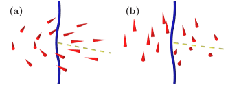
The simplest vortex connection can be identified by considering a singly quantized vortex in both phases, as illustrated schematically in Fig. 4(a). Note that a singly quantized vortex does not mean the same thing in the two phases: the topology that describes vortices is entirely different, one vortex being a product of the broken symmetry manifold SO(3), with the fundamental homotopy group of two elements, and the other one resulting from the broken symmetry , with the fundamental homotopy group of integers that represent the number of half-quanta of circulation. It is therefore not obvious that these different topological objects can be continuously joined across the interface.
In the following we show how to construct spinor wave-function solutions that simultaneously represent a singly quantized vortex line in both phases and perforate through the interface with a winding of the condensate phase around the vortex line (which we take to be along the axis). A similar procedure is then extended to other topological defects and textures. The joining of two singly quantized vortex lines can be achieved by changing the sign of either of the spinor components or . By appropriate choice of parameters doing so causes the spinor wave function to adjust between the two manifolds by forcing to switch from 0 to 1, or else leads to a state which immediately relaxes to the desired configuration. Physically, such a sign-change in one of the two spinor components can be obtained by introducing a dark soliton plane (phase kink) in that component at . The phase shift across the soliton is then associated with a vanishing density in that spinor component at the soliton core. The BEC wave function, however, remains continuous across the interface, since the remaining spinor components have nonvanishing atom densities also at the position of the soliton plane. The BEC wave function thus connects the two manifolds. In this construction, the switch between polar and FM sides is abrupt. In section IV we will see that as energy is relaxed, the interface acquires a finite width determined by the spin healing length , Eq. (7).
Following this procedure and starting from the expression for a singular vortex in the FM phase, Eq. (10), we can write the spinor wave function connecting two singly quantized vortices across the polar-FM interface explicitly as
| (23) |
where the negative sign is used on the polar side of the interface and the positive sign on the FM side. Note that only the choice yields corresponding to an exactly polar state above the interface. However, even for a different the spinor wave function has the appropriate vortex structure and will quickly relax to the polar phase for with a singly quantized vortex. This highlights the general consideration that even though writing exact vortex connections analytically may be very complicated, we have a simple method for finding approximate spinor wave functions representing defect connections.

In Eq. (20) we demonstrated that a singly quantized vortex in the polar phase can include a winding of the nematic axis in addition to the winding of the condensate phase. Comparing Eq. (20) with the solution for a coreless FM vortex in Eq. (13), we note that these have a similar structure in terms of the complex phases of the spinor components. We can therefore construct an approximate wave function representing the connection of a singly quantized vortex in the polar phase with a coreless vortex on the FM side of the interface by the insertion of a soliton plane in in Eq. (20). This yields the interface spinor
| (24) |
where the positive sign is used on the polar side of the interface and the negative sign on the FM side. Choosing or yields on the FM side, and specifically the choice approximates the coreless vortex [Eq. (13)]. This solution relaxes to the characteristic fountain-like spin profile to yield the state illustrated in Fig. 4(b).
In addition to connecting to another vortex across the interface, a vortex could also terminate on a point defect at the interface. Such solutions can be constructed by joining the monopole spinor wave functions of Eqs. (15) and (22) to vortices with analogous phase windings in each of the spinor components. For example, consider the Dirac monopole in the FM phase [Eq. (15)]. By the same construction that resulted in the interface-crossing defect in Eq. (24) we can connect the singular vortex of Eq. (20) on the polar side to the monopole of Eq. (15) at the interface by inserting a soliton plane into . The resulting spinor wave function,
| (25) |
represents the monopole on the FM side of the interface. Here the negative sign refers to the polar side and the positive sign to the FM side. On the polar side the spinor has a structure similar to Eq. (20), thus approximating a singly quantized vortex in the polar phase. The resulting defect configuration is illustrated in Fig. 4(c) and represents a vortex in the polar phase terminating to a monopole at the interface. This defect is closely related to the one shown in Fig. 4(b), as the Dirac monopole and the coreless vortex can be deformed into each other by purely local operations. Note also that in Eq. (25) the Dirac string is represented by the singular polar vortex along the positive axis and there is no line defect on the FM side. By instead aligning the Dirac string with the negative axis, the doubly quantized line defect terminates on the monopole from the FM side, while for positive , the spinor still represents a singular vortex connecting to the monopole from the polar side.
In a similar way a point defect (radial hedgehog) in the polar side [Eq. (22)] can be placed on the interface as the termination point of a singular FM vortex. We consider a defect structure with overlapping, singly quantized vortex lines in , both oriented normal to the interface and of opposite circulation, together with phase kinks in and . This spinor wave function can be parametrized as
| (26) |
using the negative sign on the polar side and the positive sign on the FM side. The resulting structure on the polar side is that of Eq. (22), in which the nematic axis forms a radial hedgehog Stoof et al. (2001); Ruostekoski and Anglin (2003). This represents the polar point defect on the interface. On the FM side the spinor is similar to the singular spin vortex of Eq. (11) with vortex lines of opposite winding in . Hence we have constructed on the FM side an approximation to a spin vortex that terminates to the polar monopole at the interface, as illustrated in Fig. 4(d).
Next we show that vortices can also be made to terminate at the interface. In Eq. (24) and in Fig. 4(b), a singular, singly quantized polar vortex perforates the interface to a coreless FM vortex when a phase kink is inserted in . The resulting defect can be cut in half while still preserving the coherent interface with a continuous order-parameter field by inserting an additional phase kink in . This allows the vortices on different sides of the interface to move apart:
| (27d) | ||||
| (27h) | ||||
where we may choose as in Eq. (24). One possible configuration is illustrated in Fig. 5(a), where the singular polar vortex and a doubly quantized FM vortex are spatially separated and both terminate on the interface.

Since the vortex lines in the individual spinor components terminate on the soliton planes, it is also possible to consider a state where a vortex exists only on one side of the interface, for instance,
| (28d) | ||||
| (28h) | ||||
In addition to singly quantized vortices also half-quantum vortices are possible in the polar phase [Eq. (21)]. A singly quantized vortex can split into two half-quantum vortices while preserving the topology, and such splitting can be energetically favorable Lovegrove et al. (2012). The defect configuration of perforating singly quantized vortices in Fig. 4(a) can therefore also deform to a state in which a singly quantized FM vortex continuously connects to a pair of half-quantum vortices as illustrated in Fig. 5(b). We will demonstrate in the next section that this state does indeed appear as a consequence of energy minimization.
The vortices and monopoles in the spin-1 BEC are made up of vortex lines and soliton planes in the individual spinor components. The construction of the interface-crossing defect solutions was achieved by identifying defects in the two phases that have a similar combination of vortex lines, and using soliton planes to achieve the switch between polar and FM manifolds. Dark solitons have been phase imprinted experimentally Burger et al. (1999); Denschlag et al. (2000). Phase imprinting of vortex lines in a BEC by transferring angular momentum from an electromagnetic field has been proposed theoretically Marzlin et al. (1997); Bolda and Walls (1998); Williams and Holland (1999); Isoshima et al. (2000); Dutton and Ruostekoski (2004) and several of the techniques have also been realized in experiments Matthews et al. (1999); Leanhardt et al. (2002); Shin et al. (2004); Andersen et al. (2006). In spinor BECs, coreless vortices and related textures have been prepared by adiabatic ramping of a magnetic field along the trap axis Leanhardt et al. (2003); Choi et al. (2012a, b), or by population transfer using Laguerre-Gaussian laser Leslie et al. (2009). More complicated vortices and textures could be imprinted using proposed techniques for creating vortex rings Ruostekoski and Anglin (2001); Ruostekoski and Dutton (2005).
Other interface defect configurations can be constructed by combining more elementary defect connections. For instance, in the FM phase the Dirac monopole can be turned inside out to form an antimonopole, in which the spins point radially inward. By joining the Dirac strings of a Dirac monopole and an antimonopole, a Dirac dipole can be constructed Savage and Ruostekoski (2003b). In Fig. 5(c), we illustrate a state where such a dipole is placed on the polar-FM interface. The Dirac string forms a doubly quantized vortex line in the FM phase, connecting the two monopoles. Consequently, the Dirac dipole can form the termination points of two oppositely winding singly quantized vortices [see the construction that lead to Eq. (25)].
IV Core structure of interface-crossing defects
IV.1 Core deformation of interface-crossing defect solutions
In the preceding section we constructed the prototype spinor wave functions for the interface-crossing defect solutions connecting defects in the FM and polar phases. We showed that such solutions can be formed by combinations of elementary vortex lines and dark soliton (phase kink) planes that could be experimentally prepared by phase imprinting. Here we use the constructed spinor wave functions for the defect configurations as initial states for numerical studies of the defect stability. Provided that prototype spinors sufficiently closely approximate the local energetic minimum configuration, the initial states quickly relax to the targeted defect structure.
By numerical simulations we can determine the energetically preferred core structures and the energetic stability of the defects. In order to do so we minimize the free energy in the rotating frame [Eq. (4)] by propagating the coupled Gross-Pitaevskii equations, derived from Eq. (2), in imaginary time using a split-step algorithm Javanainen and Ruostekoski (2006). We assume the slightly elongated trap, defined by Eq. (3). The initial state prototype spinor wave functions are given in Sec. III.2. We choose the spin-independent nonlinearity , where is the transverse oscillator length. For 87Rb in a trap with Hz these parameters correspond to atoms. The spin-dependent nonlinearity, , is allowed to vary.
In Ref. Lovegrove et al. (2012) it was demonstrated that the core of a singly quantized vortex in the FM phase of spin-1 BEC deforms by locally rotating the spin vector so that the vortex lines in the individual spinor components in the appropriate basis representation move apart. The singular vortex line then no longer represents a vanishing atom density, but is occupied by atoms with zero spin magnitude as in the polar phase of the spin-1 BEC. The FM vortex line singularity filled by atoms in the polar phase becomes energetically favorable by allowing a larger core size and a correspondingly smaller bending energy. The core deformation can be understood from the energetics associated with the hierarchy of characteristic length scales determined by the interaction strengths: the size of the filled core is determined by the spin healing length , Eq. (7), which is usually larger than the density healing length , Eq. (6), that sets the size of a core with vanishing density.
Similarly, a singly quantized vortex in the polar phase was shown to lower its energy by spontaneously breaking axial symmetry, splitting into a pair of singular half-quantum vortices Lovegrove et al. (2012). This again avoids depleting the atom density in the vortex core: at the location of the singularities , with spins anti-aligning in the two cores. The two vortices form an extended core region where the order parameter is excited out of the polar ground-state manifold. The size of the core region is then enlarged to be on the order of , with a corresponding decrease in bending energy. The overall topology is preserved away from the two singularities. Inside the extended core region, the splitting of the singly quantized vortex locally deforms the nematic field that describes the order parameter [see Eq. (17)], and a disclination plane, where the identification is made, appears between the vortex lines. Thus on a loop encircling only one line singularity, both condensate phase and nematic axis wind by . The splitting of the singly quantized vortex is closely related to the deformation of a point defect into a half-quantum vortex ring Ruostekoski and Anglin (2003). In the 2D cross section of the ring, the diametrically opposite points on the ring correspond to half-quantum vortices with anti-aligned spins in the cores. In Ref. Ji et al. (2008) dynamic nucleation of half-quantum vortices under energy dissipation was studied, demonstrating formation of a square vortex lattice. To get a simple qualitative picture of the interactions between half-quantum vortices one may consider the corresponding problem in a two-component BEC. In a nonrotating uniform system it was argued that the repulsive force between vortices with opposite core polarisations falls off as Eto et al. (2011).
It was demonstrated in Eq. (23) how singly quantized vortices in the FM and polar phases can be connected across the polar-FM interface, despite the fact that these are two topologically different defects. As the energy is minimized, this interface-crossing defect deforms by a mechanism analogous to that described above for the singly quantized vortices in the purely FM and polar BECs. The resulting structure is shown in Fig. 6. On the polar side of the interface, the splitting of the singly quantized vortex into two half-quantum vortices is recognized from the deformation of the nematic field, which shows the characteristic winding around each singularity, and the formation of the disclination plane. The order-parameter is excited out of the ground-state manifold, to reach at the singular lines. The pair of half-quantum vortices connects across the interface to the singly quantized FM vortex. This, in turn, exhibits the local rotation of the spin vector, allowing the core region to fill by mixing FM and polar phases, with on the singularity.
The relaxed interface-crossing vortex structure is thus recognized as that illustrated schematically in Fig. 5(b), and the deformation is understood in terms of the characteristic length scales set by the atom-atom interactions. In the purely polar or FM condensate, the core-deformed, singly quantized vortices are energetically stable Lovegrove et al. (2012). For the parameter values investigated, the configuration in Fig. 6 ultimately decays for very long relaxation times in our simulations.
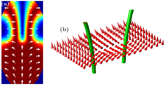
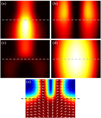
We do, however, find an energetically stable deformation of a singly quantized polar vortex connecting across the interface if instead of starting from of Eq (23), we minimize the energy of from Eq. (24). This spinor describes a singly quantized polar vortex connecting across the interface to a coreless vortex. [A topologically equivalent configuration can be constructed by allowing the polar vortex to terminate on a Dirac monopole, Eq. (25).] Minimizing the energy leads to the deformation shown in Fig. 7. On the FM side of the interface, the spin structure acquires the fountain-like structure characteristic of the coreless vortex, as shown by the white arrows in Fig. 7(a). Here the frequency of rotation determines the direction of the spin vector at the edge of the cloud as the angular momentum in the FM phase adapts to the imposed rotation.
On the polar side of the interface we recognize the splitting of the singly quantized vortex into a pair of half-quantum vortices, identified by the winding of the nematic axis around each vortex [Fig. 7(b)], preserving the overall topology. As before, in the core region the order parameter is excited out of the ground-state manifold, with on the singular lines. Fig. 7(a) shows how the spin texture connects smoothly across the interface.
The continuity of the relaxed spinor wave function is further demonstrated in Fig. 8, giving a detailed picture of the interface region. In the relaxed state, the total atom density remains nonvanishing at the interface and varies smoothly across it. The populations of the individual spinor components are also continuous across the interface. The continuity of the defect-carrying spinor wave function as it crosses between the different broken symmetries means that it represents a continuous connection of defects across the interface. In Fig 8, the position where changes sign is indicated by a dashed line, and shown in panel (e) shows the finite width of the interface region after energy relaxation.
The vortex core structures are particularly intriguing and complex when a vortex terminates to a point defect on the interface. We study a singular FM vortex terminating to a radial hedgehog at the interface ( forms a hemispherical hedgehog on the polar side), as depicted schematically in Fig. 4(d). Unlike the FM Dirac monopole, the polar monopole cannot unwind into simpler vortex configuration. Therefore, while the connection depicted in Fig. 4(b) is equivalent to Fig. 4(c) and leads to the same energy-minimizing defect configuration, Fig. 4(d) is topologically distinct from all other vortex connections.
A constructed prototype spinor wave function representing a singular FM vortex terminating to a hedgehog point defect is given by Eq. (26). At the point defect singularity the atom density is zero. The density depletion at the defect core is energetically costly, and if , Eq. (7), is sufficiently large in comparison with , Eq. (6), the energy cost can be reduced by deforming the point defect into a semi-circular line defect whose ends attach to the interface. The resulting arch-like defect is shown in Fig. 9 together with the spin structure in the FM core (a) and the nematic axis away from the defect on the polar side of the interface (b). The deformation of the defect, schematically illustrated in Fig. 10, is local and the topological charge of the monopole is retained: away from the defect, the radial hedgehog structure of is preserved. This implies that on any closed loop through the arch, must turn by . Consequently, single-valuedness of the spinor wave function requires the condensate phase to also turn by , and we infer that the arch-shaped line defect is a half-quantum vortex. This Alice arch resembles the upper hemispheric part of the Alice ring—a closed half-quantum vortex ring that exhibits the topological charge of a point defect over any surface enclosing the defect Ruostekoski and Anglin (2003). Alice rings also appear in high energy physics Schwarz (1982) with a topological charge similar to the magnetic “Cheshire” charge Alford et al. (1991).


The deformation of the point defect at the interface to an Alice arch results from a complex interplay between the energetic considerations, topology, and the length scale hierarchy in the system. The two characteristic healing lengths determine whether the energy cost of forming the extended vortex core region, where the singularity is occupied by the atoms in the FM phase, offsets the energy cost of the density depletion at a point defect (with a vanishing density at the singularity). We find an abrupt transition point to an Alice arch when . For larger values of the point defect at the interface is preferred to the arch defect. The sharp threshold for the deformation can be understood by the topology. For the point defect there cannot be a singular point with and a spherically symmetric core region with . The nematic axis forms a radial hedgehog structure and this would then imply that the spin vector (always orthogonal to ) would have to form a continuous tangent vector field for the spherically symmetric object which is not possible (“hairy ball” theorem). Therefore the point defect has to deform to a ring or an arch-shaped defect at the interface before the transition from the zero-density singularity to the singularity with nonvanishing density is possible. The sharp deformation threshold also appears in the stability analysis of a singular point defect and the Alice ring Ruostekoski and Anglin (2003)
We note that the arch defect is unstable towards drifting out of the cloud due to the density gradient resulting from the harmonic trapping potential. It could potentially be stabilized using a weak pinning laser to create a small density depletion at the center of the trap.
The structure of the arch defect emerging from the point defect may be understood by studying the individual spinor wave function components. In the point defect with vanishing density at the singularity, the overlapping vortex lines in intersect with the soliton plane in . In the prototype spinor wave function an additional soliton plane is present in to account for the switch from the polar to the FM side of the interface. In Ref. Ruostekoski and Anglin (2003) the deformation of the spherically symmetric point defect was explained by a local separation of the vortex lines in such that they no longer overlap at the soliton plane. Here the additional soliton plane in cuts the vortex line in at the interface, separating the two parts. The spinor components are shown in Fig. 9(c). The positions of the Alice arch and the FM vortex are indicated, and we find how in the polar part of the cloud, the separated vortex lines make up the semi-circular half-quantum vortex. On the FM side, the unbroken vortex line in and the part of the vortex line in form the spinor wave function of the FM vortex whose core is filled by the vortex-free component.
At high rotation frequencies of the trap, we find nucleation of interface-crossing defects in the energy minimization. Provided that the appropriate instability for nucleating vortices is triggered, the emergence of defect configurations where a half-quantum vortex connects to a coreless vortex spontaneously emerges, as they lower the energy of the system in a sufficiently rapidly rotating trap. An example is shown in Fig. 11, in which four interface-crossing vortices nucleate. On the polar side of the interface, four singular lines appear, on which . These vortices may be identified as half-quantum vortices through the winding of the nematic axis. On the FM side, the order parameter remains nonsingular. However, the spin texture reveals that each of the four half-quantum vortices connects to a coreless vortex.

V Conclusions
Interfaces between topologically distinct ground-state manifolds play an important role in several areas of physics, many of which are difficult or impossible to access experimentally. Here we have given a detailed analysis of our proposal for how topological interface physics of defects and textures can be studied in ultracold atomic gases Borgh and Ruostekoski (2012). We considered the specific example of a spin-1 BEC with spatially separated polar and FM regions within a continuous condensate wave function. For a number of representative, interface-crossing defect states, we provided detailed constructions of prototype spinor wave functions by considering how basic vortex and monopole solutions with similar spinor structure represent different topological objects in the two phases. The resulting wave functions are built from vortex lines and soliton planes in the individual spinor components that could be phase-imprinted using existing experimental techniques Matthews et al. (1999); Leanhardt et al. (2002); Shin et al. (2004); Andersen et al. (2006); Ruostekoski and Anglin (2001); Ruostekoski and Dutton (2005); Burger et al. (1999); Denschlag et al. (2000).
The energetic stability and energy-minimizing core structures of the interface-crossing defect configurations were analyzed by numerically minimizing the energy of the prototype wave functions. The resulting spinor states demonstrate how the condensate wave function smoothly interpolates between the two ground-state manifolds by locally restoring its full symmetry, thereby establishing a coherent interface through which defects may connect continuously. In particular, we demonstrated the energetically stable connection of a coreless vortex to a pair of half-quantum vortices, and the formation of an Alice arch: the deformation of a point defect at the interface into an arch-shaped half-quantum vortex line that preserves the topological charge.
In order to demonstrate the basic principle of the topological interface physics in ultracold atoms, we have concentrated in this work on a relatively simple and accessible example of defect perforation across constructed interfaces in spin-1 BECs. The interface analysis, however, can also be applied to more complex systems, such as spin-2 Koashi and Ueda (2000); Ciobanu et al. (2000); Semenoff and Zhou (2007) and spin-3 Barnett et al. (2006); Santos and Pfau (2006) BECs, where, for example, non-Abelian defects are predicted Kobayashi et al. (2009); Huhtamäki et al. (2009). Other particularly promising platforms for topological interface studies are strongly correlated atoms in optical lattices Greiner et al. (2002); Jördens et al. (2008); Schneider et al. (2008) exhibiting also quantum phase transitions and potential analogues of exotic superconductivity Bert et al. (2011) in crystal lattices.
Moreover, the interface scheme may be used to investigate nonequilibrium dynamical scenarios for production of topological defects and textures in phase transitions. An intriguing possibility is production of topological defects in experiments inspired by brane-inflation models, where brane annihilation leads to formation of defects Dvali and Tye (1999); Sarangi and Tye (2002). In a FM BEC, a region of polar phase can be created by locally shifting the spin-dependent interaction strength. The resulting phase boundaries then form two-dimensional analogues of -branes. When the interaction shift is removed, the polar region collapses, simulating brane-antibrane annihilation, and resulting defects can be observed in the cloud. This is similar to a recent experiment in 3He Bradley et al. (2008), where, however the defects are more difficult to observe directly.
Defect production may also result from dynamic instabilities, for example arising from superfluid counterflow between the FM and polar phases. The boundary between two fluids moving with respect to each other becomes unstable if the relative velocity exceeds some critical value, leading to excitations on the interface. This phenomenon is well understood in classical fluid mechanics and is known as the Kelvin-Helmholtz instability Kundu and Cohen (2008). An analogous superfluid Kelvin-Helmholtz instability has been shown to occur at the interface between superfluid 3He and , providing another active area of research related to interfaces between different ordered phases Finne et al. (2006). Vortices in the phase cause counterflow against the initially vortex-free phase. As the relative velocity exceeds a critical value, vortices nucleate from the interface into the phase. A superfluid Kelvin-Helmholtz instability has also been predicted in phase-separated two-component BECs Suzuki et al. (2010); Lundh and Martikainen (2012).
Acknowledgements.
We thank D. J. Papoular for enlightening discussions. Financial support from the Leverhulme trust is gratefully acknowledged.References
- Mermin (1979) N. D. Mermin, Rev. Mod. Phys. 51, 591 (1979).
- Vollhardt and Wölfle (1990) D. Vollhardt and P. Wölfle, The Superfluid Phases of Helium 3 (Taylor & Francis Ltd, London, UK, 1990).
- Stenger et al. (1998) J. Stenger, S. Inouye, D. M. Stamper-Kurn, H. Miesner, A. P. Chikkatur, and W. Ketterle, Nature 396, 345 (1998).
- Kawaguchi and Ueda (2012) Y. Kawaguchi and M. Ueda, Phys. Rep. 520, 253 (2012).
- Stamper-Kurn and Ueda (2012) D. M. Stamper-Kurn and M. Ueda, arXiv:1205.1888 (2012).
- Kibble (1976) T. W. B. Kibble, J. Phys. A: Mat. Gen. 9, 1387 (1976).
- Vilenkin and Shellard (1994) A. Vilenkin and E. P. S. Shellard, Cosmic Strings and Other Topological Defects (Cambridge University Press, 1994).
- Dvali and Tye (1999) G. Dvali and S.-H. H. Tye, Phys. Lett. B 450, 72 (1999).
- Sarangi and Tye (2002) S. Sarangi and S.-H. H. Tye, Phys. Lett. B 536, 185 (2002).
- Bert et al. (2011) J. A. Bert, B. Kalisky, C. Bell, M. Kim, Y. Hikita, H. Y. Hwang, and K. A. Moler, Nat. Phys. 7, 767 (2011).
- Salomaa (1987) M. M. Salomaa, Nature 326, 367 (1987).
- Volovik (2003) G. E. Volovik, The Universe in a Helium Droplet (Oxford University Press, 2003).
- Finne et al. (2006) A. P. Finne, V. B. Eltsov, R. Hänninen, N. B. Kopnin, J. Kopu, M. Krusius, M. Tsubota, and G. E. Volovik, Rep. Prog. Phys. 69, 3157 (2006).
- Bradley et al. (2008) D. I. Bradley, S. N. Fisher, A. M. Guenault, R. P. Haley, J. Kopu, H. Martin, G. R. Pickett, J. E. Roberts, and V. Tsepelin, Nat. Phys. 4, 46 (2008).
- Zurek (1985) W. H. Zurek, Nature 317, 505 (1985).
- Bäuerle et al. (1996) C. Bäuerle, Y. M. Bunkov, S. N. Fisher, H. Godfrin, and G. R. Pickett, Nature 382, 332 (1996).
- Ruutu et al. (1996) V. M. H. Ruutu, V. B. Eltsov, A. J. Gill, T. W. B. Kibble, M. Krusius, Y. G. Makhlin, B. Plaçais, G. E. Volovik, and W. Xu, Nature 382, 334 (1996).
- Weiler et al. (2008) C. N. Weiler, T. W. Neely, D. R. Scherer, A. S. Bradley, M. J. Davis, and B. P. Anderson, Nature 455, 948 (2008).
- Nitta et al. (2012) M. Nitta, K. Kasamatsu, M. Tsubota, and H. Takeuchi, Phys. Rev. A 85, 053639 (2012).
- Battye et al. (2002) R. A. Battye, N. R. Cooper, and P. M. Sutcliffe, Phys. Rev. Lett. 88, 080401 (2002).
- Savage and Ruostekoski (2003a) C. M. Savage and J. Ruostekoski, Phys. Rev. Lett. 91, 010403 (2003a).
- Ruostekoski (2004) J. Ruostekoski, Phys. Rev. A 70, 041601 (2004).
- Borgh and Ruostekoski (2012) M. O. Borgh and J. Ruostekoski, Phys. Rev. Lett. 109, 015302 (2012).
- Ho (1998) T.-L. Ho, Phys. Rev. Lett. 81, 742 (1998).
- Ohmi and Machida (1998) T. Ohmi and K. Machida, J. Phys. Soc. Jpn 67, 1822 (1998).
- Zhou (2003) F. Zhou, Int. J. Mod. Phys. B 17, 2643 (2003).
- Koashi and Ueda (2000) M. Koashi and M. Ueda, Phys. Rev. Lett. 84, 1066 (2000).
- Ciobanu et al. (2000) C. V. Ciobanu, S.-K. Yip, and T.-L. Ho, Phys. Rev. A 61, 033607 (2000).
- Barnett et al. (2006) R. Barnett, A. Turner, and E. Demler, Phys. Rev. Lett. 97, 180412 (2006).
- Santos and Pfau (2006) L. Santos and T. Pfau, Phys. Rev. Lett. 96, 190404 (2006).
- Salomaa and Volovik (1987) M. M. Salomaa and G. E. Volovik, Rev. Mod. Phys. 59, 533 (1987).
- Manton and Sutcliffe (2004) N. Manton and P. Sutcliffe, Topological Solitons (Cambridge University Press, 2004).
- Bogomolny (1976) E. B. Bogomolny, Sov. J. Nucl. Phys 24, 449 (1976).
- Jackiw and Rebbi (1976) R. Jackiw and C. Rebbi, Phys. Rev. D 13, 3398 (1976).
- Faddeev and Niemi (1997) L. Faddeev and A. J. Niemi, Nature 387, 58 (1997).
- Busch and Anglin (2001) T. Busch and J. R. Anglin, Phys. Rev. Lett. 87, 010401 (2001).
- Öhberg and Santos (2001) P. Öhberg and L. Santos, Phys. Rev. Lett. 86, 2918 (2001).
- Kevrekidis et al. (2004) P. Kevrekidis, H. Nistazakis, D. Frantzeskakis, B. Malomed, and R. Carretero-González, Eur. Phys. J. D 28, 181 (2004).
- Berloff (2005) N. G. Berloff, Phys. Rev. Lett. 94, 120401 (2005).
- Shrestha et al. (2009) U. Shrestha, J. Javanainen, and J. Ruostekoski, Phys. Rev. Lett. 103, 190401 (2009).
- Yin et al. (2011) C. Yin, N. G. Berloff, V. M. Pérez-García, D. Novoa, A. V. Carpentier, and H. Michinel, Phys. Rev. A 83, 051605 (2011).
- Nistazakis et al. (2008) H. E. Nistazakis, D. J. Frantzeskakis, P. G. Kevrekidis, B. A. Malomed, and R. Carretero-González, Phys. Rev. A 77, 033612 (2008).
- Carretero-González et al. (2008) R. Carretero-González, D. J. Frantzeskakis, and P. G. Kevrekidis, Nonlinearity 21, R139 (2008).
- Kasamatsu et al. (2003) K. Kasamatsu, M. Tsubota, and M. Ueda, Phys. Rev. Lett. 91, 150406 (2003).
- Ruostekoski and Anglin (2001) J. Ruostekoski and J. R. Anglin, Phys. Rev. Lett. 86, 3934 (2001).
- Al Khawaja and Stoof (2001) U. Al Khawaja and H. Stoof, Nature 411, 918 (2001).
- Kawakami et al. (2012) T. Kawakami, T. Mizushima, M. Nitta, and K. Machida, Phys. Rev. Lett. 109, 015301 (2012).
- Yip (1999) S.-K. Yip, Phys. Rev. Lett. 83, 4677 (1999).
- Leonhardt and Volovik (2000) U. Leonhardt and G. Volovik, JETP Lett. 72, 46 (2000).
- Stoof et al. (2001) H. T. C. Stoof, E. Vliegen, and U. Al Khawaja, Phys. Rev. Lett. 87, 120407 (2001).
- Isoshima and Machida (2002) T. Isoshima and K. Machida, Phys. Rev. A 66, 023602 (2002).
- Mizushima et al. (2002a) T. Mizushima, K. Machida, and T. Kita, Phys. Rev. A 66, 053610 (2002a).
- Mizushima et al. (2002b) T. Mizushima, K. Machida, and T. Kita, Phys. Rev. Lett. 89, 030401 (2002b).
- Martikainen et al. (2002) J.-P. Martikainen, A. Collin, and K.-A. Suominen, Phys. Rev. A 66, 053604 (2002).
- Ruostekoski and Anglin (2003) J. Ruostekoski and J. R. Anglin, Phys. Rev. Lett. 91, 190402 (2003).
- Savage and Ruostekoski (2003b) C. M. Savage and J. Ruostekoski, Phys. Rev. A 68, 043604 (2003b).
- Reijnders et al. (2004) J. W. Reijnders, F. J. M. van Lankvelt, K. Schoutens, and N. Read, Phys. Rev. A 69, 023612 (2004).
- Mueller (2004) E. J. Mueller, Phys. Rev. A 69, 033606 (2004).
- Saito et al. (2006) H. Saito, Y. Kawaguchi, and M. Ueda, Phys. Rev. Lett. 96, 065302 (2006).
- Ji et al. (2008) A.-C. Ji, W. M. Liu, J. L. Song, and F. Zhou, Phys. Rev. Lett. 101, 010402 (2008).
- Takahashi et al. (2009) M. Takahashi, V. Pietilä, M. Möttönen, T. Mizushima, and K. Machida, Phys. Rev. A 79, 023618 (2009).
- Simula et al. (2011) T. P. Simula, J. A. M. Huhtamäki, M. Takahashi, T. Mizushima, and K. Machida, J. Phys. Soc. Jpn 80, 013001 (2011).
- Lovegrove et al. (2012) J. Lovegrove, M. O. Borgh, and J. Ruostekoski, Phys. Rev. A 86, 013613 (2012).
- Semenoff and Zhou (2007) G. W. Semenoff and F. Zhou, Phys. Rev. Lett. 98, 100401 (2007).
- Huhtamäki et al. (2009) J. A. M. Huhtamäki, T. P. Simula, M. Kobayashi, and K. Machida, Phys. Rev. A 80, 051601 (2009).
- Kobayashi et al. (2009) M. Kobayashi, Y. Kawaguchi, M. Nitta, and M. Ueda, Phys. Rev. Lett. 103, 115301 (2009).
- Barnett et al. (2007) R. Barnett, A. Turner, and E. Demler, Phys. Rev. A 76, 013605 (2007).
- Takeuchi and Tsubota (2006) H. Takeuchi and M. Tsubota, J. Phys. Soc. Jpn 75, 063601 (2006).
- Kasamatsu et al. (2010) K. Kasamatsu, H. Takeuchi, M. Nitta, and M. Tsubota, J. High Energy Phys. 011, 068 (2010).
- Leanhardt et al. (2003) A. E. Leanhardt, Y. Shin, D. Kielpinski, D. E. Pritchard, and W. Ketterle, Phys. Rev. Lett. 90, 140403 (2003).
- Leslie et al. (2009) L. S. Leslie, A. Hansen, K. C. Wright, B. M. Deutsch, and N. P. Bigelow, Phys. Rev. Lett. 103, 250401 (2009).
- Choi et al. (2012a) J.-y. Choi, W. J. Kwon, and Y.-i. Shin, Phys. Rev. Lett. 108, 035301 (2012a).
- Choi et al. (2012b) J.-y. Choi, W. J. Kwon, M. Lee, H. Jeong, K. An, and Y.-i. Shin, New J. Phys. 14, 053013 (2012b).
- Sadler et al. (2006) L. E. Sadler, J. M. Higbie, S. R. Leslie, M. Vengalattore, and D. M. Stamper-Kurn, Nature 443, 312 (2006).
- Vengalattore et al. (2008) M. Vengalattore, S. R. Leslie, J. Guzman, and D. M. Stamper-Kurn, Phys. Rev. Lett. 100, 170403 (2008).
- Kronjäger et al. (2010) J. Kronjäger, C. Becker, P. Soltan-Panahi, K. Bongs, and K. Sengstock, Phys. Rev. Lett. 105, 090402 (2010).
- Bookjans et al. (2011) E. M. Bookjans, A. Vinit, and C. Raman, Phys. Rev. Lett. 107, 195306 (2011).
- Dalibard et al. (2011) J. Dalibard, F. Gerbier, G. Juzeliūnas, and P. Öhberg, Rev. Mod. Phys. 83, 1523 (2011).
- Lin et al. (2009) Y.-J. Lin, R. L. Compton, K. Jiménez-García, J. V. Porto, and I. B. Spielman, Nature 462, 628 (2009).
- Lin et al. (2011) Y.-J. Lin, K. Jiménez-García, and I. B. Spielman, Nature 471, 83 (2011).
- Pethick and Smith (2002) C. Pethick and H. Smith, Bose-Einstein Condensation in Dilute Gases (Cambridge University Press, 2002).
- (82) J. Lovegrove, M. O. Borgh, and J. Ruostekoski, under preparation .
- van Kempen et al. (2002) E. G. M. van Kempen, S. J. J. M. F. Kokkelmans, D. J. Heinzen, and B. J. Verhaar, Phys. Rev. Lett. 88, 093201 (2002).
- Crubellier et al. (1999) A. Crubellier, O. Dulieu, F. Masnou-Seeuws, M. Elbs, H. Knöckel, and E. Tiemann, Eur. Phys. J. D 6, 211 (1999).
- Anderson and Toulouse (1977) P. W. Anderson and G. Toulouse, Phys. Rev. Lett. 38, 508 (1977).
- Mermin and Ho (1976) N. D. Mermin and T.-L. Ho, Phys. Rev. Lett. 36, 594 (1976).
- Parts et al. (1995) Ü. Parts, J. M. Karimäki, J. H. Koivuniemi, M. Krusius, V. M. H. Ruutu, E. V. Thuneberg, and G. E. Volovik, Phys. Rev. Lett. 75, 3320 (1995).
- Fatemi et al. (2000) F. K. Fatemi, K. M. Jones, and P. D. Lett, Phys. Rev. Lett. 85, 4462 (2000).
- Papoular et al. (2010) D. J. Papoular, G. V. Shlyapnikov, and J. Dalibard, Phys. Rev. A 81, 041603 (2010).
- Burger et al. (1999) S. Burger, K. Bongs, S. Dettmer, W. Ertmer, K. Sengstock, A. Sanpera, G. V. Shlyapnikov, and M. Lewenstein, Phys. Rev. Lett. 83, 5198 (1999).
- Denschlag et al. (2000) J. Denschlag, J. E. Simsarian, D. L. Feder, C. W. Clark, L. A. Collins, J. Cubizolles, L. Deng, E. W. Hagley, K. Helmerson, W. P. Reinhardt, S. L. Rolston, B. I. Schneider, and W. D. Phillips, Science 287, 97 (2000).
- Marzlin et al. (1997) K.-P. Marzlin, W. Zhang, and E. M. Wright, Phys. Rev. Lett. 79, 4728 (1997).
- Bolda and Walls (1998) E. L. Bolda and D. F. Walls, Physics Letters A 246, 32 (1998).
- Williams and Holland (1999) J. E. Williams and M. J. Holland, Nature 401, 568 (1999).
- Isoshima et al. (2000) T. Isoshima, M. Nakahara, T. Ohmi, and K. Machida, Phys. Rev. A 61, 063610 (2000).
- Dutton and Ruostekoski (2004) Z. Dutton and J. Ruostekoski, Phys. Rev. Lett. 93, 193602 (2004).
- Matthews et al. (1999) M. R. Matthews, B. P. Anderson, P. C. Haljan, D. S. Hall, C. E. Wieman, and E. A. Cornell, Phys. Rev. Lett. 83, 2498 (1999).
- Leanhardt et al. (2002) A. E. Leanhardt, A. Görlitz, A. P. Chikkatur, D. Kielpinski, Y. Shin, D. E. Pritchard, and W. Ketterle, Phys. Rev. Lett. 89, 190403 (2002).
- Shin et al. (2004) Y. Shin, M. Saba, M. Vengalattore, T. A. Pasquini, C. Sanner, A. E. Leanhardt, M. Prentiss, D. E. Pritchard, and W. Ketterle, Phys. Rev. Lett. 93, 160406 (2004).
- Andersen et al. (2006) M. F. Andersen, C. Ryu, P. Cladé, V. Natarajan, A. Vaziri, K. Helmerson, and W. D. Phillips, Phys. Rev. Lett. 97, 170406 (2006).
- Ruostekoski and Dutton (2005) J. Ruostekoski and Z. Dutton, Phys. Rev. A 72, 063626 (2005).
- Javanainen and Ruostekoski (2006) J. Javanainen and J. Ruostekoski, J. Phys. A Mat. Gen. 39, L179 (2006).
- Eto et al. (2011) M. Eto, K. Kasamatsu, M. Nitta, H. Takeuchi, and M. Tsubota, Phys. Rev. A 83, 063603 (2011).
- Schwarz (1982) A. S. Schwarz, Nucl. Phys. B 208, 141 (1982).
- Alford et al. (1991) M. Alford, K. Benson, S. Coleman, J. Marchrussel, and F. Wilczek, Nucl. Phys. B 349, 414 (1991).
- Greiner et al. (2002) M. Greiner, O. Mandel, T. Esslinger, T. W. Hänsch, and I. Bloch, Nature 415, 39 (2002).
- Jördens et al. (2008) R. Jördens, N. Strohmaier, K. Günter, H. Moritz, and T. Esslinger, Nature 455, 204 (2008).
- Schneider et al. (2008) U. Schneider, L. Hackermüller, S. Will, T. Best, I. Bloch, T. A. Costi, R. W. Helmes, D. Rasch, and A. Rosch, Science 322, 1520 (2008).
- Kundu and Cohen (2008) P. K. Kundu and I. M. Cohen, Fluid Mechanics, 4th ed. (Academic Press, New York, 2008).
- Suzuki et al. (2010) N. Suzuki, H. Takeuchi, K. Kasamatsu, M. Tsubota, and H. Saito, Phys. Rev. A 82, 063604 (2010).
- Lundh and Martikainen (2012) E. Lundh and J.-P. Martikainen, Phys. Rev. A 85, 023628 (2012).