The Polarized H and D Atomic Beam Source for ANKE at COSY-Jülich
Abstract
A polarized atomic beam source was developed for the polarized internal storage-cell gas target at the magnet spectrometer ANKE of COSY-Jülich. The intensities of the beams injected into the storage cell, measured with a compression tube, are hydrogen atoms/s (two hyperfine states) and deuterium atoms/s (three hyperfine states). For the hydrogen beam the achieved vector polarizations are . For the deuterium beam, the obtained combinations of vector and tensor () polarizations are (with a constant ), and or (both with vanishing ). The paper includes a detailed technical description of the apparatus and of the investigations performed during the development.
pacs:
29.25.Pj, 24.70.+sI Introduction
Single-polarized experiments, making use of the polarized proton and deuteron beams of the cooler storage ring COSY-Jülich and unpolarized targets, are extended to double-polarized studies COSY152 by the installation of an internal polarized hydrogen or deuterium storage-cell gas target. Utilizing pure gas of polarized hydrogen or deuterium, these targets circumvent the problem of dilution by unpolarized nucleons and they permit fast change of the polarization direction. In order to compensate for the relatively low areal density, these targets are placed inside storage rings, where they are traversed by the orbiting beam typically a million times per second. As conceived already some forty years ago Haeberli_1965 , a substantial enhancement of the areal target-gas density (or luminosity) compared to gas-jet targets by about two orders of magnitude is achieved, when the polarized atoms are injected into an open-ended, T-shaped storage cell. A review describing the capabilities of polarized gas-jet and storage-cell gas targets is found in Ref. Steffens+Haeberli_2003 .
The polarized internal target (PIT), developed for the magnet spectrometer ANKE Barsov_et_al_2001 in COSY Jülich Maier_1997 , consists of the polarized atomic beam source (ABS), the storage cell KG_2012 , and the Lamb-shift polarimeter (LSP) Engels_et_al_2003 ; Engels_et_al_2005_1 . In the development of the PIT for ANKE the experience of other groups in the operation of polarized gas targets could be used. Essentially these are the Madison source Wise_et_al_1993 , used by the PINTEX collaboration at IUCF Dezarn_et_al_1995 ; Rinckel et al 2000 , and the FILTEX source Stock_et_al_1994 used by the HERMES collaboration at DESY/Hamburg Nass_et_al_2003 .
Section II presents the general layout of the ABS and it describes the major elements, the pumping system, the layout of the baffles, the dissociator, the nozzle-skimmer setup, the system of sextupole magnets, the high-frequency transition units, and the slow control system. Section III contains studies with the free hydrogen jet from the nozzle. In Secs. IV to VII measurements and results are presented concerning the properties of the beam behind the last magnet, the hydrogen and deuterium beam intensities (IV), hydrogen beam profiles (V), the degree of dissociation of the hydrogen beam (VI), and the polarization values for the hydrogen and deuterium beam (VII). Finally, in Sec. VIII, the conclusions and an outlook to the future efforts are given. The procedure of discharge-tube and nozzle conditioning is described in Appendix A.
II Description of the Setup
II.1 General layout of the ABS
The limited space at the target position between the first beam-bending dipole magnet D1 and the central spectrometer dipole magnet D2 of the ANKE facility Barsov_et_al_2001 on the one hand enforces the ABS to be mounted in a vertical position contrary to the layout of the earlier sources. On the other hand, this position allows less complicated supports of the components and easier alignment. Furthermore, the height of the COSY tunnel restricts the vertical dimension of the ABS, which requires a very compact layout of the source. Initially, a slight inclination from the vertical ABS orientation had been foreseen to avoid drizzling of powder, created during operation of the dissociator, down into the storage cell. Production of such a powder had been observed earlier ( Derenchuk_et_al_1994 ; Okamura_et_al_1994 , ”green powder” Hatanaka_et_al_1997 ). No such powder, however, was found on a glass window at the exit of the ABS in vertical position after weeks of dissociator operation. Thus, the inclination could be regarded as unnecessary.
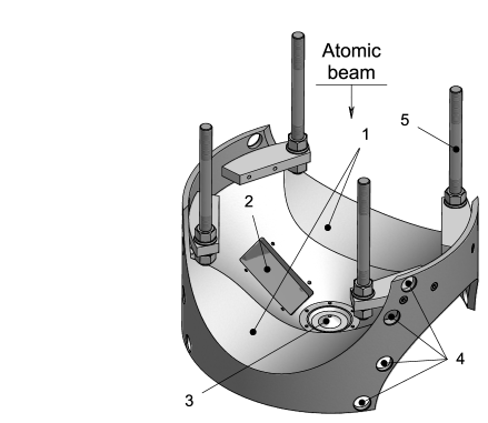
The layout of the ABS is presented in Fig. 1. The two main cylindrical vacuum vessels are fixed above and below a central support plate. The inner diameter of the upper vessel Schiffer is about 390 mm. It houses the chambers I, II, and III, which are separated by two conical baffles. The dissociator tube and the coldhead RGS120 with the heat bridge for nozzle cooling are mounted on a three-legged plate. Three screws allow one to adjust the radial nozzle position and the distance to the skimmer.
The upper baffle between chamber I and II with the beam skimmer is rigidly connected to the upper flange of the vessel. The lower baffle with the diaphragm in front of the first sextupole magnet, separating the chambers II and III, can be moved axially from outside to optimize the pumping conditions on the one hand between the skimmer and the diaphragm, and on the other in the narrow region between the diaphragm and the front face of the first magnet. The first set of three sextupole magnets and the medium field rf transition (MFT) unit in chamber III are carried by two rods attached to the central support plate. The lower vacuum vessel, chamber IV, has a smaller inner diameter of 200 mm. It houses the second set of three sextupole magnets and a cylindrical beam chopper rotating around a horizontal axis. The separate chamber V provides space for the weak and strong field rf transition units (WFT and SFT units, respectively). The ABS can be separated from the ANKE target chamber and the COSY vacuum system by

a gate valve VAT-mini embedded by a dedicated construction into the end flange of chamber V.
Two strong turbomolecular pumps are installed at opposite flanges of chamber I perpendicular to the beam direction, one on the beam-up side of chamber II. The chambers III, IV, and V are evacuated by cryopumps. Due to space limitation around the ABS, shutters on the cryopumps as used in other sources were omitted. The gas originating from regeneration of the cryopumps is pumped via bypass tubes by turbomolecular pumps on the upper chambers. During regeneration as in other cases of pressure increase the gate valve on chamber V is closed to avoid gas flow into the ANKE target chamber.
Details of the pumping system, the baffles, the dissociator, the area around the nozzle, the magnet system, the rf transition units, and the slow control system are described in the subsequent subsections.
II.2 Pumping System
The system of pumps on the chambers I to V of the ABS (Fig. 1) is shown in Fig. 2, the types of the pumps, their pumping speeds, and the achieved pressures are listed in Table 1. Chamber I with the highest gas load, due to the effect of the skimmer, is pumped by two strong turbomolecular pumps. Each of them is backed by a smaller turbomolecular pump.

| Cham- | Device | Type | Pressure | ||
|---|---|---|---|---|---|
| ber | [bar ] | [/s] | [mbar] | ||
| I | TP1-2 | TPH 2200111Pfeiffer Vacuum GmbH, 35614 Asslar, Germany. | 2800 | ||
| TP4-5,7 | TMH 260111Pfeiffer Vacuum GmbH, 35614 Asslar, Germany. | 180 | |||
| MP1-2 | MVP 100-3111Pfeiffer Vacuum GmbH, 35614 Asslar, Germany. | 1.8/1.2333Pumping speed at 1000 mbar/10 mbar | |||
| II | TP3 | TPH 2200111Pfeiffer Vacuum GmbH, 35614 Asslar, Germany. | 2800 | ||
| TP6 | TMH 260111Pfeiffer Vacuum GmbH, 35614 Asslar, Germany. | 180 | |||
| MP3 | MVP 100-3111Pfeiffer Vacuum GmbH, 35614 Asslar, Germany. | 1.8/1.2333Pumping speed at 1000 mbar/10 mbar | |||
| III | CP1 | COOLVAC 3000222Leybold Vakuum GmbH, 50968 Köln, Germany. | 28444At mbar. | 5000 | |
| IV | CP2 | COOLVAC 1500222Leybold Vakuum GmbH, 50968 Köln, Germany. | 28444At mbar. | 5000 | |
| V | CP3 | COOLVAC 800222Leybold Vakuum GmbH, 50968 Köln, Germany. | 4.3444At mbar. | 1000 |
Their exhausts are connected to a common pump of the same type. The total compression ratios of the serially connected turbomolecular pumps yields sufficient pumping speed for a primary molecular gas flow up to 3 mbar /s into the dissociator. The line of pumps is backed by two oil free membrane pumps. According to the lower gas load, chamber II is evacuated by a simpler line consisting of two turbomolecular pumps and a membrane pump. All turbomolecular pumps are operated with use of synthetic oil Fomblin . Compared to mineral oil, synthetic oil allows longer pumping of hydrogen before oil exchange becomes mandatory. Strong cryopumps are utilized on chambers III and IV, while the lowest chamber with the WFT and SFT units is evacuated by a smaller cryopump. All cryopumps are equipped with temperature-controlled heating units for regeneration on both cooling stages HU1 . Heating up to room temperature while pumping the resulting gas load by the bypass system and cooling down again takes about 2.5 to 3 hours.
II.3 Baffles
The layout of the baffles had been defined by the necessary narrow vertical extension of the ABS and the requirement to provide sufficient pumping speed in view of the heavy gas load to the vacuum chambers I and II. Furthermore, the construction aimed at the possibility of axial movements from outside to optimize the beam parameters by variation of the distances between nozzle, skimmer, and diaphragm. The resulting shape for the upper baffle is shown in Fig. 3. Except for details in the openings, the lower baffle, carrying the diaphragm, is identical. The layout of the upper vessel and the baffles was done under the boundary conditions that, on the one hand, the baffles have to be movable within the vessel and, on the other hand, the slits between cylindrical surfaces of the baffles and the inner surface of the vessel has to be narrow to reach a small gas conductance. The diameter of the inner vessel surface is 389.2 mm with a longitudinal and non-circular tolerance of +0.2 mm, the outer diameters of both baffels are (388.7-0.2) mm. The conductances of the slits of 5 /s are small compared with the applied pumping speed. Because of the complicated shape, identical raw pieces of cast Al SKI were machined to the final dimensions.
Contrary to the lower baffle, the upper baffle until now has to be installed together with the flange of the upper vessel at a fixed axial position (cf. Fig. 1). In order to reach full flexibility in varying the nozzle, skimmer, and collimator relative positions from outside, the installation of rotational feedthroughs in the flange of the upper vacuum vessel is necessary, a foreseen but not yet implemented feature.
II.4 Dissociator
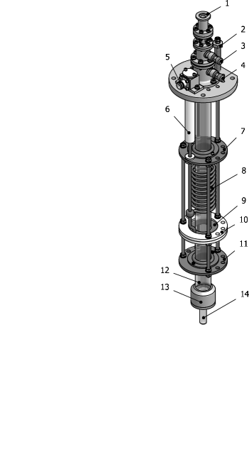
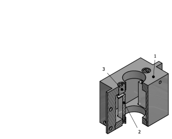
To dissociate molecular hydrogen or deuterium to neutral atoms, an rf discharge is employed which is fed by a 13.560 MHz generator PFG600 delivering up to 600 W into a 50 load. The layout of the dissociator, shown in Fig. 4, is similar to that of the FILTEX design Korsch_Diss_1990 ; Stock_et_al_1996 . The discharge tube () TubeDia is surrounded by two coaxial tubes ( and ), all three are made from borosilicate glass DURAN . The coolant streams from the inlet connection down between the discharge tube and the middle tube and, after flow reversal at the lower end (Fig. 5, label 2) it streams up in the outer slit to the outlet connection. In a closed loop, the coolant inlet temperature (typically 15 ∘C for a 50% water – 50% ethanol mixture) is stabilized by a cooling thermostate LAUDA , which would allow coolant temperatures down to C. The rf coil and the capacitor, at fixed relative positions, can be positioned from outside by means of a sliding rf connection ODU and the feed-through ground connection. This enables variation of the plasma-nozzle distance to optimize the atomic beam intensity while the plasma is burning. The treatment of the discharge tube and the nozzle prior to installation is described in Appendix A.
II.5 Nozzle
The nozzle, cooled via the heat bridge, and the surrounding components are shown in Fig. 5. The nozzle, made from 99.5 Al, has a simple conical shape with the tip cut. Comparative measurements show that nozzles with sharp edges as used, e.g., in the Madison source Wise_et_al_1993 do not yield higher atomic beam intensities. First, a sharp edge is more difficult to produce due to the softness of pure Al. Second, the low heat conductance of a sharp edge leads to appreciable temperatures of the nozzle tip, caused by recombination of atoms on the nozzle surface. The temperature at the bottom of the nozzle is measured with a Pt-100 sensor and it is stabilized with an accuracy of 0.5 K utilizing a heater. Measurements with temperature sensors placed along the outer nozzle surface have shown a temperature increase from 60 K at the nozzle bottom to 200 K at the sharp nozzle tip. In the following, the nozzle temperature is defined as that measured with this Pt-100 sensor.
With the present system of sextupole magnets, the maximum atomic beam intensity feeding the storage cell is obtained with a nozzle-orifice diameter of 2.3 mm and a nozzle-tip to skimmer-tip distance of 15 mm at a skimmer-tip diameter of 4.4 mm and a skimmer-tip to diaphragm distance of 17 mm. The 2 mm thick diaphragm with a conical bore, opening from 9.5 mm to 9.9 mm towards the first permanent sextupole magnet, shields the magnet from heating by atoms recombining on its surface. The slit between the diaphragm and the front face of the magnet enables pumping of gas from the entrance to the magnet.

The Teflon washer and the stainless steel support separate the cold lower end of the heat bridge from the warm lower end of the dissociator. The dimensions of these two components and the sliding heat connector, a worked-over sliding high current connector similar to the rf connector in the dissociator, define the temperature of the lower end of the discharge tube relative to that of the nozzle. The discharge tube, adapted at its lower end to the nozzle by a chamfered edge, is pressed to the nozzle by a viton O-ring at its upper end. The two O-rings around the discharge tube in the lower part of the dissociator seal against the atmosphere. By this design, only minor forces are exerted to the discharge tube.
The removable viewport in the baffle and the window flange in the upper vacuum vessel (on the right-hand side of chamber II in Fig. 1) allows one to observe the nozzle status from the outside and to exchange nozzles without removal of the dissociator from the setup.
The heat bridge from the coldhead to the nozzle is made from electrolytic Cu. The flexible link between the coldhead and the heat bridge, consisting of about 200 high-purity Cu strands of 1 mm diameter, allows for the thermal expansions of the cold and the warm components. The total cross section of the strands and their heat conductance is smaller than that of a massive Cu body. This deficiency, however, is reduced by clamping the flexible link directly to the coldhead. At its operating temperature of about 30 K, the thermal conductivity of Cu is about 11, 9, and 5 times higher than that at 300, 100, and 60 K, respectively Handbuch_Chem_Phys . Thus, the reduction of the conductance of the entire heat bridge by the flexible link is minimized by placing it at the coldhead. With the present system, cooling the nozzle down from room temperature to 60 K needs about 1.5 hours. The heating element facilitates warming up to room temperature within about one hour.
Furthermore, avoiding the maze of cold Cu strands around the nozzle, i.e., a labyrinthic cold surface, compared to an earlier solution Koch+Steffens_1999 leads to improved pumping conditions in the nozzle-skimmer area, where the highest gas load has to be pumped off.
In an earlier phase of the ABS development, attempts have been made to use a cryogenic Ne heat-pipe of 20 W cooling power instead of the usual solid Cu bridge to achieve faster cooling and warming of the nozzle because of the lower heat capacity Vassiliev_et_al_1997 . An observed instability in the necessary operation mode, however, lead to difficulties in nozzle-temperature stabilization. In view of the fact that the cooling and warming-up times, reached with the Cu bridge, were satisfying and that its use avoids the additional precautions, imposed by the heat-pipe operation, it has been replaced by the Cu bridge.
II.6 Magnet System
The design of the magnet system was made for a set of sextupole magnets consisting of permanently magnetized segments made from NdFeB compounds, delivering pole-tip fields around 1.5 T. Tracking calculations from the nozzle to the feeding tube of the storage cell were performed with the use of a computer code originally developed for the FILTEX ABS Korsch_Diss_1990 . The boundary conditions by the layout of the target setup were the available distance of about 1250 mm from the nozzle to the feeding-tube entrance of 10 mm diameter and the distance from the exit of the last magnet to the feeding-tube entrance of 300 mm, necessary to install the SFT and WFT units and the gate valve between the ABS and the target chamber.
The laboratory velocity distribution of the atoms in the supersonic beam from the nozzle is described by a modified Maxwellian distribution
| (1) |
where is the mass of the atoms and is the Boltzmann constant. According to time-of-flight studies Lorentz_Dipl_1993 , the drift velocity along the beam axis, , and the beam temperature for a primary molecular gas flow of 1 mbar /s and a nozzle-orifice diameter of 2 mm follow a linear dependence on the nozzle temperature . For hydrogen and and for deuterium and .
As starting conditions of a track a random generator selects a point in the nozzle orifice, one within the diaphragm in front of the first magnet, and an atom velocity . In linear molecular flow approximation (cf. the discussion in Ref. Nass+Steffens_2009 ) this defines for the track between the nozzle and the first magnet. According to the geometrical boundary conditions and the velocity distribution of Eq. (1) the event is either rejected or used in the further track calculation. Within the magnet the evolution of the track is calculated stepwise by numerical integration of the equation of motion over integration times of 2 , corresponding to track lengths of 3.6 mm for a typical particle velocity of 1800 m/s. The pure radial force, acting on an atom within the field of the sextupole magnet, is . The effective magnetic moment, resulting from the Breit-Rabi diagram (e.g., Ref. Haeberli_1967 ) as , is positive (negative) for atoms in the hyperfine states with the electron spin parallel (antiparallel) to in the magnet aperture which therefore are deflected towards (away from) the beam axis. In the drift sections between the two magnet groups and between the last magnet and the feeding tube the trajectories are assumed as straight lines.
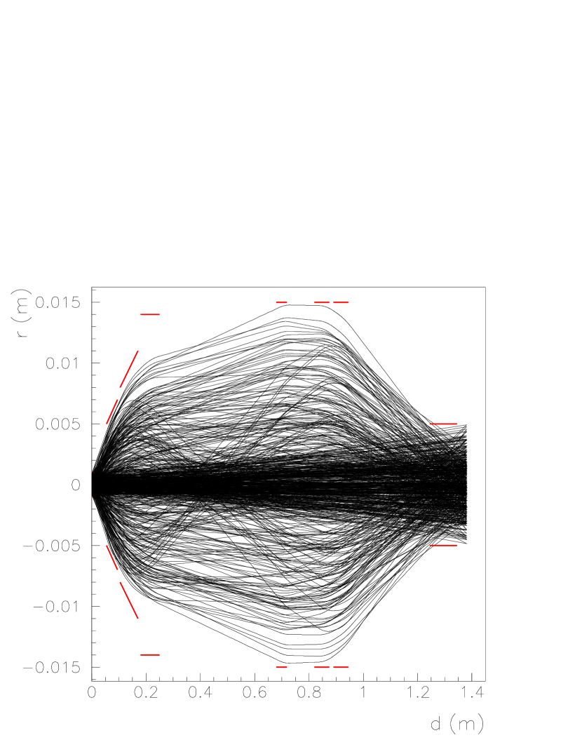
A variety of systems were studied, all under the assumption of and pole-tip fields of 1.5 T. A system utilizing 6 magnets was found to yield satisfying both separation of the atoms in the and states and focusing of the states into the feeding tube. Optimization of the parameters led to the system listed in Table 2. (The tracking calculations, yielding the magnet dimensions for the order to the manufacturer had been performed for a slightly different geometry.) The table gives the two distances, at which intensity measurements with the compression tube were performed. The Fig. 6 shows the projection of the trajectories of H atoms in the states, calculated for this system. One recognizes two groups of trajectories, one with an intermediate focus and another one with focusing into the feeding tube. The present result like those of other groups (see e.g., Ref. Lorentz_Dipl_1993 ) confirms the expectation Kubischta_1991 that the transmission as function of the atom velocity should show two maxima, one below and one above the most probable velocity.
| component | [T] | [mm] | [mm] | [mm] | [mm] |
|---|---|---|---|---|---|
| Nozzle orifice | 2.3 | 3.3 | |||
| 15.0 | |||||
| Skimmer | 4.4/30.4111Conical opening,the first number denotes the measured diameter of the entrance, the second that of the exit aperture. | 13.0 | |||
| 16.9 | |||||
| Diaphragm | 9.5/9.911footnotemark: 1 | 2.0 | |||
| 3.6 | |||||
| Magnet #1 | 1.630 | 10.40/14.1211footnotemark: 1 | 39.98 | 40.01 | |
| 9.4 | |||||
| Magnet #2 | 1.689 | 15.98/22.1211footnotemark: 1 | 64.04 | 65.01 | |
| 9.4 | |||||
| Magnet #3 | 1.628 | 28.04 | 94.00 | 70.01 | |
| 429.7 | |||||
| Magnet #4 | 1.583 | 30.04 | 94.02 | 38.01 | |
| 101.0 | |||||
| Magnet #5 | 1.607 | 30.06 | 94.00 | 55.01 | |
| 15.0 | |||||
| Magnet #6 | 1.611 | 30.02 | 94.04 | 55.00 | |
| 300.0 | |||||
| 337.0 | |||||
| Compr. tube | 10.0 | 11.0 | 100.0 |
The transmission of the system is defined as the fraction of tracks, ending within the entrance of the feeding tube, to those passing the diaphragm in front of the first sextupole magnet. For the four hyperfine states of hydrogen HFS , the calculations yield (for both ), and , and (for both ).
The performed tracking calculations do not account for intra-beam and residual-gas scattering. The calculated transmissions thus only allowed one to estimate upper limits of the expected atomic beam intensity into the feeding tube. For a primary molecular flow , the intensity with atoms mainly in the states and () was expected as
| (2) |
For the degree of dissociation a routine value of 0.8 (see e.g., Ref. Wise_et_al_1993 ) was assumed. is the solid angle covered by the collimator aperture. The factor 1/4 reflects the assumption that the four substates in the atomic beam from the nozzle are equally populated. For mbar /s or molecules/s one expects H atoms/s.
As described in the subsequent section, the rf transition units are used to change the relative occupation numbers of the states. The trajectory code allows one to simulate this change by assigning a of one of the states to the atoms before they pass a magnet. As an example, the medium-field transition unit (MFT) behind magnet No. 3 (see Fig. 1) brings H atoms from state into state . This is simulated by assigning to the atoms in the magnets and in the magnets , where they get deflected from the beam axis. This results in a small value . From this value and the above value the vector polarization is expected as
| (3) |
under the assumption of 100 % efficiency of the transition unit.
The design and the properties of the permanent sextupole magnets VACODYM were discussed in an earlier paper Vassiliev_et_al_2000 . To achieve the pole-tip field values of 1.5 T, each magnet was produced from 24 segments employing three different types of NdFeB compounds. The expected pole-tip values (Table 2) and the precise radial dependence within the magnet apertures were confirmed. For the first time the predicted high multipole components Halbach_1980 up to a 102-pole structure very near to the aperture surface could be measured Vassiliev_et_al_2000 .
After the field measurements, the magnets were encapsulated to prevent diffusion of hydrogen into the magnet material, which might deteriorate the magnetic properties, and to avoid the pumping of gas from the sintered magnet bodies. The housings were made from thin stainless steel cans of 0.2 mm thickness for the conical and cylindrical walls within the magnet apertures and 0.3 mm for the front and end covers. During the final welding to close the housings with magnets installed, the local temperature of the magnet material had to be kept below the Curie temperature of 60 ∘C. This was achieved by welding with the use of a pulsed 15 Hz Nd:YAG laser, delivering 1.1 J in a pulse of 2 ms FIL . Overlapping weld spots of 0.3 mm diameter, set around the adjacent circular, 0.2 mm thick weld lips, allowed one to finish the housings with leak rates /s. Inside the housings the magnets were fixed to suppress axial and rotational movements caused by the force of the adjacent magnets. Finally the free slits within the housings were filled by 20 mbar krypton to enable leak tests by mass spectroscopy.
II.7 Radio Frequency Transition Units
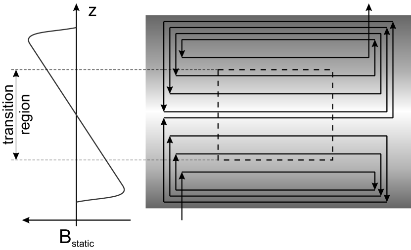
The ABS is equipped with three types of transition units, a weak field, a medium field, and a strong field rf transition unit (WFT, MFT, and SFT units). Together with the selecting properties of the sextupole magnets, they enable one to achieve all vector and tensor polarizations of the atomic hydrogen and deuterium gas in the storage cell. In all three units, transitions between the hyperfine states, split according to the Breit-Rabi diagram by a static magnetic field (see e.g., Ref. Haeberli_1967 ), are induced by the magnetic component () of an rf field, leading to changes in the population of the states. The static field consists of two parallel components, a homogeneous field and a superimposed weaker gradient field , both orthogonal to the beam direction. The field gradient along the beam direction is required to satisfy the condition of adiabatic passage Haeberli_1967 ; Abragam+Winter_1958 .
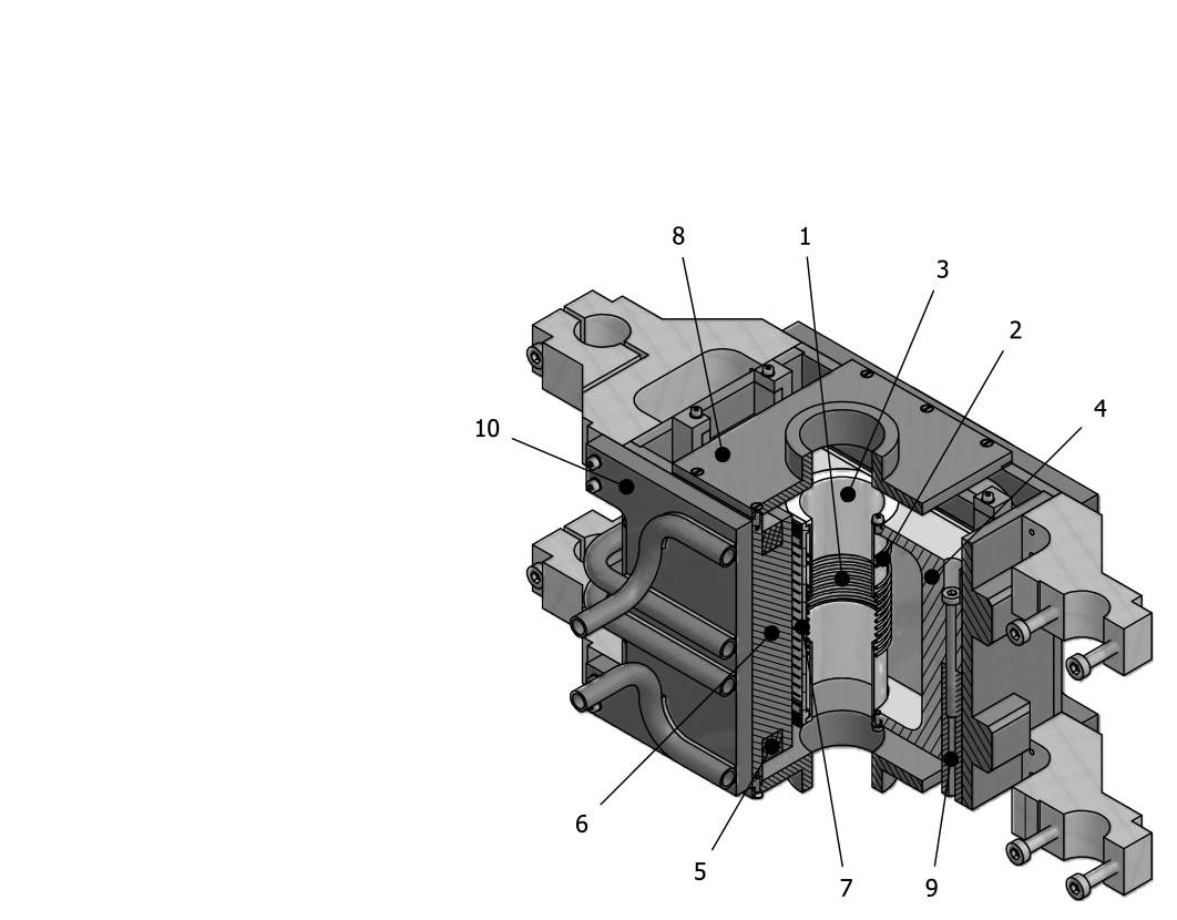
The assemblies of the WFT and the MFT units are similar Lorenz_Dipl_1999 . The layouts follow those of the units developed for the HERMES experiment Gaul+Steffens_1992 . In both units the rf field is produced by a coil with the axis along the beam direction, and consequently orthogonal to . The MFT unit is shown in Fig. 7. Figure 8 schematically shows one of the grooved aluminum frames with the windings producing the gradient field.
A WFT unit is operated in a weak magnetic field, 10 G for hydrogen and 5 G for deuterium, where the total atomic spin is a good quantum number. In hydrogen the levels , , and with magnetic quantum numbers , and , respectively, can be regarded as equally spaced. In deuterium the same holds for the four levels , , , and ) with , and , respectively, and for the two levels and with and , respectively. The magnetic component of the rf dipole field induces transitions between each pair of neighboring states with . transitions are forbidden. The interchange of the population between the states and in hydrogen, e.g., is caused by a two-quantum transition via the intermediate state . In the classical description of the adiabatic passage method Abragam+Winter_1958 the population change should not depend on the sign of the magnetic field gradient relative to the beam direction. An exact quantum-mechanical treatment Oh_1970 ; Schieck_2008 , however, indicates that cleaner population changes from state to in hydrogen and from state to in deuterium are obtained with a negative field gradient, i.e., a field decreasing in the beam direction. Deviations from adiabaticity are discussed in Ref. Oh_1970 ; Philpott_1987 .
The MFT unit is operated at higher values of , where the differences in the energy spacings of pairs of hyperfine states with allow one to select single transitions. Originally developed for an polarized alkali ion source Jaensch_et_al_1985 , the MFT unit now is a standard component in polarized hydrogen and deuterium sources as discussed, e.g., in Ref. Roberts_et_al_1992 . Appropriate choice of , , and the rf frequency allows one to induce selected transitions and in hydrogen or , , and in deuterium. Furthermore, the choice of the field gradient allows one to achieve consecutive transitions. As an example a negative field gradient in the MFT unit behind the first set of magnets, i.e., a field decreasing in beam direction, at a fixed rf frequency leads to the sequence of the transitions , , and finally in deuterium, leaving the state empty.
The SFT unit is used to induce transitions between states in the upper and lower hyperfine multiplet in hydrogen and deuterium. Contrary to the historical name, indicating a strong magnetic field, the SFT unit is operated with magnetic fields comparable to those used in the MFT unit. The transition frequencies are comparable with those of the hyperfine splitting (1420 MHz for hydrogen and 327 MHz for deuterium), and thus are much higher than those in the WFT and MFT units. The rf field in a SFT unit is produced by a twin-line resonator inside a Cu box tuned to the resonance Capiluppi_2012 . The SFT unit PNPI is shown in Fig. 9. Again, the layout follows that of the unit used in the HERMES experiment Gaul+Steffens_1992 . Two variable capacitors at the free ends of the conducting rods, fed by the rf power with a relative phase shift of 180 ∘, allow one to tune the device.
II.8 Slow Control System
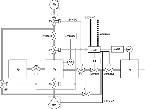
Industrial components, providing reliable and long-term support, were selected for the control system of the whole setup consisting of the ABS and the diagnostics tools, the storage cell positioning system, the Lamb-shift polarimeter, and the supply system of a calibrated flow of unpolarized molecular gas. The interlock system has been implemented on the basis of SIEMENS SIMATIC S7-300 family of programmable logic controllers. In order to unify the interfacing to the control computer, all front-end equipment is connected via the PROFIBUS DP fieldbus. The process control software was implemented using the Windows-based WinCC toolkit from SIEMENS. The system controls the operation of the pumps and the valves. It reads the pressure gauges and controls the regeneration cycles of the cryopumps. Via a control network, the temperature of the nozzle is stabilized within K. Furthermore, all power-supply units, rf generators and amplifiers are set and controlled. The whole variety of components to be controlled, the logical structure of the control and interlock system, and a separate device for parameter studies are described in Ref. Kleines_et_al_2006 .
III Studies of the free hydrogen jet
III.1 Atomic beam profile near the nozzle
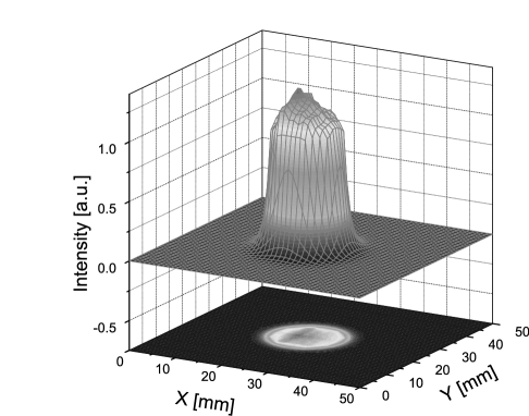
A novel device has been used to measure the profile of an atomic beam via the deposition of recombination heat on thin wires in a two-dimensional grid Vassiliev_et_al_1998 ; Vassiliev_et_al_1999 . Atoms stuck on the surface of gold-plated tungsten wires of 5 m diameter recombine and are reemitted as molecules. The recombination heat (4.476 eV per hydrogen molecule) leads to a change of temperature and, thus, resistance along each wire. The measurement of the resistance changes of all the wires in the grid allows one to deduce the center and the profile of the beam. Figure 10 shows the beam profile resulting with a wire grid positioned between skimmer and collimator, performed as a first proof of the method.
Later, such a device has been used to compare measured and calculated beam profiles along the beam axis between nozzle and skimmer Nass+Steffens_2009 .
III.2 Degree of dissociation of the free atomic jet
The dissociation of the primary molecules is achieved by the interaction of the electrons and the hydrogen or deuterium molecules in the plasma of the dissociator. The degree of dissociation of the beam from the nozzle depends on the rf power, applied to maintain the plasma, the primary molecular gas flow into the dissociator, and the temperature of the nozzle and the lower end of the discharge tube. These dependencies have been studied before installation of the sextupole magnets with a setup containing a crossed-beam quadrupole mass spectrometer Max_Dipl_1999 ; Max_et_al_1999 .
| (4) |
The admixture of molecules in an atomic beam is described by the degree of dissociation, where and are the densities of atomic and molecular hydrogen or deuterium in the beam. Other authors (e.g., Ref. Nass_et_al_2003 ) use the atomic and molecular intensities and in the definition of the degree of dissociation () in Eq. (4). The two definitions of are related by
| (5) |
This quantity was determined with the quadrupole mass spectrometer (QMS) in a conventional way as
| (6) |
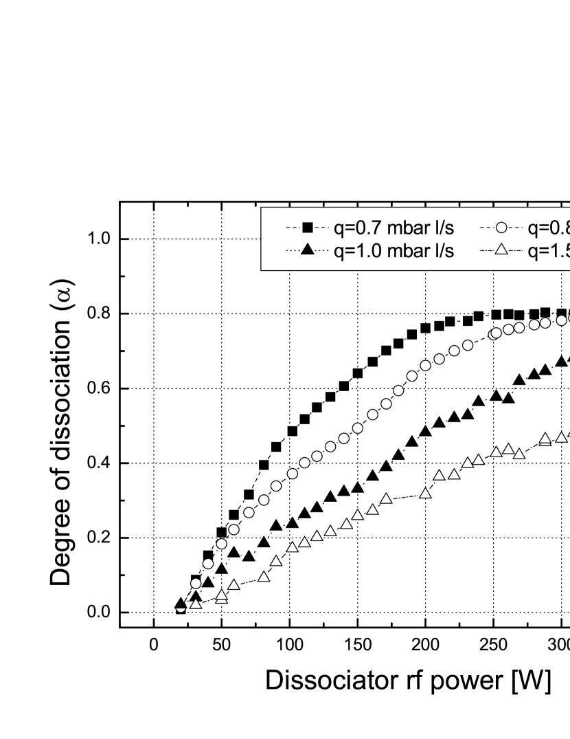
Here, denotes the atomic signal, corrected for dissociative ionization. The parameter was obtained following the method described in Ref. Koch+Steffens_1999 . The coefficient , accounting for the difference in atom and molecule velocity, was chosen as under the assumption of thermalization of the beam emerging from the nozzle. Furthermore, ionization CS accounts for the differences in ionization cross section for atomic and molecular hydrogen, and for the detection probability Max_Dipl_1999 . As an example of the parameter studies, Fig. 11 shows the deduced dependencies on the rf power for a set of primary molecular hydrogen gas flows. For typical flow values a saturation value around 0.8 was obtained.
IV Beam intensity
The intensity of the polarized beam from the ABS together with the layout of the storage cell determines the areal density of the target gas. The intensity of the beam has been measured with the use of a compression-tube setup Nekipelov1 ; Nekipelov2 , shown in Fig. 12,

to optimize the ABS operation parameters. The measurements were performed at a 300 mm distance from the compression-tube entrance to the last magnet and an inner tube diameter of 10.0 mm as set in the tracking calculations. The length of the compression tube of 100 mm was made equal to that of the foreseen feeding tube of the storage cell. The narrow tube around the compression tube on a support, based on the lower flange, separates the volume around the tube from the compression volume. The manipulator serves for centering the tubes and for intensity-profile measurements. The construction allows axial shifts of the compression tube by the manipulator and the use of tubes of different diameters.
The intensity of the beam, entering the compression volume through the compression tube, is measured via the pressure in the compression volume. It is determined by the equilibrium between the incoming beam intensity and the outgoing intensity . Under the assumption of a pure atomic beam and complete recombination in the compression volume
| (7) | |||||
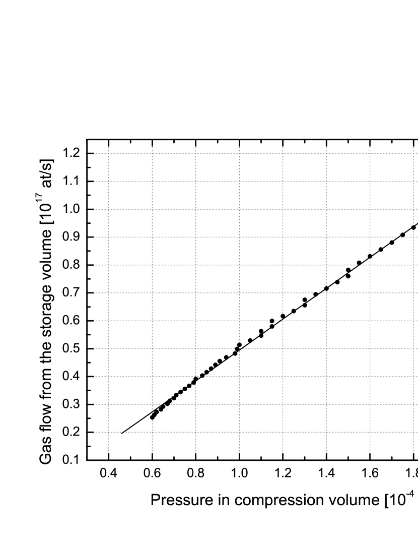
Here is the difference between the pressure measured in the compreesion volume and that in the ABS chamber V. The conductance of the compression tube, , is determined by the inner diameter of the tube, its length , the gas temperature , and the molar mass of the gas (given in cm and K, respectively) Roth_Vakuum . The factor 2 takes into account that the same pressure is measured in the hot-cathode gauge for (H atoms/s) and (H2 molecules/s). For mm, mm, K, and for hydrogen pressure differences on the order of mbar are expected for atomic hydrogen beam intensities in the order of atoms/s. The relation between and for hydrogen has been determined experimentally with the use of a source of calibrated molecular hydrogen gas flow Nekipelov1 ; Nekipelov2 , depicted in Fig. 3. The measured dependence with a linear fit is shown in Fig. 14. The calibration curve allows one to determine absolute values of of hydrogen and deuterium beams. The calibration for deuterium was deduced from the one for hydrogen by scaling with a factor , according to Eq. (7).


The dependences of on the dissociator-operation parameters primary molecular hydrogen flow , nozzle temperature , and dissociator power have been studied to find the optimum values. They are shown in the Figs. 15, 16, and 17, respectively, for different nozzle-orifice diameters. The figures show that for the hydrogen beam (states and ) with the standard operation parameters mbar /s, K, W, and with a nozzle-orifice diameter of 2.3 mm an intensity of particles/s is achieved, quite close to the earlier estimate from Eq. (2). Besides the dominant atomic component of H atoms, this value includes small admixtures of H atoms in state and molecular hydrogen. The first kind can be estimated with the use of the calculated transmissions (Sec. II.6) as . The amount of the second admixture has been measured as described below.
For the deuterium beam (states , , and ) the optimization procedure gave an intensity of particles/s, achieved with mbar /s, K, and W, slightly lower than those for hydrogen.
V Hydrogen beam profiles
Beam profiles were measured at various positions at various positions behind the last sextupole
magnet with the use of
a compression tube of reduced dimensions (5 mm diameter)
a crossed-beam quadrupole mass spectrometer, and
a supplementary method of reduction of MoO3 by hydrogen.
V.1 Measurements with the compression tube
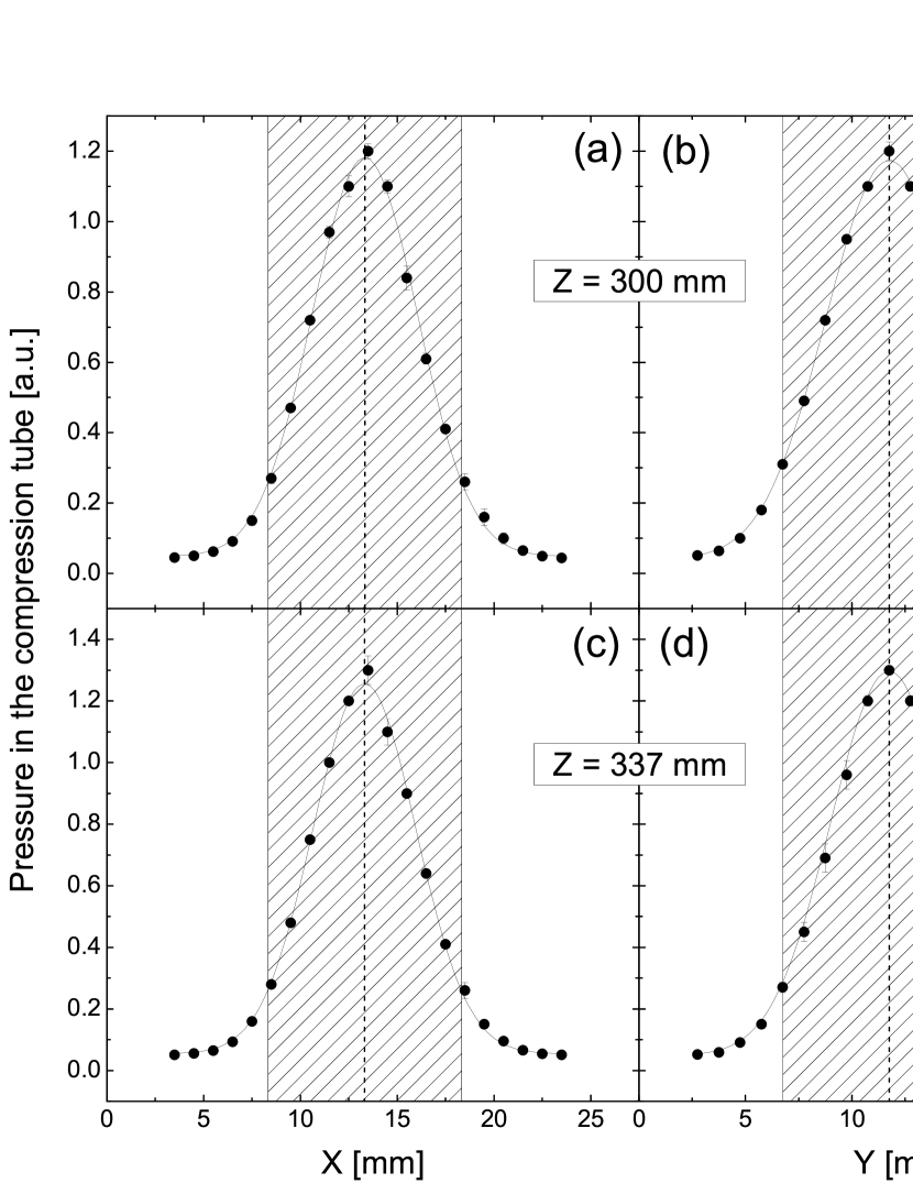
For the determination of the beam dimensions at two positions, 300 mm and 337 mm behind the last magnet, the compression tube setup (Fig. 12) was used, making use of the possibility of axial movement by the manipulator and of that to install a narrower and shorter compression tube of 5 mm diameter and 50 mm length to enhance the spatial resolution. The manipulator provided a lateral displacement of the compression tube by mm in and direction. The center coordinates of the geometrical axis of the source had been determined with the use of a bi-directional laser, centered inside the bore of the central support plate (see Fig. 1). The relative intensity distributions in the and planes, given by the measured pressure in the compression volume, are shown in Fig. 18. Fits by Gaussian distributions to the data yield full widths at half maximum mm, mm for the distributions measured at mm and mm, mm at 337 mm.
The center of gravity of the measured profile, defined as
| (8) |
where and give the position of the compression-tube axis and is the pressure measured in the compression volume. The resulting shows a deviation of 0.12 mm from the geometrical axis of the source. Furthermore, the data measured with the narrow compression tube of 2.5 mm radius can be used to derive the fraction of the beam entering the compression tube of 5 mm radius used in the intensity measurement of Sec. IV. The ratio
| (9) |
where is the distance of the compression-tube axis to the beam axis, yields .
V.2 Measurements with the QMS

The beam-profile studies of Sec. V.1 were extended with a setup utilizing a crossed-beam quadrupole mass spectrometer (QMS) in the setup of Fig. 19. Contrary to the measurements with the compression tube, those with the QMS allow to separate the atomic and molecular fractions in the beam. A 2 mm diameter aperture was installed at the entrance of the sensitive volume of the QMS to improve the resolution compared with that achieved by the compression tube of 5 mm diameter used in measurements of the preceding section. The layout of the setup, presented in Fig. 19, shows that in the present case the profile could not be measured at a distance of mm to the last magnet. Instead, measurements were performed at mm and, with installation of an extension tube, at mm. The manipulator enabled displacements of the aperture axis from the geometrical axis of the source in any direction within limits set by the bore diameter of the manipulator.
The first measured distribution of the atomic hydrogen (Fig. 20) showed a distinct deviation from azimuthal symmetry, indicating an insufficient relative alignment of nozzle and skimmer. The three threaded rods, supporting the dissociator with the nozzle via the
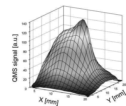
three-legged plate (label 2 in Fig. 1), allow one to vary the position of the nozzle relative to that of the skimmer while
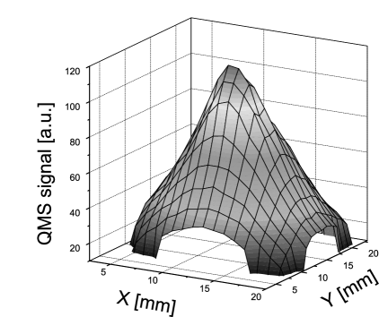
the source is running. This possibility has been used to find a nozzle position which results in an azimuthally symmetric distribution. The achieved symmetric distribution is shown in Fig. 21 and profiles of the atomic hadrogen component in the beam, measured in and direction at mm and mm, are presented in Fig. 22.
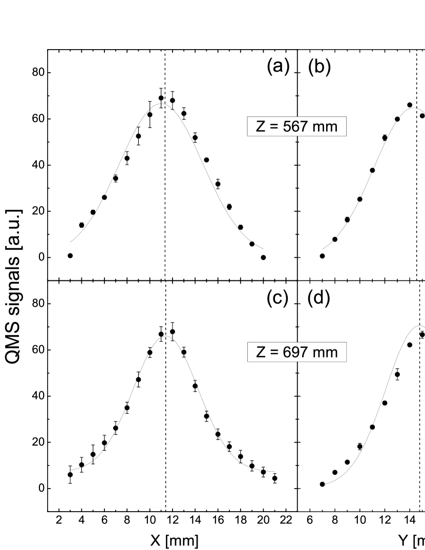
Fits by Gaussian distributions to the data yield full widths at half maximum mm, mm for the distributions measured at mm and mm, mm at 697 mm.
V.3 Reduction of MoO3 by hydrogen
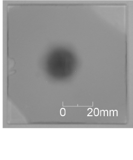
In addition to the compression tube and the QMS technique, a supplementary attempt was made to determine the beam profile by exposing molybdenium trioxide (a yellowish powder) on a glass plate to the beam. The principle of this method is based on the reduction of MoO3 to a lower oxide of blue colour. It first was used in the experiment to measure the magnetic moment of the hydrogen atom by splitting of the beam in an inhomogeneous magnetic field Phipps_Taylor_1927 .
This method is much simpler than the time-consuming measurements described in Secs. V.1 and V.2. It gives qualitative results as presented in Fig. 23. A quantitative analysis, however, requires development of the measuring technique (e.g., preparation of glass plates, study of the optimum exposure time, digital image processing).
V.4 Summary of the profile measurements
Table 3 summarizes results of the measurements of the ABS beam profile with the compression-tube and the QMS setup. The larger errors of the widths, measured with the QMS, are due to the lack of measurements with the dissociator switched off and the necessity to estimate the background signal from the existing data. Within the errors, the measured widths do not show a dependence on the distance from the last magnet. This facilitates to position the feeding tube of the storage cell in a wide range of a distances to the last magnet. The average values mm and mm agree within the errors and yield a common width of mm. The two-dimensional Gaussian distribution of this width allows one to estimate the fraction of the beam intensity injected into the compression tube or a feeding tube. For a tube of 10 mm diameter , comparable with given in Sec. V.1.
| z[mm] | [mm] | [mm] | |
|---|---|---|---|
| CT | 300 | ||
| CT | 337 | ||
| QMS | 567 | ||
| QMS | 697 |
VI Degree of dissociation
Besides the intensity of the atomic beam it is important to determine the molecular fraction in the beam. Molecules injected into the feeding tube, reduce the polarization of the target gas.
VI.1 Measurements with crossed-beam QMS
In addition to the data on the profile of the atomic hydrogen beam (Sec. V.2), data on the distributions of molecular hydrogen in the beam were taken, too, at the positions mm and 697 mm behind the last magnet. The relation between the degree of dissociation and the QMS signals by the atomic and molecular beam component was given above by Eq. (6). The coefficient , however, is chosen here under the assumption that the average velocity of the atoms is determined by the nozzle temperature of 65 K and that of the molecules by scattering and recombination on the ABS chamber walls at 290 K. This yields , in good agreement with Ref. Nass_et_al_2003 , where this coefficient was determined by the measured velocity distributions under similar conditions.
The measured profiles of the atomic fraction (identical to those of Fig. 21), those of the molecular fraction, and those of the degree of dissociation, deduced from Eq. (6), are collected in Fig. 24.
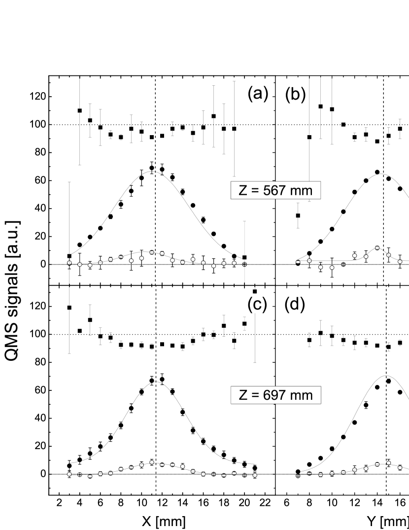
As it is seen from the figure, the distribution of the degree of dissociation shows a dip around the central line due to the higher density of molecular hydrogen originating from the nozzle. The mean value in an aperture of 10 mm diameter results as .
VI.2 Measurements with the Lamb-shift polarimeter
A cup in the quench chamber of the Lamb-shift polarimeter (LSP), described in Ref. Engels_et_al_2005_1 , allows one to measure the currents and of the and ions, extracted from the ionizer and separated by the Wien filter with the cesium evaporation and the spin filter switched off. The relation between the degree of dissociation and the measured currents is
| (10) |
Among the three coefficients, as for the measurement with the QMS. For the electron energy of about 100 keV, the ratio of dissociative to non-dissociative ionization of is Engels_et_al_2005_1
| (11) |
and the ratio between the ionization cross sections is ionization CS ; Engels_et_al_2005_1
| (12) |
VII Beam polarization
The Lamb-shift polarimeter was designed, built, and tested at Universität zu Köln Engels_et_al_2003 . It was used to measure and to optimize the polarization of the atomic hydrogen and deuterium beams delivered by the ABS. Details are found in Ref. Engels_et_al_2003 .
The vector polarization for hydrogen is defined by the relative hyperfine-state occupation numbers ,
| (13) |
for deuterium
| (14) |
Deuterium tensor polarization is given by
| (15) |
These polarizations can be derived from the measured Lyman- peak strengths by application of a number of correction factors Engels_et_al_2003 ; Engels_et_al_2005_1 .
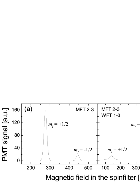
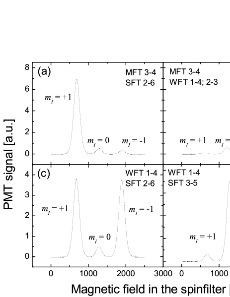
Typical Lyman spectra, measured with the polarized hydrogen and deuterium beam from the ABS, are shown in the Figs. 25 and 26.
| populated | |||
|---|---|---|---|
| state(s) | |||
| Hydrogen | - | ||
| - | |||
| Deuterium | |||
The polarization values for the hydrogen and the deuterium beam, derived from the Lyman- peak-strength ratios with application of the necessary corrections, are summarized in Table 4.
VIII Conclusions and Outlook
In this paper, we present the detailed description of the major components of the atomic beam source (ABS) for the polarized internal gas target of the magnet spectrometer ANKE in COSY-Jülich. The ABS was built for the purpose of extending the physics program of ANKE from unpolarized and single-polarized investigations with stored beams towards double-polarized experiments COSY152 , thus facilitating nuclear reaction studies involving , , and initial states.
The mechanical design took into account that at ANKE the source has to be mounted vertically and transversely movable together with the transverse motion of the spectrometer magnet D2. The design of the system of sextupole magnets took advantage of the developments in the field of rare-earth permanent magnets (NdFeB). Dedicated tools and methods were developed to determine and to optimize the source parameters, i.e., intensity, degree of dissociation, and polarization. Special emphasis was put on the measurements of the spatial distributions of the atomic and molecular beam near the focus, where the feeding tube of the storage cell is located. The ABS has been used in a number of investigations at ANKE, the commissioning effort to prepare the target for the use with polarized H is described in Ref. Max_et_al_2011 . Performed studies of the deuteron-charge exchange reaction are summarized in Ref. David M_et_al_2011 ; Rathmann_2011 , studies in near-threshold pion production are reported about in Ref. Sergej D_2011 .
The ABS resides at the ANKE target position for a few months per year only, thus during the remaining time it is used for other studies. It had been observed that the nuclear polarization in recombined hydrogen is partially retained after recombination Wise_et_al_2001 , as well as evidence for nuclear tensor polarization in recombined deuterium molecules v_d_Brand_et_al_1997 . In order to investigate this recombination process in more detail, a special setup has been developed in the framework of an ISTC project ISTC_2001 , and the recombination process for different cell-wall coatings, and different polarizations of the injected hydrogen or deuterium atoms as function of cell-wall temperature, strength of the magnetic holding field, and gas pressure in the cell is presently investigated Engels_et_al_2010 ; DFG ; Engels_et_al_2011 .
Appendix A Preparation of Discharge Tubes and Nozzles
A.1 Tube Treatment
One end of the discharge tube is machined at a 45∘ angle, while the other is kept flat. Both ends are then remelted and the tubes are tempered at 150 ∘C. The tubes are further treated according to the procedure described in Ref. Koch_Diss_1999 , which includes successive cleaning with acetone, methanol, distilled water, and subsequent rinsing by a 2:1 acid mixture of concentrated HF (40%) and HCl (32%) for 5 min. The tubes are then flushed by distilled water and dried.
A.2 Nozzle Treatment
The nozzles are cleaned in an ultrasonic bath of trichlorethylene, acetone, methanol, and finally distilled water, all at 50 ∘C. Anodizing takes place in sulfuric acid to form a thin layer of , as described in Ref. Koch_Diss_1999 . Afterwards they are immersed in distilled water for 30 min at 95 ∘C.
Acknowledgements.
The authors want to thank O.W.B. Schult, Institut für Kernphysik (IKP), Jülich, who initiated the polarization program of ANKE. Thanks go to the design office, the mechanical workshop, and especially to W.R. Ermer, all IKP. Valuable advice was received from the PINTEX collaboration at IUCF, from the target group at HERMES, especially N. Koch, and from D. Toporkov, BINP, Novosibirsk. The support by V. Koptev, PNPI, Gatchina, who regrettably passed away in January 2012, is gratefully acknowledged. Thanks go also to R. Poprawe and colleagues, Fraunhofer-Institut für Lasertechnik, Aachen, where the encapsulations of the magnets were laser-welded.References
-
(1)
A. Kacharava, F. Rathmann, and C. Wilkin, Spin Physics from COSY to FAIR,
COSY Experiment Proposal No. 152 (2005).
Available under http://arXiv:nucl-ex/0511028. - (2) W. Haeberli, in Proc. Int. Symp. on Polarization Phenomena of Nucleons, Karlsruhe 1965. Eds. P. Huber and H. Schopper, Experientia Supplementum 12, 64 (Birkhäuser Verlag, 1966).
- (3) E. Steffens and W. Haeberli, Rep. Progr. Phys. 66, 1887 (2003).
- (4) S. Barsov et al., Nucl. Instr. and Meth. A 462, 364 (2001).
- (5) R. Maier, Nucl. Instr. and Meth. A 390, 1 (1997).
- (6) K. Grigoryev et al., Proc. 14th International Workshop on Polarized Sources, Targets and Polarimetry (PSTP 2011), 12-16 September 2011, St.Petersburg, Russia, eds. K. Grigoryev, P. Kravtsov and A. Vasilyev, ISBN 978-5-86763-282-3, 61 (2011).
- (7) R. Engels et al., Rev. Sci. Instrum. 74, 4607 (2003).
- (8) R. Engels et al., Rev. Sci. Instrum. 76, 053305 (2005).
- (9) T. Wise et al., Nucl. Instr. and Meth. A 336, 410 (1993).
- (10) W.A. Dezarn et al., Nucl. Instr. and Meth. A 362, 36 (1995).
- (11) T. Rinckel et al., Nucl. Instr. and Meth. A 439, 117 (2000).
- (12) F. Stock et al., Nucl. Instr. and Meth. A 343, 334 (1994).
- (13) A. Nass et al., Nucl. Instr. and Meth. A 505, 633 (2003).
- (14) V. Derenchuk et al., Proc. Conf. Polarized Ion Sources and Polarized Gas Targets, Madison, WI, 1993. Eds. L.W. Anderson and W. Haeberli, AIP Conf. Proc. 293, 72 (American Institute of Physics, 1994).
- (15) H. Okamura et al., see Ref. Derenchuk_et_al_1994 , p. 84.
- (16) K. Hatanaka et al., Nucl. Instr. and Meth. A 384, 575 (1997).
- (17) Manufacturer Schiffer Metall- & Vakuumtechnik, 52428 Jülich, Germany.
- (18) Single-stage type RGS/120, refrigerating capacity 120 W at 80 K and 20 W at 30 K, Leybold Vacuum GmbH, 50968 Köln, Germany.
- (19) Mini UHV gate valve, series 010, VAT Germany GmbH, 85630 Grasbrunn, Germany.
- (20) Type F3 fomblin oil, Pfeiffer Vacuum GmbH, 35614 Asslar, Germany.
- (21) Model HU 1, Leybold Vacuum GmbH, 50968 Köln, Germany.
- (22) Manufacturer SK Industriemodell GmbH, 52531 Übach-Palenberg, Germany.
- (23) Type PFG 600 RF with automatic matchbox PFM 1500 A-IND, Hüttinger Elektronik GmbH, 79110 Freiburg, Germany.
- (24) W. Korsch, PhD Thesis, Philipps Universität Marburg (1990).
- (25) F. Stock et al., Int. Workshop on Polarized Beams and Polarized Gas Targets, Koeln, Germany, 1995. Eds. H. Paetz gen. Schieck and L. Sydow (World Scientific Publ. Co., 1996) p. 260.
- (26) The first number denotes the outer diameter and the second one the wall thickness.
- (27) Type Duran 8330, equivalent to Corning 7740 (Pyrex), Schott AG, 55122 Mainz, Germany.
- (28) Ultra-Kryomat RUL 80-D, Lauda Dr. R. Wobser GmbH, 97912 Lauda-Königshofen, Germany.
- (29) ODU-Kontakt GmbH, 84444 Mühldorf, Germany.
- (30) Handbook of Chemistry and Physics, Ed. R.C. East (The Chemical Rubber Co., 1973), p. E-10.
- (31) N. Koch and E. Steffens, Rev. Sci. Instrum. 70, 1631 (1999).
- (32) A. Vassiliev et al., Petersburg Nuclear Physics Institute Report NP-32-1997 No. 2175 (1997).
- (33) B. Lorentz, Diploma Thesis, Ruprecht-Karls-Universität Heidelberg (1993).
- (34) A. Nass and E. Steffens, Nucl. Instr. and Meth. A 598, 653 (2009).
- (35) W. Haeberli, Ann. Rev. Nucl. Sci. 17, 373 (1967).
- (36) A. Vassiliev et al., Rev. Sci. Instr., 71, 3331 (2000).
- (37) W. Kubischta, Proc. Workshop on Polarized Gas Targets for Storage Rings, Heidelberg, 23-26 September 1991, Eds. H.G. Gaul, E. Steffens, and K. Zapfe (Max-Planck-Institut für Kernphysik Heidelberg).
- (38) The labeling of the hyperfine states as , , , and for hydrogen and , , , , , and for deuterium follows that of Ref. Haeberli_1967 .
- (39) Produced from VACODYM 510HR, 383HR, and 400HR by Vacuumschmelze GmbH, 63412 Hanau, Germany.
- (40) K. Halbach, Nucl. Instr. and Meth. 169, 1 (1980).
- (41) Welding performed at Fraunhofer-Institut für Lasertechnik, 52074 Aachen, Germany.
- (42) A. Abragam and J.M. Winter, Phys. Rev. Lett. 1, 374 (1958).
- (43) S. Lorenz, Diploma Thesis, Friedrich-Alexander-Universität Erlangen-Nürnberg (1999).
- (44) H.-G. Gaul and E. Steffens, Nucl. Instr. and Meth. A 316, 297 (1992).
- (45) S. Oh, Nucl. Instr. and Meth. 82, 189 (1970).
- (46) H. Paetz gen. Schieck, Nucl. Instr. and Meth. A 587, 213 (2008).
- (47) R.J. Philpott, Nucl. Instr. and Meth. A 259, 317 (1987).
- (48) H. Jänsch et al., Hyperfine Interactions 22, 253 (1985).
- (49) A.D. Roberts et al., Nucl. Instr. and Meth. A 322, 6 (1992).
- (50) M. Capiluppi et al., http://theor.jinr.ru/~spin2012/talks/s6/Steffens.pdf (to be published in Physics of Elementary Particles and Atomic Nuclei, JINR, Russia, http://pepan.jinr.ru/pepan/eng/about/).
- (51) Manufactured by St. Petersburg Nuclear Physics Institute, 188300 Gatchina, Russia.
- (52) H. Kleines et al., Nucl. Instr. Meth. A 560, 503 (2006).
- (53) A. Vassiliev et al., Petersburg Nuclear Physics Institute Report EP-46-1998 No. 2260 (1998).
- (54) A. Vassiliev et al., Proc. Int. Workshop Polarized Sources and Targets, Erlangen, Germany, September 29 -October 2, 1999. Eds. A. Gute, S. Lorenz, E. Steffens (Universität Erlangen-Nürnberg, 1999), p. 200.
- (55) M. Mikirtytchiants, Diploma Thesis, St. Petersburg State Technical University (1999).
- (56) M. Mikirtytchiants et al., see Ref. Vassiliev_et_al_1999 , p. 478.
-
(57)
Y.K. Kim et al., Electron-impact cross section database, 2002,
http://pysics.nist.gov/PhysRefData/Ionization. - (58) M. Nekipelov, Diploma Thesis, St. Petersburg State Technical University (1999).
- (59) M. Nekipelov et al., see Ref. Vassiliev_et_al_1999 , p. 486.
- (60) A. Roth, Vacuum Technology (Elsevier, Amsterdam, 1996).
- (61) T.E. Phipps and J.B. Taylor, Phys. Rev. 29, 309 (1927).
- (62) M. Mikirtychyants et al., J. Phys.: Conf. Ser. 295, 012148 (2011).
- (63) D. Mchedlishvili et al., J. Phys.: Conf. Ser. 295, 012099 (2011).
- (64) F. Rathmann, J. Phys.: Conf. Ser. 295, 012006 (2011).
- (65) S. Dymov (for the ANKE collaboration), J. Phys.: Conf. Ser. 295, 012095 (2011).
- (66) T. Wise et al., Phys. Rev. Lett. 87, 042701 (2001).
- (67) J.F.J. van den Brand et al., Phys. Rev. Lett. 78, 1235 (1997).
- (68) International Science and Technology Center, Project No. 1861.
- (69) Work now financed by Deutsche Forschungsgemeinschaft, project 436 RUS 113/977/01.
- (70) R. Engels et al., Proc. 13th Int. Workshop on Polarized Sources, Targets and Polarimetry, Ferrara, Italy, September 7-11, 2009. Eds. G. Ciullo, M. Contalbrigo, P. Lenisa (World Scientific, 2011), p. 215.
- (71) R. Engels et al., J. Phys.: Conf. Ser. 295, 012161 (2011).
- (72) N. Koch, PhD Thesis, Friedrich-Alexander-Universität Erlangen-Nürnberg (1999).