Ultrafast tuneable optical delay line based on indirect photonic transitions
Abstract
We introduce the concept of an indirect photonic transition and demonstrate its use in a dynamic delay line to alter the group velocity of an optical pulse. Operating on an ultrafast time scale, we show continuously tuneable delays of up to 20 ps, using a slow light photonic crystal waveguide only 300 m in length. Our approach is flexible, in that individual pulses in a pulse stream can be controlled independently, which we demonstrate by operating on pulses separated by just 30 ps. The two-step indirect transition is demonstrated here with a 30% conversion efficiency.
pacs:
42.70.Qs, 42.82.-m, 42.65.ReIndirect transitions are well-known phenomena in solid state physics, most notably for electrons inside a semiconductor material, whereby the simultaneous absorption of a photon and a phonon results in a change of both energy and momentum Ashcroft and Mermin (1976). The corresponding optical analogue, the indirect photonic transition, has so-far been elusive. Several schemes have been proposed Winn et al. (1999); Yu and Fan (2009), that are based on the simultaneous temporal and spatial modulation of the refractive index, which induces the transition between two photonic states of different frequency and wavevector. Such an indirect photonic transition has, to our knowledge, not yet been observed, and the closest related experimental demonstrations are those of direct interband photonic transitions Dong et al. (2008).
In this Letter, we propose and demonstrate a simplified version of an intraband indirect photonic transition, whereby the frequency and the wavevector are altered in a two-step process. We also show that such an approach can form the core of an ultrafast, continuously tuneable delay line capable of bit-by-bit control, which we demonstrate by independently manipulating one pulse from a chain of two that are separated by just 30 ps.
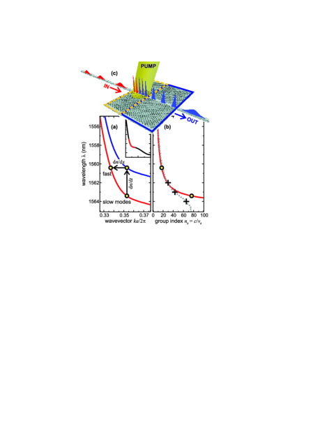
Our structure is designed to implement the transition of a light pulse from a slow state into a fast state of a photonic crystal waveguide, as illustrated in the dispersion diagram of Fig. 1(a) and the group index curve of Fig. 1(b). Such a transition requires a change in both frequency and wavevector, which can be provided by a stimulus that involves temporal and spatial perturbations of the waveguide, respectively. We realized this scheme by borrowing concepts from adiabatic light control Yanik and Fan (2004); Beggs et al. (2012); Kampfrath et al. (2010); Upham et al. (2010) and fibre optics Nuccio et al. (2010); Sharping et al. (2005).
As illustrated in Fig. 1(c), our fabricated structure is a single 300 m long modified version of a W1 photonic crystal waveguide Li et al. (2008), of period nm and hole diameter 249 nm, designed to exhibit the dispersion curve indicated by the red line of Fig. 1(a). Typically, such modifications aim to eliminate group velocity dispersion, but here we introduce it in a controlled fashion. The first 80 m is used as a tuning section (yellow box of Fig. 1(c)), where an input signal pulse undergoes adiabatic frequency conversion. This process is triggered by a pump-pulse that decreases the refractive index of the silicon through the ultrafast generation of free carriers Soref and Bennett (1987) with lifetimes 200 ps, which blue-shift the dispersion curve (blue curve in Fig. 1(a)). The signal pulse is also blue-shifted Kampfrath et al. (2010), as the photon momentum must be conserved: it is the generation of free carriers which provides the dynamics necessary for a vertical shift on the dispersion diagram. The interface between the pumped and unpumed region (blue box of Fig. 1(c)) provides the spatial modulation necessary for the horizontal transition, altering the signal wavevector. The remainder of the untuned section is there to ensure that the speed difference between the pumped and unpumped pulses can manifest itself as a change in delay.
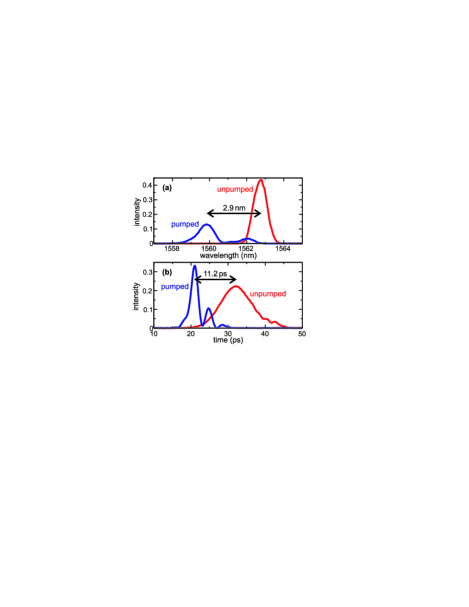
The occurrence of an indirect transition in our waveguide can be verified by recording the wavelength and the arrival time of the output signal pulse with and without pumping. The pump pulses are generated in a Ti:sapphire laser (centre wavelength 810 nm, duration 100 fs, repetition rate 80 MHz) and focussed onto the surface of the sample. A slit is used in the far-field to ensure the exclusive and homogeneous excitation of the waveguide in the tuning region. Synchronised probe pulses (1550 nm, 180 fs) are obtained from the same laser system: after passing through an optical parametric oscillator, they are coupled into the waveguide, with a mechanical delay stage used to set the timing between the pump and probe pulses. By measuring the waveguide time-dependent transfer function using the broadband 180-fs probe pulse, we have determined the response to an input pulse of duration 4.7 ps and centre wavelength 1563 nm. This approach Lepetit et al. (1995); Kampfrath et al. (2009) simply assumes that the waveguide is linear from the weak probe point of view, which we have verified experimentally. The extracted spectral output of this pulse from a ground state waveguide is shown by the red curve in Fig. 2(a). The transmission is measured as -3 dB (50%), with the primary losses due to propagation in the slow light regime (10 dB/mm). When tuned, the pumped input pulse is adiabatically shifted by 2.9 nm to a new centre wavelength of 1559.9 nm (blue curve in Fig. 2(a)) with a conversion efficiency of -5 dB (30%), manifesting the vertical transition in the band diagram. The losses in the conversion process arise from free-carrier absorption. The dispersion at the original wavelength results in a small fraction of the probe not being fully contained in the tuning region during pumping, thus leaving some residual light around 1562 nm.
In the time-domain, the frequency conversion translates into a change of the delay accumulated in the 220 m long untuned section (Fig. 2(b)). The unpumped pulse (red) travels with a group velocity of , and exits after 32.3 ps. The blue-shifted pumped pulse, however, travels with a higher group velocity of , exiting the waveguide 11.2 ps (or 2.5 pulse-widths) earlier than its unpumped counterpart, with -1.5 dB propagation loss (5 dB/mm) in the fast light regime. This difference in delay results from the change of the optical mode of the signal, and together with the measured wavelength conversion confirms the occurrence of an indirect transition. The group velocity dispersion at the original frequency accounts for the increased width of the unpumped pulse in the time-domain.
The physical mechanism of our two-step indirect transition should not be directly compared to that of an electron in a semiconductor, which rather finds its counterpart in the one-step process described in refs. Winn et al. (1999); Yu and Fan (2009). Our case is more similar to that of an electron experiencing a dynamic change in its atomic potential. As the changes in our waveguide are adiabatic Kampfrath et al. (2010), the signal pulse is continuously “guided” by the changes in the photonic band structure. The final result is an indirect transition, or adiabatic conversion, from an initial slow mode to a final fast mode of the same photonic band.
We adopt this approach, rather than the one-step photonic transition of ref. Yu and Fan (2009) for two reasons. First, we are able to use a homogeneous pump profile to excite the carriers, while a one-step transition requires a more complicated spatial profile that breaks the symmetry of the waveguide. Second, our approach is not limited by the modulation speed. We are limited instead by the magnitude of the carrier-induced index change, which allows us to achieve frequency shifts on the order of 400 GHz Kampfrath et al. (2010), rather than 20 GHz as was theoretically shown in ref. Yu and Fan (2009).
Our photonic crystal therefore acts as a tuneable delay line. Whereas previous quasi-static examples Vlasov et al. (2005); Melloni et al. (2008); Adachi et al. (2010) used the thermo-optic effect to tune the waveguide from the fast to the slow light regime, we use ultrafast generation of carriers to tune the pulse, converting it from slow to fast light, and offering the possibility of true bit-by-bit dynamic control of individual pulses with high efficiency and flexibility. The tuning section only needs to be as long as the pulse itself, whereas the delay function is performed by the following static section of arbitrary length. In contrast, conventional tuneable delay lines necessitate the tuning of the entire delay section, which incurs higher energy requirements in the case of thermo-optic tuning, or higher losses in the case of free-carrier tuning.
Note that the indirect transition as described above helps to favourably balance the two main loss mechanisms in the delay line. The pumped pulses are absorbed when they overlap with the free-carriers in the tuning section, but travel faster in the delay section, with lower propagation losses O’Faolain et al. (2010). In contrast, the unpumped pulses travel in the lossier slow light regime, but have no conversion losses. Dispersion compensation using suitably engineered waveguide sections can be used to eliminate the broadening of slow pulses, which is not an intrinsic limitation of our method.
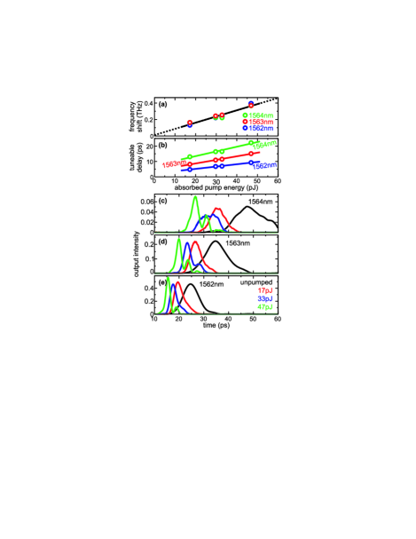
The delays demonstrated in Fig. 2 are continuously tuneable, either via the power of the pump, or by changing the input wavelength, as shown in Fig. 3. The frequency shift is a linear function of the pump energy (Fig. 3(a)) and independent of starting wavelength. This can be readily understood: the number of free-carriers generated is directly proportional to the absorbed energy, and the refractive index change is proportional to the carrier density Soref and Bennett (1987). The tuneable delay (Fig. 3(b)) depends on the local slope of the group velocity spectrum (grey line in Fig. 1(b)) at the starting wavelength, and the corresponding output pulses are shown in Fig. 3(c-e). For example, for a wavelength of 1564 nm, an absorbed pump-energy of 47 pJ gives a wavelength shift of 3 nm (0.37 THz) and a delay of 22.1 ps ( pulse widths).
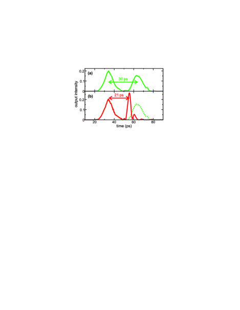
Finally, in order to demonstrate the potential of our ultrafast approach for bit-by-bit control of individual pulses, we have used two pulses of equal amplitude and centre wavelength of 1563 nm, duration 4.7 ps and separation 30 ps. Figure 4(a) shows the output when both pulses pass through the waveguide unpumped: the pulses travel in the ground state and exit the waveguide still separated by 30 ps. Overlapping the second probe-pulse with the pump in the tuning region allows for it to be manipulated independently of the first. The first pulse exits in the ground state, whereas the second pulse undergoes frequency conversion and delay. Figure 4(b) shows that the delay of the first pulse is not altered, whereas the second pulse exits 9 ps earlier than its unpumped counterpart, and the two pulses emerge just 21 ps apart.
We briefly note that optical buffers based on high-Q cavities have also been demonstrated Xu et al. (2007); Tanabe et al. (2009) using ultrafast tuning of the cavity resonance or Q-factor to trap and release pulses. However, such schemes suffer from limited bandwidth (the storage times are limited by the photon lifetime, necessitating high-Q cavities) and are much less flexible, as they only allow the delay of a single bit at a time. The loading of a pulse blocks the device until its release, such that the delay performance represents the intrinsic limitation on the dead-time. Our indirect transition device, in contrast, is scalable, in that the amount of delay available is simply related to the length of the waveguide (so the ultimate limitation is given by the propagation loss). The dead-time is related to the system recovery after carrier injection, which in principle can be reduced to tens of ps, as discussed below.
In conclusion, we have demonstrated the occurrence of a two-step indirect photonic transition based on adiabatic tuning in a photonic crystal waveguide, which we have applied in the realisation of an ultrafast, continuously tuneable integrated delay line. The indirect transition is achieved with a wavelength conversion and dispersion approach and has the major advantage of scaleability, as only the waveguide section containing the pulse is pumped. We have demonstrated a tuneable delay of 20 ps, corresponding to 4 pulse lengths, but suitably dispersion engineered and longer waveguides could achieve much longer fractional delays for the same pump power. The ultrafast nature of the tuneable delay is demonstrated by manipulating individual pulses of a pulse-stream, and our geometry could be used to manipulate multiple pulses at once. The major limitation of the current device is the dead-time, given by the carrier lifetime of 200 ps, which could be reduced by an order of magnitude by sweeping out the carriers via a reverse-biased pn junction. The scheme is fully compatible with silicon optoelectronics, as the required wavelength shift could also be produced by carrier injection/depletion Nguyen et al. (2011); Tanabe et al. (2010), removing the need for an external pump laser.
Hence, our indirect-transition based integrated tuneable delay line provides an important missing piece of the silicon photonics puzzle, bringing the full implementation of all-optical networks on silicon chips a step closer towards reality 111During the reviewing process, we became aware of arXiv:1110.5337v1, where an alternative method for achieving an indirect photonic transition Yu and Fan (2009) has been demonstrated..
Acknowledgements.
The authors acknowledge the support of EPSRC through the UK Silicon Photonics project, and the support of the Smart Mix Programme of the Netherlands Ministry of Economic Affairs and the Netherlands Ministry of Education, Culture and Science. This work is also supported by NanoNextNL of the Government of the Netherlands and 130 partners, and part of the research program of the Stichting voor Fundamenteel Onderzoek der Materie (FOM), which is financially supported by the Nederlandse organisatie voor Wetenschappelijk Onderzoek (NWO).References
- Ashcroft and Mermin (1976) N. W. Ashcroft and N. D. Mermin, Solid State Physics (Holt-Saunders, Philadelphia, 1976).
- Winn et al. (1999) J. N. Winn, S. Fan, J. D. Joannopoulos, and E. P. Ippen, Phys. Rev. B 59, 1551 (1999).
- Yu and Fan (2009) Z. Yu and S. Fan, Nature Photon. 3, 91 (2009).
- Dong et al. (2008) P. Dong, S. F. Preble, J. T. Robinson, S. Manipatruni, and M. Lipson, Phys. Rev. Lett. 100, 033904 (2008).
- Yanik and Fan (2004) M. F. Yanik and S. Fan, Phys. Rev. Lett. 92, 083901 (2004).
- Beggs et al. (2012) D. M. Beggs, T. F. Krauss, L. Kuipers, and T. Kampfrath, Phys. Rev. Lett. 108, 033902 (2012).
- Kampfrath et al. (2010) T. Kampfrath, D. M. Beggs, T. P. White, A. Melloni, T. F. Krauss, and L. Kuipers, Phys. Rev. A 81, 043837 (2010).
- Upham et al. (2010) J. Upham, Y. Tanaka, T. Asano, and S. Noda, Appl. Phys. Express 3, 062001 (2010).
- Nuccio et al. (2010) S. R. Nuccio, O. F. Yilmaz, X. Wang, J. Wang, X. Wu, and A. E. Willner, Opt. Lett. 35, 1819 (2010).
- Sharping et al. (2005) J. Sharping, Y. Okawachi, J. van Howe, C. Xu, Y. Wang, A. Willner, and A. Gaeta, Opt. Express 13, 7872 (2005).
- Li et al. (2008) J. Li, T. P. White, L. O’Faolain, A. Gomez-Iglesias, and T. F. Krauss, Opt. Express 16, 6227 (2008).
- Soref and Bennett (1987) R. Soref and B. Bennett, IEEE J. Quantum Electron. 23, 123 (1987).
- Lepetit et al. (1995) L. Lepetit, G. Cheriaux, and M. Joffre, J. Opt. Soc. Am. B 12, 2467 (1995).
- Kampfrath et al. (2009) T. Kampfrath, D. M. Beggs, T. F. Krauss, and L. K. Kuipers, Opt. Lett. 34, 3418 (2009).
- Vlasov et al. (2005) Y. A. Vlasov, M. O’Boyle, H. F. Hamann, and S. J. McNab, Nature 438, 65 (2005).
- Melloni et al. (2008) A. Melloni, F. Morichetti, C. Ferrari, and M. Martinelli, Opt. Lett. 33, 2389 (2008).
- Adachi et al. (2010) J. Adachi, N. Ishikura, H. Sasaki, and T. Baba, IEEE J. Sel. Topics Quantum Electron. 16, 192 (2010).
- O’Faolain et al. (2010) L. O’Faolain, S. A. Schulz, D. M. Beggs, T. P. White, M. Spasenović, L. Kuipers, F. Morichetti, A. Melloni, S. Mazoyer, J. P. Hugonin, P. Lalanne, and T. F. Krauss, Opt. Express 18, 27627 (2010).
- Xu et al. (2007) Q. Xu, P. Dong, and M. Lipson, Nature Phys. 3, 406 (2007).
- Tanabe et al. (2009) T. Tanabe, M. Notomi, H. Taniyama, and E. Kuramochi, Phys. Rev. Lett. 102, 043907 (2009).
- Nguyen et al. (2011) H. C. Nguyen, Y. Sakai, M. Shinkawa, N. Ishikura, and T. Baba, Opt. Express 19, 13000 (2011).
- Tanabe et al. (2010) T. Tanabe, E. Kuramochi, H. Taniyama, and M. Notomi, Opt. Lett. 35, 3895 (2010).
- Note (1) During the reviewing process, we became aware of arXiv:1110.5337v1, where an alternative method for achieving an indirect photonic transition Yu and Fan (2009) has been demonstrated.