High Rate Resistive Plate Chamber for LHC detector upgrades
Abstract
The limitation of the detection rate of standard bakelite resistive plate chambers (RPC) used as muon detectors in the LHC experiments has prevented the use of such detectors in the high rate regions in both CMS and ATLAS detectors. One alternative to these detectors are RPCs made with low resistivity glass plates (), a beam test at DESY has shown that such detectors can operate at few thousand Hz/cm2 with high efficiency( ).
keywords:
Gaseous detectors , GRPC , High Rate DetectorsPACS:
29.40.Cs , 29.40.Gx , 29.40.Vj1 Introduction
RPCs are powerful detectors used in many HEP physics experiments. Their good time resolution and efficiency, in addition to their simplicity and low cost make them excellent candidates for very large area detectors. The high resistivity of glass plates helps to prevent discharge damage in these detectors, but this feature represents a weakness when it comes to their use in high rate environments.
A semi-conductive glass RPC (GRPC) is a solution to overcome this issue. The low resistivity of its doped glass accelerates the absorption of the avalanche’s charge created when a charged particles crosses the RPC. A recent beam test at DESY in January 2012 with a high rate electron beam constitutes a validation of this new concept.
The GRPC detector is based on the ionization produced by charged particles in a gas gap. A typical gas mixture is TFE(), and , contained in a gap between 2 glass plates. A high voltage between and was applied on the glass through a resistive coating, assuring the charge multiplication of initial ionizations in avalanche mode with a typical gain of .
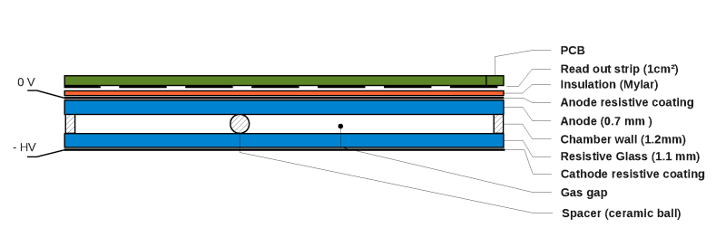
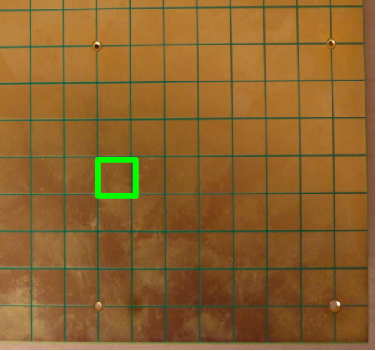
The new aspect of this detector is the low resistivity of the doped silicate glass (less then , compared to the typical of float glass), provided by Tsinguha University following a new process [1]. The glass plate thickness is for the cathode and for the anode. The resistive coating is colloidal graphite of resistivity. The gas was uniformly distributed in the chamber using the channeling-based system. Ceramic balls with diameter were used as spacers. The total GRPC thickness was . The signal was collected by copper pads (figure 1c) connected to a semi-digital readout system with 3 thresholds, identical to the one equipping the GRPC chambers used in the SDHCAL prototype developed within the CALICE collaboration [2][3].
2 DESY test beam
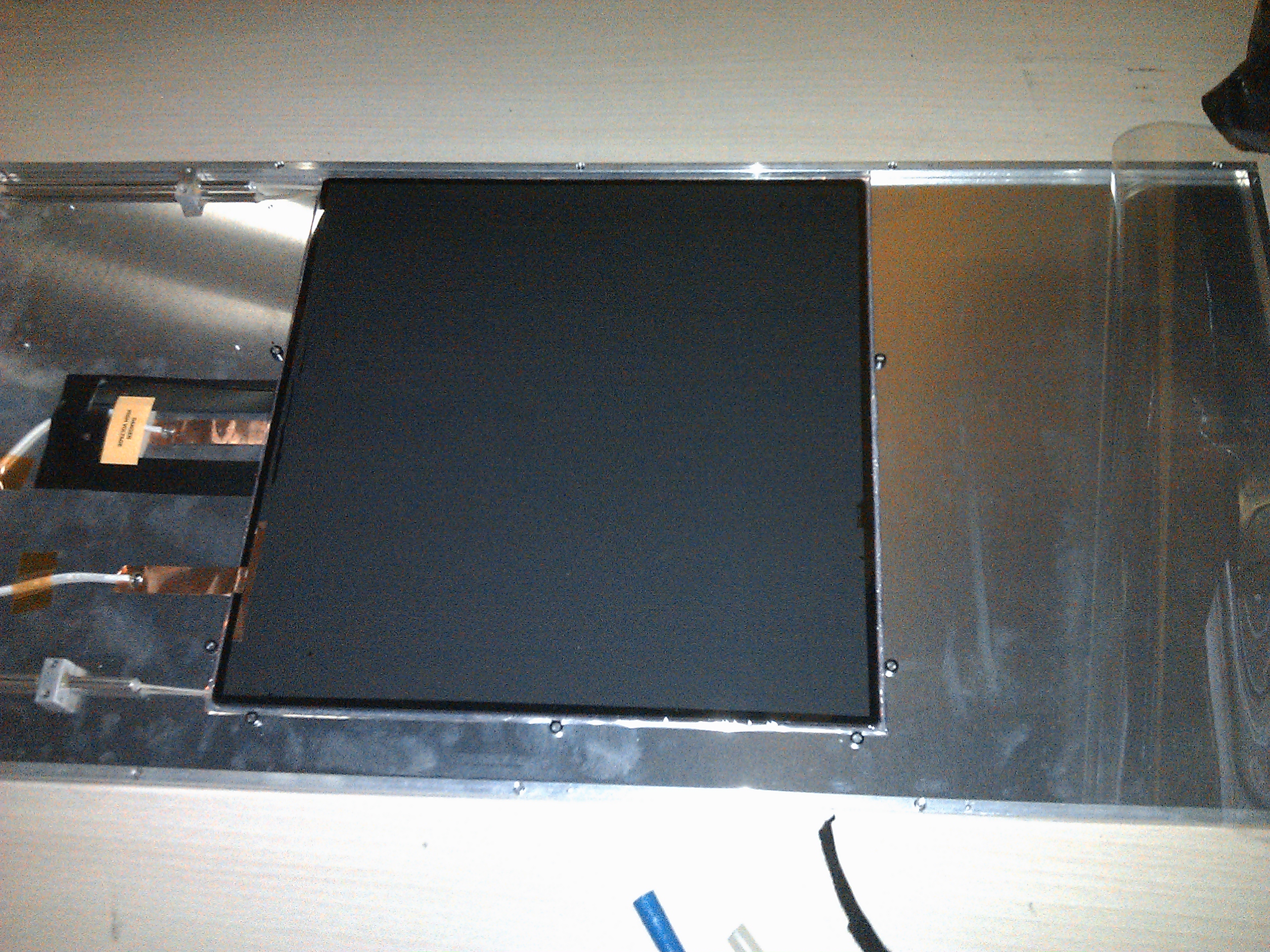
Four area RPCs were built following the design shown in figure 1a and were tested at DESY in January 2012. The DESY II synchrotron provides an intense and continuous electron beam with an energy up to . The particle rate depends on the beam energy,with a maximum of . The beam size is a few . Two scintillator detectors were placed upstream of the detector. Their role was to measure the beam rate.
One additional GRPC made with standard glass was added to the setup.
3 Results & discussion
3.1 GRPC performances
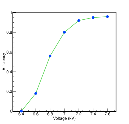
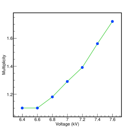
The local efficiency and multiplicity were measured by using 3 chambers to reconstruct particle tracks and determining the expected hit position in the 4th. The multiplicity is defined as the number of fired pads within of the expected position. The efficiency is the fraction of tracks with . The efficiency (3a) and multiplicity (3b) were measured as function of the polarization high voltage. The same threshold was used for all voltages. The threshold value is fixed at and was chosen as the working point, giving .
3.2 Running in a high rate beam
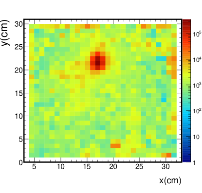
The scintillator detectors were used to determine the total particle flux, which was then divided by the beam RMS area () to obtain the rate by unit area. The measured (, ) for different beam rates are plotted in figure 4.
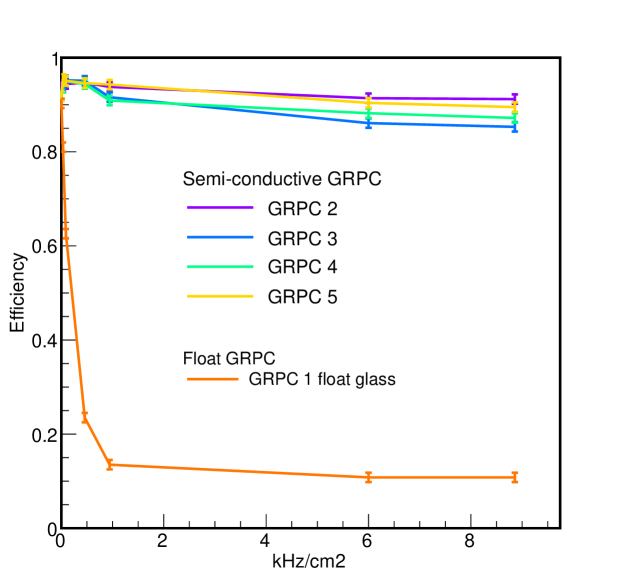
The chamber with standard float glass (GRPC 1) becomes inefficient at rate exceeding one hundred (above the efficiency is below ) while the semi-conductive chambers (GRPC 2-5) maintain a high efficiency until at least .
4 Conclusion
Semi conductive glass RPCs were tested at DESY in a high rate electron beam, producing very encouraging results; it has been shown that the main weakness of standard RPCs, namely the drop of efficiency at high rate, is clearly overcome, with efficiencies remaining at around at rate of . This feature, combined with GRPC capability to provide precise time measurement, makes them an excellent candidate for future LHC muon detector upgrades. Additional studies on their aging under high rate conditions are underway. A multi-gap version is also under investigation.
References
- [1] Wang, Yi; Wang, Jingbo; Yan, Qiang; Li, Yuanjing; Cheng, Jianping; , ”Study on the performance of high rating MRPC,” Nuclear Science Symposium Conference Record, 2008. NSS ’08. IEEE , vol., no., pp.913-916, 19-25 Oct. 2008 doi: 10.1109/NSSMIC.2008.4774543
- [2] Kieffer, R.; Laktineh, I.B.; Lumb, N.; Bedjidian, M.; Donckt, M.V.; Han, R.; Mirabito, L.; , ”Development of new kind of GRPC for a semi-digital hadronic calorimeter,” Nuclear Science Symposium Conference Record (NSS/MIC), 2010 IEEE , vol., no., pp.1468-1471, Oct. 30 2010-Nov. 6 2010 doi: 10.1109/NSSMIC.2010.5874016
- [3] Laktineh, I.; , ”Development of a semi-digital hadronic calorimeter using GRPCs for future linear collider experiments,” Nuclear Science Symposium Conference Record (NSS/MIC), 2009 IEEE , vol., no., pp.100-102, Oct. 24 2009-Nov. 1 2009 doi: 10.1109/NSSMIC.2009.5401858
-
[4]
AIDA DESY II
http://adweb.desy.de/$∼$testbeam/