Room temperature electrically tunable broadband terahertz Faraday effect
The terahertz (THz) frequency range (0.1-10 THz) fills the gap between the microwave and optical parts of the electromagnetic spectrum. Recent progress in the generation williams_nphot_2007 and detection wanke_nphot_2010 of the THz radiation has made it a powerful tool for fundamental research and resulted in a number of applications tonouchi_nphot_2007 ; jepsen_lpr_2011 . However, some important components necessary to effectively manipulate THz radiation are still missing. In particular, active polarization and phase control over a broad THz band would have major applications in science and technology. It would, e.g., enable high-speed modulation for wireless communications federici_jap_2010 and real-time chiral structure spectroscopy of proteins and DNA nafie_arpc_1997 ; xu_spie_2003 . In physics, this technology can be also used to precisely measure very weak Faraday and Kerr effects, as required, for instance, to probe the electrodynamics of topological insulators maciejko_prl_2010 ; shuvaev_2012 . Phase control of THz radiation has been demonstrated using various approaches. They depend either on the physical dimensions of the phase plate (and hence provide a fixed phase shift) masson_ol_2006 ; strikwerda_oe_2009 ; saha_oe_2010 or on a mechanically controlled time delay between optical pulses (and hence prevent fast modulation) shimano_jjap_2005 ; amer_apl_2005 ; dai_prl_2009 . Here, we present data that demonstrate the room temperature giant Faraday effect in HgTe shuvaev_prl_2011 can be electrically tuned over a wide frequency range (0.1-1 THz). The principle of operation is based on the field effect in a thin HgTe semimetal film. These findings together with the low scattering rate in HgTe open a new approach for high-speed amplitude and phase modulation in the THz frequency range.
The idea behind our experiments is to exploit the strong interaction between a solid-state plasma and THz radiation wang_nphys_2010 . Because of this interaction, left- and right-handed circularly polarized THz waves have different complex refraction indices when a magnetic field is applied palik_rpp_1970 . Recently, this characteristic property has been proposed to realize broadband THz modulators and phase plates based on electron-doped InSb crystals arikawa_oe_2012 . However, there are two problems in the realization of such devices for practical applications. First, the giant Faraday effect in InSb does not survive at room temperature. Second, this approach requires fast modulation of the applied magnetic field with an amplitude of several hundreds mT, which is a rather challenging demand.
In semimetals with zero (or very small) band gap, such as HgTe, the electron plasma exists in undoped samples, due to the thermal activation of electrons. The ability to use such undoped HgTe layers results in a very high electron mobility and, consequently, we have been able to demonstrate the giant Faraday effect even at room temperature shuvaev_prl_2011 .
To achieve control over the Faraday effect in a constant magnetic field, we have now fabricated devices fitted with transparent gate electrodes, which allow to change the carrier density and thus the properties of the electron plasma in the HgTe layer. By applying a moderate voltage to these gates we are able to control the Faraday rotation and Faraday ellipticity, i.e., amplitude, phase shift, and polarization of the THz radiation at room temperature.
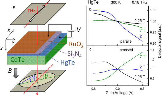
The THz experiments have been carried out in Faraday geometry as shown schematically in Fig. 1a. In this geometry the external magnetic field is parallel to the propagation direction of the THz radiation. The incident polarization is linear and the polarization of the transmitted radiation is detected by a wire grid analyzer. Further experimental details are given in the Supplementary Material. All experiments presented here have been carried out at room temperature. Our estimations suggest that the concentration of carriers confined to the topological surface state in this material shuvaev_2012 ; hancock_prl_2011 is comparable with the concentration of carriers occupied bulk states.
As shown in Fig. 1 bc, we observe a substantial variation of the amplitude of the transmitted signal as a function of gate voltage, both in parallel () and in crossed () polarizer geometry. Consequently, the Faraday rotation and ellipticity can be controlled by using a moderate electric voltage. In a first approximation, the observed changes may be attributed to the gate dependence of the effective charge density in the HgTe film. As will be shown below, not only the density, but all electrodynamic parameters of the HgTe are affected by the gate voltage. We mention already at this point that the response of the THz signal is asymmetric with the sign of the gate voltage, which is probably due to carrier trapping at the interface between HgTe and the gate insulator. We also observed hysteresis effect when tuning the gate voltage beyond certain critical value.
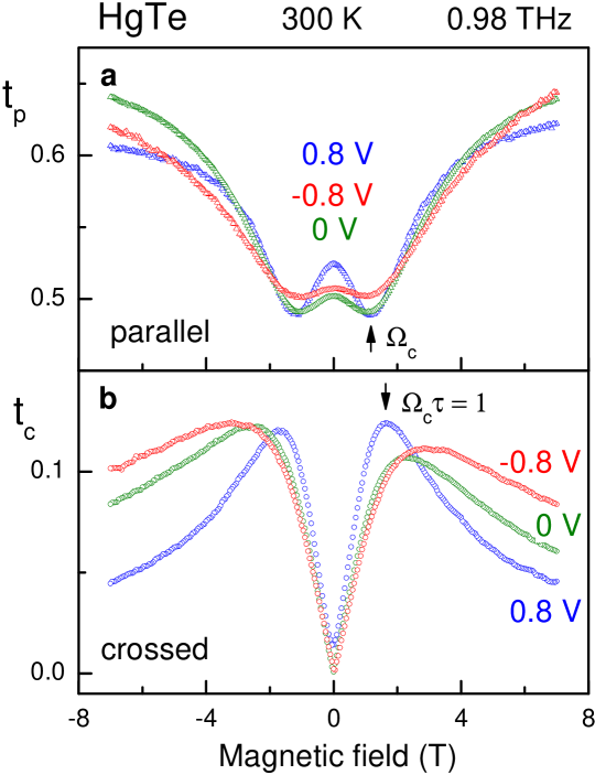
In order to characterize the electron dynamics in HgTe under applied gate voltage, a set of experiments at different magnetic fields and THz frequencies has been carried out. Figure 2 demonstrates the magnetic field dependencies of the magnetooptical signal of the HgTe film at three different gate voltages. The transmission amplitude for parallel polarizers (Fig. 2a) shows a clear minimum at a frequency-dependent field position which corresponds to the cyclotron resonance in HgTe . The width of the minimum in is directly connected to the scattering rate of electrons. As the width in Fig. 2a changes strongly with gate voltage, a variation of the characteristic scattering time is evident.
Figure 2b shows the amplitude of the transmission in crossed polarizer geometry. All curves reveal a characteristic maximum at a magnetic field around T. As shown in the Supplementary material [Eq. (10)], this maximum corresponds to a field value of and it allows for an independent determination of . Again, a strong variation of the maximum is observed in the field dependence of , which confirms the variation of the scattering time with gate voltage.
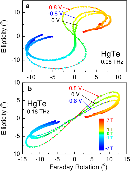
In addition to the transmission amplitude, phase information has been obtained using a Mach-Zehnder interferometric arrangement. From these experiments, the polarization state of the transmitted THz radiation can be fully polarized, including Faraday rotation and ellipticity. These data are shown in Fig. 3 for the parameter range accessible in our setup ( and ). The data in Fig. 3 are given for two different frequencies, close to the upper and the lower limits of our spectrometer. From the Faraday ellipticity vs. Faraday rotation diagram of Fig. 3 one can see that a desired polarization state can be set by varying either magnetic field or gate voltage.
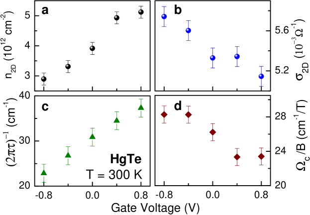
The observed gate dependence of the magnetooptical spectra can be well interpreted within the Drude model. The details of the characterization procedure and extraction of the electrodynamic parameters are given in the Supplementary Material. In brief, we fit simultaneously the magnetic field dependencies using charge density (), scattering rate () and cyclotron frequency (in terms of ) as the only fitting parameters. By repeating this fit for different gate voltages, we determine how these parameters depend on , as shown in Fig. 4. Two-dimensional electron conductivity derived from the other parameters as
| (1) |
is also shown in Fig. 4.
As expected, a strong variation of the electron density with gate voltage (nearly a factor of two) is observed (Fig. 4a). Assuming the simple capacitor formula to estimate the density variation, we obtain cm-2 per Volt. Here is the permittivity of the free space and is the dielectric constant of insulating layer. This is in a reasonable agreement with our experimentally observed value of cm-2V-1. Where again the difference with the capacitor model likely results from carrier trapping at the interface.
Contrary to the increase of the electron density with the gate voltage, the conductivity (, Fig. 4b) is a decreasing function of . This is rather unusual and can conceivably be explained by increased carrier scattering (, Fig. 4c) at the interface for larger gate voltages. Finally, we observe that the cyclotron frequency depends on the gate voltage as well, Fig. 4d. This result is expected for the Dirac surface states in HgTe with . It can be also caused by the deviation from ideal parabolic dispersion of bulk electrons in HgTe.
All results presented here have been obtained at room temperature, suggesting practical applications, such as fast phase and amplitude modulation or direct control of the polarization state by gate voltage and/or magnetic field. As the observed tuning of the THz radiation is due to modulation of the electron conductivity in the HgTe layer and is obtained by purely electrical means, it should be possible to achieve rather high modulation speed, comparable to this obtained with high electron mobility transistors (HEMT). The modulation amplitude is as large as several degrees per Volt, and we believe that it can be further improved by optimizing parameters of the gate material, insulating barrier and HgTe layer.
Acknowledgements
This work was supported by the by the German Research Foundation DFG (SPP 1285, FOR 1162) the joint DFG-JST Forschergruppe on ’Topological Electronics’, the ERC-AG project ’3-TOP’, and the Austrian Science Funds (I815-N16).
Supporting Online Material
The sample studied in this work is a coherently strained 100-nm-thick nominally undoped HgTe layer, grown by molecular beam epitaxy on an insulating CdTe substrate becker_pss_2007 . A 3 nm thin layer has been used as a gate electrode and 10 nm thick Si3N4 layer as an insulating barrier. The gate electrode transmits approximately 80 % of the terahertz radiation and revealed no own Faraday rotation signal. The amplitude of the gate voltage has been limited to V to avoid an electrical breakdown of the insulating layer.
Transmittance experiments at terahertz frequencies (0.1 THz 1 THz) have been carried out in a Mach-Zehnder interferometer arrangement volkov_infrared_1985 ; pimenov_prb_2005 which allows measurement of the amplitude and phase shift of the electromagnetic radiation in a geometry with controlled polarization. Using wire grid polarizers, the complex transmission coefficient can be obtained both in parallel and crossed polarizers geometry. Static magnetic fields, up to Tesla, have been applied to the sample using a split-coil superconducting magnet.
To interpret the experimental data we use the ac conductivity tensor obtained in the classical (Drude) limit from the Kubo conductivity of topological surface states (see e.g. Ref. tse_prb_2011 ). The diagonal, , and Hall, , components of the conductivity tensor as functions of THz frequency can be written as:
| (2) | |||
| (3) |
Here is the cyclotron frequency, is the dc conductivity, is the magnetic field, , , , and are the Fermi velocity, Fermi wave-number, charge, and scattering time of the carriers, respectively. For the Dirac spin-helical surface states the Fermi wave-number depends on the 2D carrier density, , through relation , with no spin degeneracy. For massive carriers the cyclotron resonance frequency can be written as , where is the effective electron mass in the parabolic approximation.
For a free standing film and neglecting any substrate effects, the complex transmission coefficients in parallel () and crossed () polarizers geometry can be written as:
| (4) | |||
| (5) |
Here and are effective dimensionless 2D conductivities, defined as: and with the HgTe film thickness nm and the vacuum impedance . In order to take into account the influence of the substrate a transfer matrix formalism berreman_josa_1972 ; shuvaev_epjb_2011 ; shuvaev_prl_2011 is utilized. The electrodynamic properties of the CdTe substrate are obtained in a separate experiment on a bare substrate.
According to Eq. (4), the transmittance in parallel polarizers () depends mainly on . The minima in roughly correspond to the cyclotron resonance energy and they scale with magnetic field. This may be understood by taking into account that for our film and Eqs. (4,5) simplify to:
| (6) |
In the limit , Eq. (2) may be approximated by
| (7) |
which leads to a resonance like feature in and for . Thus, the positions and widths of the minima in Fig. 2a are directly connected to Fermi velocity () for linear dispersion [or the effective mass () for parabolic dispersion] and the scattering rate () of the electrons.
The polarization rotation and the ellipticity are obtained from the transmission data using:
| (8) | |||
| (9) |
Here and the definitions of are shown schematically in Fig. 1a. A direct interpretation of the complex Faraday angle is in general not possible because of the interplay of and in the data.
In the low frequency limit () Eq. (3) simplifies to the static result:
| (10) |
The last expression has a maximum at , which leads to maxima in (Eqs. (5, 6) and Fig. 2b) and in at about the same field value. Therefore, the Faraday angle provides a direct and an independent way of obtaining the scattering rate .
References
- (1) B. S. Williams. Terahertz quantum-cascade lasers. Nat. Photon., 1(9):517, Sep 2007.
- (2) M. C. Wanke, E. W. Young, C. D. Nordquist, M. J. Cich, A. D. Grine, C. T. Fuller, J. L. Reno, and M. Lee. Monolithically integrated solid-state terahertz transceivers. Nat. Photon., 4(8):565, Aug 2010.
- (3) M. Tonouchi. Cutting-edge terahertz technology. Nat. Photon., 1(2):97, Feb 2007.
- (4) P. U. Jepsen, D. G. Cooke, and M. Koch. Terahertz spectroscopy and imaging - modern techniques and applications. Laser Photonics Rev., 5(1):124, May 2011.
- (5) J. Federici and L. Moeller. Review of terahertz and subterahertz wireless communications. J. Appl. Phys., 107(11):111101, Jun 2010.
- (6) L. A. Nafie. Infrared and raman vibrational optical activity: Theoretical and experimental aspects. Annu. Rev. Phys. Chem., 48(1):357, 1997.
- (7) J. Xu, J. Galan, G. Ramian, P. Savvidis, A. Scopatz, R. R. Birge, S. J. Allen, and K. Plaxco. Terahertz circular dichroism spectroscopy of biomolecules. In J. O. Jensen and J. M. Theriault, editors, Chemical And Biological Standoff Detection, volume 5268 of Proceedings Of The Society Of Photo-Optical Instrumentation Engineers (SPIE), page 19, Washington, Feb 2004. SPIE. Conference on Chemical and Biological Standoff Detection, Providence, Rhode Island, 28-30 October 2003.
- (8) J. Maciejko, X.-L. Qi, H. D. Drew, and S.-C. Zhang. Topological quantization in units of the fine structure constant. Phys. Rev. Lett., 105:166803, Oct 2010.
- (9) A. M. Shuvaev, G. V. Astakhov, G. Tkachov, C. Brüne, H. Buhmann, L. W. Molenkamp, and A. Pimenov. Terahertz quantum hall effect in a topological insulator. arXiv:1208.1115v1, Aug 2012.
- (10) J.-B. Masson and G. Gallot. Terahertz achromatic quarter-wave plate. Opt. Lett., 31(2):265, Jan 2006.
- (11) A. C. Strikwerda, K. Fan, H. Tao, D. V. Pilon, X. Zhang, and R. D. Averitt. Comparison of birefringent electric split-ring resonator and meanderline structures as quarter-wave plates at terahertz frequencies. Opt. Express, 17(1):136, Jan 2009.
- (12) S. C. Saha, Y. Ma, J. P. Grant, A. Khalid, and D. R. S. Cumming. Imprinted terahertz artificial dielectric quarter wave plates. Opt. Express, 18(12):12168, Jun 2010.
- (13) R. Shimano, H. Nishimura, and T. Sato. Frequency tunable circular polarization control of terahertz radiation. Jpn. J. Appl. Phys., 44(21):L676, May 2005.
- (14) N. Amer, W. C. Hurlbut, B. J. Norton, Y.-S. Lee, and T. B. Norris. Generation of terahertz pulses with arbitrary elliptical polarization. Appl. Phys. Lett., 87(22):221111, Nov 2005.
- (15) J. Dai, N. Karpowicz, and X.-C. Zhang. Coherent polarization control of terahertz waves generated from two-color laser-induced gas plasma. Phys. Rev. Lett., 103:023001, Jul 2009.
- (16) A. M. Shuvaev, G. V. Astakhov, A. Pimenov, C. Brüne, H. Buhmann, and L. W. Molenkamp. Giant magneto-optical faraday effect in hgte thin films in the terahertz spectral range. Phys. Rev. Lett., 106:107404, Mar 2011.
- (17) X. Wang, A. A. Belyanin, S. A. Crooker, D. M. Mittleman, and J. Kono. Interference-induced terahertz transparency in a semiconductor magneto-plasma. Nat. Phys., 6(2):126, Feb 2010.
- (18) E. D. Palik and J. K. Furdyna. Infrared and microwave magnetoplasma effects in semiconductors. Rep. Prog. Phys., 33(3):1193, 1970.
- (19) T. Arikawa, X. Wang, A. A. Belyanin, and J. Kono. Giant tunable faraday effect in a semiconductor magneto-plasma for broadband terahertz polarization optics. Opt. Express, 20(17):19484, Aug 2012.
- (20) J. N. Hancock, J. L. M. van Mechelen, A. B. Kuzmenko, D. van der Marel, C. Brüne, E. G. Novik, G. V. Astakhov, H. Buhmann, and L. W. Molenkamp. Surface state charge dynamics of a high-mobility three-dimensional topological insulator. Phys. Rev. Lett., 107:136803, Sep 2011.
- (21) C. R. Becker, C. Brüne, M. Schäfer, A. Roth, H. Buhmann, and L. W. Molenkamp. The influence of interfaces and the modulation doping technique on the magneto-transport properties of hgte based quantum wells. Phys. Status Solidi C, 4(9):3382, 2007.
- (22) A. A. Volkov, Yu. G. Goncharov, G. V. Kozlov, S. P. Lebedev, and A. M. Prokhorov. Dielectric measurements in the submillimeter wavelength region. Infrared Phys., 25(1-2):369, 1985.
- (23) A. Pimenov, S. Tachos, T. Rudolf, A. Loidl, D. Schrupp, M. Sing, R. Claessen, and V. A. M. Brabers. Terahertz conductivity at the verwey transition in magnetite. Phys. Rev. B, 72(3):035131, Jul 2005.
- (24) Wang-Kong Tse and A. H. MacDonald. Magneto-optical faraday and kerr effects in topological insulator films and in other layered quantized hall systems. Phys. Rev. B, 84:205327, Nov 2011.
- (25) D. W. Berreman. Optics in stratified and anisotropic media - 4x4-matrix formulation. J. Opt. Soc. Am., 62(4):502, 1972.
- (26) A. M. Shuvaev, F. Mayr, A. Loidl, A. A. Mukhin, and A. Pimenov. High-frequency electromagnon in gdmno3. Eur. Phys. J. B, 80(3):351, Apr 2011.