Controlling the Spin Torque Efficiency with Ferroelectric Barriers
Abstract
Non-equilibrium spin-dependent transport in magnetic tunnel junctions comprising a ferroelectric barrier is theoretically investigated. The exact solutions of the free electron Schrödinger equation for electron tunneling in the presence of interfacial screening are obtained by combining Bessel and Airy functions. We demonstrate that the spin transfer torque efficiency, and more generally the bias-dependence of tunneling magneto- and electroresistance, can be controlled by switching the ferroelectric polarization of the barrier. This effect provides a supplementary way to electrically control the current-driven dynamic states of the magnetization and related magnetic noise in spin transfer devices.
pacs:
75.60.Jk,85.75.Dd,72.25.-bThe electrical control of magnetization in thin films is currently attracting intensive efforts due to its major potential for applications reviewChappert . Current- and voltage-induced magnetization dynamics have been observed in a wide variety of magnetic heterostructures such as metallic and semiconducting spin-valves and domain walls Brataas ; Ralph ; chapter ; pma . Of most technological interest is the manipulation of magnetization in magnetic tunnel junctions (MTJs), trilayers composed of a tunnel barrier embedded between two ferromagnets, by means of either gate voltages or spin-polarized currents. In the first case, a large voltage pulse is applied across the barrier and charge reordering at the interface modifies the interfacial magnetic anisotropy pma . In the second case, a spin-polarized current tunnels through the barrier and transfers its spin angular momentum to the local magnetization of the free magnetic layer Brataas ; Ralph ; chapter . This last phenomenon, known as spin transfer torque slonc96 , enables the design of promising components such as on-chip tunable microwave generators houss , magnetic memory cells ieee , race-track memories racetrack , and so on.
The most successful candidate to date that combines efficient electrical manipulation with large tunneling magnetoresistance (TMR) ratios are MTJs based on MgO barriers and transition metal electrodes mgo . Significant progress have been achieved towards understanding the complex microscopic nature of the junction’s interfaces bonell ; velev and establishing the characteristics of spin transfer torque Theo ; asym . Despite undeniable successes stt_mtj ; spindiode , the actual exploitation of spin transfer torque in devices is facing major hurdles, among which its large critical current threshold as well as current-driven magnetic instabilities. Serious efforts are being made towards improving the device performances and solutions such as engineering the junction structural asymmetries Oh or designing the metallic electrodes stacking diff have been proposed to ameliorate of the device operation through modifying the bias dependence of the spin torque. However, little has been done on the barrier materials itself and MgO is still considered as the best candidate for spin torque purposes.
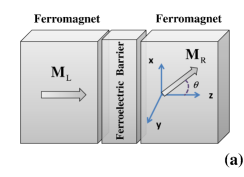
Nonetheless, metal-oxides barriers display a wide variety of functional properties among which ferroelectricity can be used to add a degree of freedom to the system multiferroics . In oxide perovskytes, such as BaTiO3, uncompensated charge screening in the material induces a ferroelectric polarization which produces in turn very narrow charge depletion regions at the interfaces, as illustrated in Fig. 1. Inserted between non-magnetic metallic electrodes, ferroelectric barriers are expected to result in large tunneling electroresistance effects (TER) esaki ; zhu2 ; bilc . The combination of ferroelectricity and ferromagnetism in a same material, referred to as a multiferroic, allows for the electric manipulation of the magnetization and vice-versa multiferroics . However, the difficulty of growing multiferroic thin films limits their exploitation as viable memory elements for now. A promising route is to use synthetic multiferroics, where a ferroelectric barrier is inserted between two ferromagnets. In this case, the system displays gigantic TER ratios tsymbal ; Gar1 ; Gar2 resulting from the impact of the ferroelectric polarization on interfacial spin polarization zhu2 ; burton ; int . Important progress have been realized recently and ferroelectric junctions have been implemented in solid-state memory devices chanth .
Whereas the above results are obtained for thick ferroelectric barriers ( nm), reducing the barrier thickness would enable spin transfer to occur. In the present Letter, we theoretically address the nature of the spin torque in magnetic tunnel junctions comprising such a thin ferroelectric barrier. We demonstrate that the sign and magnitude of the spin transfer torque and magnetoresistance can be controlled by tuning the ferroelectric polarization, opening new avenues for spin-based functional devices.
 |
 |
Let us consider a magnetic tunnel junction composed of FML/FEB/FMR, where FML(R) is the semi-infinite left (right) ferromagnetic electrode and FEB is a non-magnetic ferroelectric insulator, such as BaTiO3, PbTiO3, Pb(Zr0.2Ti0.8)O3, etc. The unit magnetization vectors are and , being the angle between the magnetization directions, see Fig. 1(a). The junction is treated within a 1-dimensional free-electron two-band Stoner model, following Refs. zhang, and zhu1, . The Hamiltonian of the full system reads , where
where
| (3) | |||||
| (4) |
is the screening length of the -th electrode, is the spin-dependent density of states with , is the thickness of the ferroelectric barrier, is the vector of the Pauli matrices, are the dielectric static permittivity of the vacuum and ferroelectric barrier, respectively. is the ferroelectric polarization, is the exchange energy, is the equilibrium spin density, , is Stoner exchange parameter, the hat denotes a 22 matrix in spin space.
The eigenstates of the full system are obtained by standard wave matching procedure and the resulting spin-dependent wave functions are expressed in terms of a combination of Airy (barrier) and Bessel (ferromagnets) functions. In this picture, the charge and spin currents are defined
| (5) | |||
| (6) |
referring to the imaginary part and being the Fermi-Dirac distribution function of the -th electrode. The spin transfer torque is defined as slonc96 , where is the volume of the ferromagnet. In the case of semi-infinite electrodes, it reduces to the interfacial tunneling spin current: , where and . For the numerical simulations, we choose the parameters describing Fe/BaTiO3/Fe symmetric MTJs (at low temperatures): the effective Fermi energy is EF=2.62 eV with an exchange splitting =3.86 eV corresponding to the majority (minority) Fermi wave vector =1.09 Å-1 (=0.4 Å-1) and eV. The barrier dielectric permittivity is =90 and its thickness is =1 nm. The barrier height and electron effective mass are taken as =0.6 eV and =0.28. These parameters, rather conservative, are extracted from ab-initio calculations and correspond to an effective decay wave vector of 2 nm-1 burton . The screening lengths were derived according to Eq.(4), =0.8 Å. The typical ferroelectric polarizations (FEP) highlighted in the literature are in the range of 10 to 75 Gar2 ; Petraru . The value of the FEP strongly depends on the ferroelectric layer thickness and interfacial structure Petraru ; burton ; int . Finally, in the present work, we only focus on the case of a symmetric tunnel junction composed of similar ferromagnetic electrodes.
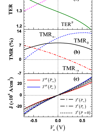
The interplay between tunnel electroresistance and spin transport has been predicted theoretically zhu1 ; burton ; zhu2 and demonstrated experimentally chanth ; Gar1 ; Gar2 , allowing for the ferroelectric control of the magnetoresistance and the magnetic control of the electroresistance. However, the influence of the ferroelectric polarization on the bias dependence of the tunneling magnetoresistance remains unexplored. In the remainder of this work, we define the TMR and TER as
| (7) | |||
| (8) |
denotes the tunneling charge current in parallel (P) and antiparallel (AP) configurations, and refers to the leftward (negative) or rightward (positive) ferroelectric polarization of the barrier. The bias dependence of the tunnel magneto- and electroresistance as well as the current-voltage characteristics are shown in Fig. 2(a)-(c). The TER evaluated for this symmetric MTJ is rather small : TER1.3 (30%) for P and TER1.4 (40%) for AP magnetic configurations [Fig. 2(a)]. Switching the magnetization configuration results in a strong asymmetric alteration of the bias dependence of the electroresistance effect. The most striking feature is obtained when analyzing the influence of the ferroelectric polarization on the TMR. In the absence of polarization [Fig. 2(b), black curve], the TMR is symmetric as expected in the case of a symmetric MTJ review_mtj . We note that the bias-induced TMR reversal occurs at large bias voltages (1 V, not shown). However, in the presence of ferroelectric polarization in the barrier, the potential profile becomes asymmetric and the bias dependence of the TMR is heavily distorted, yielding TMR sign reversal at small voltages. Asymmetric tunnel junctions are expected to generate much larger TER effects than symmetric ones zhu1 and therefore, one can expect much stronger distortion of the bias dependence of the TMR, depending on the FEP direction.
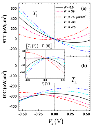
Let us now consider the spin transfer torque exerted on the right layer. Figure 3(a) and 3(b) display the bias dependence of the in-plane and out-of-plane components, respectively. In the absence of ferroelectricity (solid lines), the torque has the form and , as expected in the case of a symmetric tunnel junction Theo ; asym ; spindiode . In the presence of ferroelectric polarization, the bias dependence of both components is strongly rectified. The interlayer exchange coupling constant, defined as slonc96 ; Theo , decreases in absolute value for negative FEP and increases for positive one, in agreement with Ref. zhu2Cond, . Most importantly, we find that the spin torque efficiency (or torkance spindiode ), defined as , is dramatically affected by the presence of ferroelectric polarization (see Fig. 4). The non-equilibrium interlayer exchange coupling (or net spin torque) defined as acquires a positive (negative) efficiency for negative (positive) ferroelectric polarization for small biases (inset of Fig. 3). The in-plane torque efficiency is also rectified and can be even reversed at large FEP, as displayed in Fig. 3(a).
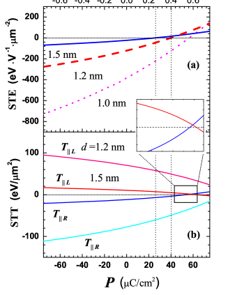
These results demonstrate the control of the spin torque efficiency by the ferroelectric polarization. In Fig. 4(a) the FEP-dependence of the in-plane torque efficiency is represented for different barrier thicknesses. The slope of the spin torque efficiency as a function of the FEP decreases at larger thickness, indicating that the ferroelectric control of the torkance is more effective in thin barriers. In other words, the difference in spin torque magnitude when switching the FEP is larger when decreasing the barrier thickness. On the other hand, the threshold FEP required to reverse the sign of the in-plane torque decreases with the barrier thickness.
These two behaviors can be interpreted by analyzing the asymmetric spin transport in the barrier. In the non-equilibrium transport formalism, the total spin torque exerted on the right ferromagnet arises from a balance between the torque contributions of the electrons originating from the left reservoir and those originating from the right reservoir [see Eq. (6)]. In the presence of ferroelectricity, the barrier becomes asymmetric and the tunneling rate of leftward and rightward electrons is no more equal, resulting in the TER zhu1 ; zhu2 . The contributions of the electrons originating from the left and right reservoirs to the in-plane torque as a function of the FEP are displayed in Fig. 4(b), for different barrier thicknesses. The slope of the spin torque as a function of the FEP is larger for thinner barriers, due to the larger amount of tunneling electrons experiencing the asymmetric tunneling. On the other hand, the TER effect is more effective for thicker barriers and the asymmetry in tunneling probability between leftward and rightward electrons is larger. This increased tunneling electroresistance results in a reversal of the sign of the in-plane torque at positive FEP.
The ferroelectric control of the bias dependence of both in-plane and out-of-plane components of the spin torque has important impacts in terms of current-driven magnetization switching and dynamics. It is usually accepted that in-plane torque drives the magnetization switching and self-sustained precessions Brataas ; Ralph . Therefore, a smart design of the ferroelectric junction enables the control of the dynamical properties by tuning both the injected current and ferroelectric polarization. Another interesting aspect is the control of the out-of-plane torque. In a recent publication, Oh et al. Oh demonstrated the important role of the out-of-plane component on current-driven magnetic instabilities (tagged switching back phenomenon) in MTJs. In light of the present study, controlling this effect through ferroelectricity seems a viable route to reduce these instabilities. Since the ferroelectric polarization is usually controlled through voltage pulses, spin torque and FEP switching can be combined to obtain original device operation modes.
Finally, two important aspects are to be considered regarding the applicability of the present theory to experimental situations. First, the TER obtained numerically with the present model (two band Stoner model in a symmetric junction) is small compared to the experimental observations: about 40% in the present work compared to 10,000% chanth and 75,000% Gar1 in thick BaTiO3. This indicates that the asymmetry expected experimentally is actually much larger than the one derived in the present work, which implies that the ferroelectric control of the spin torque efficiency is expected to be much larger. Second, whereas the voltage-control of tunneling electroresistance has been recently realized in thick BaTiO3-based MTJs Gar1 ; chanth , the realization of spin transfer torque in thin BaTiO3 junctions presents the advantage of generating unique current-driven dynamical states that are absent in thick ferroelectric junctions. The combination of ferroelectricity with spin transfer torque is thus expected to produce a wealth of original states of major interest for technologists and researchers.
We thank Prof. M. Zhuravlev and Dr. N. Useinov for useful conversations and support, and Prof. E.Y. Tsymbal for his critical review of the manuscript and his constructive comments.
References
- (1) C. Chappert, A. Fert, and F. Nguyen Van Dau, Nature Mater. 6, 813 (2007); J. A. Katine and E. E. Fullerton, J. Magn. Magn. Mater. 320, 1217 (2008).
- (2) A. Brataas, A. D. Kent, and H. Ohno, Nature Mater. 11, 372 (2012).
- (3) D. Ralph and M. Stiles, J. Magn. Magn. Mater. 320, 1190 (2008).
- (4) M. Tsoi, Handbook of Spin Transport and Magnetism, edited by E.-Y. Tsymbal and I. Zutic, Chap. 7 (CRC Press, Boca Raton, 2011); A. Manchon, and S. Zhang, in Handbook of Spin Transport and Magnetism, edited by E.-Y. Tsymbal and I. Zutic, Chap. 8 (CRC Press, Boca Raton, 2011).
- (5) T. Maruyama, Y. Shiota, T. Nozaki, K. Ohta, N. Toda, M. Mizuguchi, A. A. Tulapurkar, T. Shinjo, M. Shiraishi, S. Mizukami, Y. Ando and Y. Suzuki, Nature Nanotechnology, 4, 158 (2009); Y. Shiota, T. Nozaki, F. Bonell, S. Murakami, T. Shinjo and Y. Suzuki, Nature Materials 11, 39 (2012).
- (6) J. C. Slonczewski, J. Magn. Magn. Mater. 159 L1 (1996); L. Berger, Phys. Rev. B 54, 9353 (1996).
- (7) D. Houssameddine, U. Ebels, B. Delaet, B. Rodmacq, I. Firastrau, F. Ponthenier, M. Brunet, C. Thirion, J.-P. Michel, L. Prejbeanu-Buda, M.-C. Cyrille, O. Redon, B. Dieny, Nature Materials 6 447 (2007).
- (8) M. Hosomi, H. Yamagishi, T. Yamamoto, K. Bessho, Y. Higo, K. Yamane, H. Yamada, M. Shoji, H. Hachino, C. Fukumoto, H. Nagao, H. Kano, IEDM Techn. Digest 459 (2005); T. Kawahara, R. Takemura, K. Miura, J. Hayakawa, S. Ikeda, Y. Lee, R. Sasaki, Y. Goto, K. Ito, I. Meguro, F. Matsukura, H. Takahashi, H. Matsuoka, H. Ohno, ISSCC Digest 480 (2007).
- (9) S.S.P. Parkin, M. Hayashi and L. Thomas, Science 320, 190 (2008).
- (10) S.S.P. Parkin, C. Kaiser, A. Panchula, P. M. Rice, B. Hughes, M. Samant and S.-H. Yang, Nature Mater. 3, 862-867 (2004); S. Yuasa, T. Nagahama, A. Fukushima, Y. Suzuki, and K. Ando, Nature Mater. 3, 868-871 (2004).
- (11) F. Bonell, T. Hauet, S. Andrieu, F. Bertran, P. Le Fevre, L. Calmels, A. Tejeda, F. Montaigne, B. Warot-Fonrose, B. Belhadji, A. Nicolaou, and A. Taleb-Ibrahimi, Phys. Rev. Lett. 108, 176602 (2012).
- (12) See e.g. J.P. Velev, P.A. Dowben, E.Y. Tsymbal, S.J. Jenkins, and A.N. Caruso, Surf. Sc. Rep. 63, 400 (2008).
- (13) I. Theodonis, N. Kioussis, A. Kalitsov, et al., Phys. Rev. Let. 97, 237205 (2006); C. Heiliger and M. D. Stiles, Phys. Rev. Lett. 100, 186805 (2008); A. Manchon, N. Ryzhanova, A. Vedyayev, M. Chschiev, B. Deny, J.Phys.:Condens. Matter 20, 145208 (2008);
- (14) M. Wilczynski, J. Barnas and R. Swirkowicz, Phys. Rev. B 77, 054434 (2008); Y.-H. Tang, N. Kioussis, A. Kalitsov, W. H. Butler, and R. Car, Phys. Rev. Lett. 103, 057206 (2009); Phys. Rev. B 81, 054437 (2010); A. Manchon, S. Zhang, and K.-J. Lee, Phys. Rev. B 82, 174420 (2010).
- (15) Y. Huai et al. Appl. Phys. Lett. 84, 3118 (2004); G. D. Fuchs et al., Appl. Phys. Lett. 85, 1205 (2004).
- (16) J. C. Sankey, et al. Nature Phys. 4, 67 (2008); H. Kubota, et al. Nature Phys. 4, 37 (2008).
- (17) S.-C. Oh, S.-Y. Park, A. Manchon, M. Chshiev, J.-H. Han, H.-W. Lee, J.-E. Lee, K.-T. Nam, Y. Jo, Y.-C. Kong, B. Dieny and K.-J. Lee, Nature Physics 5, 898-902 (2009).
- (18) A Manchon, R. Matsumoto, H. Jaffres, and J. Grollier, Phys. Rev B 86, 060404(R) (2012).
- (19) W. Eerenstein, N. D. Mathur and J. F. Scott Nature 442, 759 (2006); H. Bea, M. Gajek, M. Bibes and A. Barthélémy, J. Phys.: Condens. Matter 20, 434221 (2008).
- (20) L. Esaki, R. B. Laibowitz, P. J. Stiles, IBM Tech. Discl. Bull. 13, 2161 (1971).
- (21) M. Ye. Zhuravlev, R. F. Sabirianov, S. S. Jaswal, E.Y. Tsymbal, Phys. Rev. Lett. 94, 246802 (2005); M. Ye. Zhuravlev, S. S. Jaswal, E. Y. Tsymbal, R. F. Sabirianov, Appl. Phys. Lett. 87, 222114 (2005).
- (22) D. I. Bilc, F. D. Novaes, J. Iniguez, P. Ordejon, and P. Ghosez, ACS Nano 6, 1473 (2012).
- (23) E. Tsymbal and H. Kohlstedt, Science 313, 181 (2006).
- (24) V. Garcia, S. Fusil, K. Bouzehouane, S. Enouz-Vedrenne, N. D. Mathur, A. Barthélémy, M. Bibes, Nature 460, 81-84 (2009).
- (25) V. Garcia, M. Bibes, L. Bocher, et al., Science 327, 1106 (2010); D. Pantel, S. Goetze, D. Hesse and M. Alexe, Nature Mater. 11, 289-293 (2012).
- (26) J. P. Velev, Ch.-G. Duan, J. D. Burton, A. Smogunov, M. K. Niranjan, E. Tosatti, S. S. Jaswal, E. Y. Tsymbal, Nano Letters 9, 427-432 (2009); J. Velev, C.-G. Duan, K. D. Belashchenko, S. S. Jaswal, and E.Y. Tsymbal, Phys. Rev. Lett. 98, 137201 (2007); J. D. Burton and E.Y. Tsymbal, Phys. Rev. Lett. 106, 157203 (2011).
- (27) S. Valencia, A. Crassous, L. Bocher, V. Garcia, X. Moya, R. O. Cherifi, C. Deranlot, K. Bouzehouane, S. Fusil, A. Zobelli, A. Gloter, N.D. Mathur, A.Gaupp, R. Abrudan, F. Radu, A. Barthélémy and M. Bibes, Nature Materials 10, 753 (2011); L. Bocher, A. Gloter, A. Crassous, V. Garcia, K. March, A. Zobelli, S. Valencia, S. Enouz-Vedrenne, X. Moya, N. D. Marthur , C. Deranlot, S. Fusil, K. Bouzehouane, M. Bibes, A. Barthélémy, C. Colliex, and O. Stephan, Nano Lett. 12, 376 (2012).
- (28) A. Chanthbouala, A. Crassous, V. Garcia, et al., Nature Nanotechnology 7, 101 -104 (2012); A. Chanthbouala, V. Garcia, R. O. Cherifi, et al., Nature Materials 11, 860 (2012).
- (29) S. Zhang, Phys. Rev. Lett. 83, 640 (1999).
- (30) M. Y. Zhuravlev, S. Maekawa, E. Y. Tsymbal, Phys. Rev. B 81, 104419 (2010).
- (31) A. Petraru, N.A. Pertsev, H. Kohlstedt, U. Poppe, R. Waser, A. Solbach and U. Klemradt, J. Appl. Phys. 101, 114106 (2007); L. Pintilie, I. Boerasu, M. J. M. Gomes, T. Zhao, R. Ramesh, M. Alexe, J. Appl. Phys.98, 124104 (2005).
- (32) E. Y. Tsymbal, O. N. Mryasov and P. R. LeClair, J. Phys.: Condens. Matter 15 R109 (2003).
- (33) M. Zhuravlev, A. Vedyayev and E. Tsymbal, J. Phys.: Condens. Matter 22, 352203 (2010).