Fast acoustic tweezers for the two-dimensional manipulation of individual particles in microfluidic channels
Abstract
This paper presents a microfluidic device that implements standing surface acoustic waves in order to handle single cells, droplets and generally particles. The particles are moved in a very controlled manner by the two-dimensional drifting of a standing wave array, using a slight frequency modulation of two ultrasound emitters around their resonance. These acoustic tweezers allow any type of motion at velocities up to few 10 mm/s while the device transparency is adapted for optical studies. The possibility of automation provides a critical step in the development of lab-on-a-chip cell sorters and it should find applications in biology, chemistry and engineering domains.
The recent progresses in lab on chip technologies have opened numerous possibilities for medical diagnosis and biological tests. One issue is the adaptation of current technologies to microscale for higher integration, cost reduction and parallel processing capabilities, as illustrated by the efforts to develop micro fluorescent activated cell sorters (FACS) Fu et al. (1999); Franke et al. (2010). Another issue is the manipulation of individual cells for in situ diagnostics and optical characterization. Surface acoustic wave (SAW) techniques are particularly promising for particle handling as they allow, when combined with a polydimethylsiloxane (PDMS) microfluidic channel, optical access, local actuation and fast response time capabilities.
In this Letter, we describe a device that can move particles down to the size of cells and precisely control their positions in a two-dimensional (2D) acoustic cage. We show that the characteristics of these acoustic tweezers are to be fast (10 mm/s) and to exert forces that are strong enough to counteract friction from wall, or drag from hydrodynamic flows of reasonable velocities. We present measurements of the particle trajectories obtained for an oscillatory driving motion, so as to understand the dynamics of slippage from the acoustic trap above a threshold velocity. Last, we propose an insight into the forces acting on particles in a microchannel under the action of SAW emission, providing evidence of their 3D action.
Friend et al. Friend and Yeo (2011) have recently drawn a full panorama of the potential offered by acoustic microfluidics based on SAW emission in the case of standing waves (SSAW), propagating waves (PSAW) or both. Using PSAW, Franke et al. have demonstrated the deviation of a continuous flow containing cells at high frequency Franke et al. (2010), and of droplets in a water in oil emulsion Franke et al. (2009). Note that when using these pushing forces the final position is not directly controlled because it depends on the surrounding fluid velocity. Using SSAW, Shi et al. were able to force bovine red blood cells particles to form lines Shi et al. (2008) and obtained point-wise concentrations Shi et al. (2009) of latex beads and E. Coli cells with two interdigitated transducers (IDTs) in an orthogonal arrangement. In this case, it is believed that the observed patterns result from acoustic forces due to SAW leakage in the liquid. These forces pushing the particle towards the pressure nodes, this leads to a situation analog to bulk acoustic wave experiments Manneberg et al. (2009); Wiklund and Hertz (2006). Wood et al. have also shown line wise Wood et al. (2008) and point wise Wood et al. (2009) alignments of latex particles using opposite pairs of IDTs, the visualization of particles being obtained through a glass superstrate. In contrast with these experiments where the particles cannot be moved at will on predetermined locations, Meng et al. Meng et al. (2011) have described a device where micro-bubbles and breast cancers cells can be transported at will across the width of a microfluidic channel. The major improvement is the use of some phase shift between the two IDTs located on both part of to microfluidic channel to move the standing wave pattern, and hence the particles. Recently Ding et al. Ding et al. (2012) have proposed to implement chirped electrodes with a broadband response (in between 18.5 MHz and 37 MHz) to change the wavelength of a 2D standing wave pattern in both directions, and thus entrain particles.
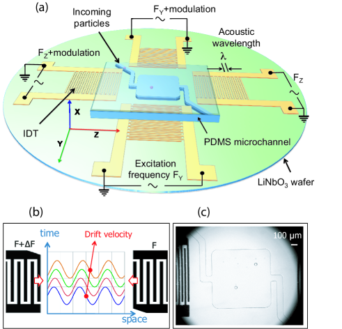
In the present work, we have designed a device that cumulates the advantages of a 2D standing wave pattern to trap particles in some nodal positions and the continuous control of a small phase shift to displace them, staying at the resonance frequency of the device. The experimental setup is schematized on figure 1. The piezoelectric is a 2”, 500 m thick LiNbO3 single crystal wafer, with X-cut section and Z as the main propagation direction ( = 5.9% in Z direction, and 3.1% in Y direction Renaudin et al. (2009)). Electrodes forming the IDTs are produced by successive metal depositions (Ti/Au, 15 nm/100 nm) on the LiNbO3 wafer with a standard lift-off process. They comprise 40 fingers electrode pairs with a constant pitch of 100 m. The microfluidic channel, 50 m deep, is fabricated in PDMS with soft-lithography using mold-replica techniques. It contains a flow focusing geometry Dollet et al. (2008) used to produce droplets, a main channel and a side branch 100 m wide leading to the main acoustic chamber 1 mm1 mm. As the flow exerts an extra force on the particles to be counterbalanced by the IDT emission, it is aligned along Z. The channel is assembled under microscope on the piezoelectric wafer, after it has been exposed for 10 s to an ozone plasma to promote adhesion between PDMS and LiNbO3Haubert et al. (2006). The whole setup is heated to 65°C for two hours and clamped between plexiglas plates and two aluminum disks to avoid the premature detachment of the channel. Visualization is made using a standard microscope (Macroscope Leica Z6) and particle trajectories are recorded using a fast camera (Phantom Miro 4, Vision Research) and treated using ImageJ software (NIH, Bethesda, MD).
Two categories of particles are presented to illustrate the efficiency of the tweezers: oil in water droplets, and human red and white blood cells (hRBCs and hWBCs). The oil droplets are generated in situ by injecting 50 cSt silicone oil (Sigma Aldrich) and de-ionized water with 10% dishwashing surfactant (Dreft, Procter and Gamble) in the flow focus Garstecki et al. (2004). The cells are obtained by successive concentrations using centrifugation and dilution in a buffer solution (PBS) for plasma removing. The IDTs are excited by a set of arbitrary waveform generators each connected to 40 or 50 dB amplifiers (Amplifier Research, model 75A250A and ENI, Models 320L, 325LA, 411LA). A calibration of the performance of each IDT as a function of frequency is initially performed by observing the deviation of some particles. The maxima are found at frequencies in the range 34.537 MHz as expected from the ratio between the velocity of the Rayleigh wave of the water loaded LiNbO3 to the IDT pitch Campbell and Jones (1970). A 1D or 2D standing wave pattern is created by exciting the IDT pairs at the same frequency and amplitude, for which the two counter-propagating waves compensate.
Particle motion is achieved by the low frequency modulation of one IDT respective to its opposite. Periodic trajectories were obtained by using modulations of the form where represents some frequency deviation and the modulation frequency in the periodic function . Note that (of the order of Hz) is much smaller than , so that the device stays at resonance. This type of excitation automatically creates a dynamic phase shift with respect to the other electrode such that and thus a drift of the interference pattern at the velocity . This contrasts with other works Meng et al. (2011) where the motion was obtained by the progressive adjustment of the static relative phase between the two IDTs, or by an important modification of the frequency of both electrodes to change the wavelength Ding et al. (2012).
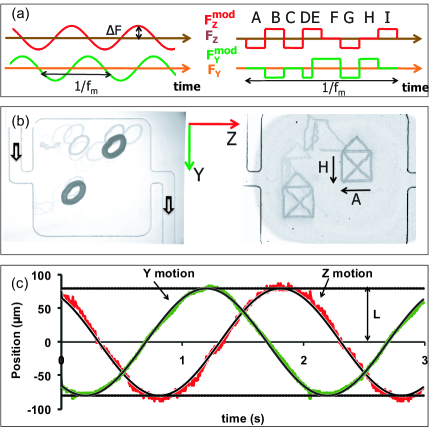
Figure 2 illustrates the results obtained with oil droplets that move under the action of two sine function modulations along the two directions Y and Z (see also Supplementary MaterialNot ). The various droplets, differing by their diameters (40 m and 10 m for the smallest) follow identical elliptical trajectories corresponding to Lissajous patterns. As a function of time, a very good fit is obtained from the following parameter free model: and with half the amplitude of the course and some initial phase at the starting time of the SAW actuation. The figure also shows the trajectories of WBCs (diam. m) with a modulation function programmed to describe a ‘house’ shape. The control is still good, though some discrepancies can be seen. For RBCs, which sizes are smaller (68 m), the control gets more difficult at higher velocities and may depend on the remaining flow direction.
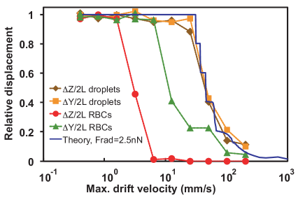
In order to determine the limit velocities at which particles can be moved, the distances traveled by the particles along (and transverse to) the main flow have been plotted in figure 3 as a function of the typical drift velocity for the sinusoidal modulation. Up to 25 mm/s, oil droplets have positions exactly predictable showing that the two degrees of freedom are independent. At larger velocities, the drifting amplitude is damped, since the viscous forces become comparable to the acoustic ones. For RBCs, this maximum obtained velocity reaches 7 mm/s in the flow transverse direction and is reduced to 1.5 mm/s along the main flow.
The motion of the object can be predicted from the balance of forces at low Reynolds number:
| (1) |
where the first term is the radiation force on a object located at the position in a standing wave (in the Y or Z direction) whose nodes move according to the position , and where the second term is the Stokes drag at velocity in a fluid of viscosity . The time integration of gives an amplitude of displacement very close to that of figure 3, with a sharp drop in displacement efficiency when the drifting velocity exceeds , provided the radiation force is fitted by nN for the m droplets (and nN and 0.6 nN along the Z and Y direction for the RBCs, assuming a diameter of 8 m). We can predict the acoustic pressure associated with theses forces to be Pa ( and Pa for RBCs in Z and Y directions). These values for the pressures are obtained using the expression by Yosioka Yosioka and Kawasima (1955) for the radiation force as a function of acoustic pressure: , with and a parameter that depends on the acoustic properties of objects and water Not . These predictions are of the order of magnitude expected for nanometric vibrations amplitudes of the substrate Shilton et al. (2008) (as can be computed using , with the density of water, the sound velocity, the vibration amplitude and the pulsation).
In an attempt to identify the parameters that influence the efficiency of the tweezers, we multiplied the experiments by varying particle sizes, particle composition, flow velocities, SAW amplitude and direction of emission. We observed that the proximity of the lateral channel walls (seen on Fig. 2(b)) could interfere with the particles motion due to undesired standing waves, that originate from the reflexion of the incoming waves and that are fixed respective to the moving standing wave pattern. It was also found that the acoustic threshold necessary to initiate motion depended both on the particle size and its composition. For a given size, the threshold is less for bubbles than for droplets, itself less than for cells. When the composition is fixed, the manipulation of smaller particles requires larger acoustic amplitudes. These observations are compatible with a mechanism where the forces at the origin of the acoustic tweezers are given by the gradient of acoustic pressure Yosioka and Kawasima (1955). However, some excessive acoustic amplitudes can also result in a decrease of the particle mobility as we now discuss.
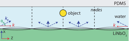
As sketched on figure 4, the creation of a standing wave from two counter propagating waves on the piezoelectric wafer also gives rise to a propagative component normal to the piezoelectric surface, which pushes the particles toward the PDMS walls. For objects whose dimensions exceed the channel height (large bubbles or droplets), this results in an increase of the friction forces at large acoustic powers. Dewetting of the thin film in between the object and the PDMS top surface can even be observed for objects at rest, when the disjoining pressure is not large enough to counterbalance the acoustic forces. For objects smaller than the gap height the mobility is also decreased, to an extent that depends on the top wall proximity and therefore on the amplitude of the radiation forces. This idea was verified by directly observing under a microscope the accumulation of RBCs against the PDMS. As a consequence, the search of an optimal acoustic power to manipulate particles with SAW involves the consideration of the 3D nature of the forces that are created.
In conclusion, we have developed and characterized acoustic tweezers that induce fast motion and precise positioning of single particles made of various materials. We found that the action of the SSAW also involves normal radiative forces, and we have evidenced their effect on the particle mobility. Eventually, we hope this work will contribute to the rapid development of efficient acoustic tweezers for cell manipulations, since it helps to adjust the amplitude of the acoustic force necessary to trap particles, depending on the desired drifting velocity.
The authors gratefully acknowledge financial support from ANR Microacoustics Grant ANR-08-JCJC-014-01.
References
- Fu et al. (1999) A. Y. Fu, C. Spence, A. Scherer, F. H. Arnold and S. R. Quake, Nat Biotech, 1999, 17, 1109–1111.
- Franke et al. (2010) T. Franke, S. Braunmuller, L. Schmid, A. Wixforth and D. A. Weitz, Lab Chip, 2010, 10, 789–794.
- Friend and Yeo (2011) J. Friend and L. Y. Yeo, Rev. Mod. Phys., 2011, 83, 647–704.
- Franke et al. (2009) T. Franke, A. R. Abate, D. A. Weitz and A. Wixforth, Lab Chip, 2009, 9, 2625.
- Shi et al. (2008) J. Shi, X. Mao, D. Ahmed, A. Colletti and T. J. Huang, Lab on a Chip, 2008, 8, 221–223.
- Shi et al. (2009) J. Shi, D. Ahmed, X. Mao, S.-C. S. Lin, A. Lawit and T. J. Huang, Lab Chip, 2009, 9, 2890–2895.
- Manneberg et al. (2009) O. Manneberg, B. Vanherberghen, B. Onfelt and M. Wiklund, Lab Chip, 2009, 9, 833–837.
- Wiklund and Hertz (2006) M. Wiklund and H. M. Hertz, Lab Chip, 2006, 6, 1279–1292.
- Wood et al. (2008) C. D. Wood, S. D. Evans, J. E. Cunningham, R. O’Rorke, C. Wälti and A. G. Davies, Applied Physics Letters, 2008, 92, 044104.
- Wood et al. (2009) C. D. Wood, J. E. Cunningham, R. O’Rorke, C. Wälti, E. H. Linfield, A. G. Davies and S. D. Evans, Applied Physics Letters, 2009, 94, 054101.
- Meng et al. (2011) L. Meng, F. Cai, Z. Zhang, L. Niu, Q. Jin, F. Yan, J. Wu, Z. Wang and H. Zheng, Biomicrofluidics, 2011, 5, 044104.
- Ding et al. (2012) X. Ding, S.-C. S. Lin, B. Kiraly, H. Yue, S. Li, I.-K. Chiang, J. Shi, S. J. Benkovic and T. J. Huang, Proceedings of the National Academy of Sciences, 2012, 109, 11105–11109.
- Renaudin et al. (2009) A. Renaudin, J.-P. Sozanski, B. Verbeke, V. Zhang, P. Tabourier and C. Druon, Sensors and Actuators B: Chemical, 2009, 138, 374–382.
- Dollet et al. (2008) B. Dollet, W. van Hoeve, J.-P. Raven, P. Marmottant and M. Versluis, Phys. Rev. Lett., 2008, 100, 034504–4.
- Haubert et al. (2006) K. Haubert, T. Drier and D. Beebe, Lab Chip, 2006, 6, 1548–1549.
- Garstecki et al. (2004) P. Garstecki, I. Gitlin, W. DiLuzio, G. M. Whitesides, E. Kumacheva and H. A. Stone, Appl. Phys. Lett., 2004, 85, 2649–2651.
- Campbell and Jones (1970) J. J. Campbell and W. R. Jones, Journal of Applied Physics, 1970, 41, 2796–2801.
- (18) Supplementary material available at http://?? with 4 movies illustrating the acoustic manipulation of droplets and biological cells in the microfluidic chamber.
- Yosioka and Kawasima (1955) K. Yosioka and Y. Kawasima, Acustica, 1955, 5, 167.
- (20) , where the density and speed of sound within the object are respectively 970 kg/m3 and 997 m/s for silicone oil Bertin (2011), or 1099 kg/m3 and 1646 m/s for RBCs in isotonic solution Weiser and Apfel (1982), taking for water = 1000 kg/m3 and = 1500 m/s.
- Shilton et al. (2008) R. Shilton, M. K. Tan, L. Y. Yeo and J. R. Friend, Journal of Applied Physics, 2008, 104, 014910.
- Bertin (2011) N. Bertin, Ph.D. thesis, Université Bordeaux I, 2011.
- Weiser and Apfel (1982) M. A. H. Weiser and R. E. Apfel, The Journal of the Acoustical Society of America, 1982, 71, 1261–1268.