Adjustable subwavelength localization in a hybrid plasmonic waveguide
Abstract
The hybrid plasmonic waveguide consists of a high-permittivity dielectric nanofiber embedded in a low-permittivity dielectric near a metal surface. This architecture is considered as one of the most perspective candidates for long-range subwavelength guiding. We present qualitative analysis and numerical results which reveal advantages of the special waveguide design when dielectric constant of the cylinder is greater than the absolute value of the dielectric constant of the metal. In this case the arbitrary subwavelength mode size can be achieved by controlling the gap width. Our qualitative analysis is based on consideration of sandwich-like conductor-gap-dielectric system. The numerical solution is obtained by expansion of the hybrid plasmonic mode over single cylinder modes and the surface plasmon-polariton modes of the metal screen and matching the boundary conditions.
I Introduction
The creation of the waveguides capable of guiding light with deep subwavelength confinement is of great interest for practical applications. These devices may throw open the doors to nanoscale optical communications, quantum computing, nanoscale lasers and bio-medical sensing. The main problem on the way to practical realization is the diffraction limit of light in dielectric media. Electromagnetic energy cannot be localized into nanoscale region much smaller than the wavelength of light in the dielectric Born_1999_book . The possible solution to this problem is using of the materials with negative dielectric permittivity. For example, metals are known to exhibit this property below the plasma frequency. Metal structures provide guiding of the surface plasmon-polaritons (SPP), which can be strongly localized near metal-dielectric interfacesGramotnev_2010_NaturePhot . However the propagation length of the strongly confined plasmonic modes is not large enough due to the presence of Ohmic losses in the dissipative metal regions.
The new approach for this challenge integrates dielectric waveguide with plasmonic one. The hybrid plasmonic waveguide consists of a high-permittivity dielectric nanofiber separated from a metal screen by low-permittivity dielectric nanoscale gap XiangZhang_2008_NaturePhot . Both the single fiber and the silver-dielectric interface cannot provide strong mode confinement at optical and near infrared frequencies, but such hybrid conductor-gap-dielectric architecture has experimentally demonstrated deep subwavelength optical waveguiding XiangZhang_2011_NatureComm . Relatively large propagation distance has been achieved due to low loss tangent at the operating frequency and the specific spatial structure of the guiding mode with field confinement within non dissipative gap region.
In the present paper we show that the hybrid plasmon polariton(HPP) mode confinement can be considerably risen by a specific choice of the materials, when the dielectric constant of the cylinder is greater than the absolute value of the dielectric constant of the metal screen. The main advantage of the choice is the hyperbolic-like dependence of the effective index on the gap width. This feature allows to achieve arbitrary subwavelength mode size at any frequency by tuning the distance between the cylinder and the metal. To justify our approach we theoretically investigate propagation of the HPP-mode. First we give qualitative analysis basing on the consideration of plane sandwich-like conductor-gap-dielectric waveguide structure(CGD) Avrutsky_2010_OptExpress . We derive exact analytical expression for effective index of the fundamental CGD-mode and give criterion when the HPP-mode is CGD-like. Finally, we present semi-analytical approach for describing of the HPP-mode propagation. Similar approach has been previously applied for plane wave scattering by a cylinder placed near the plane surface Frezza_1996 -Frezza_1997 .
The scheme is based on expansion of the HPP-mode over single cylinder modes and the surface plasmon polariton modes of the metal-dielectric interface and matching the boundary conditions for electromagnetic field components. Numerically obtained dispersion relations confirm the advantages of our design of the hybrid waveguide.
II Qualitative description
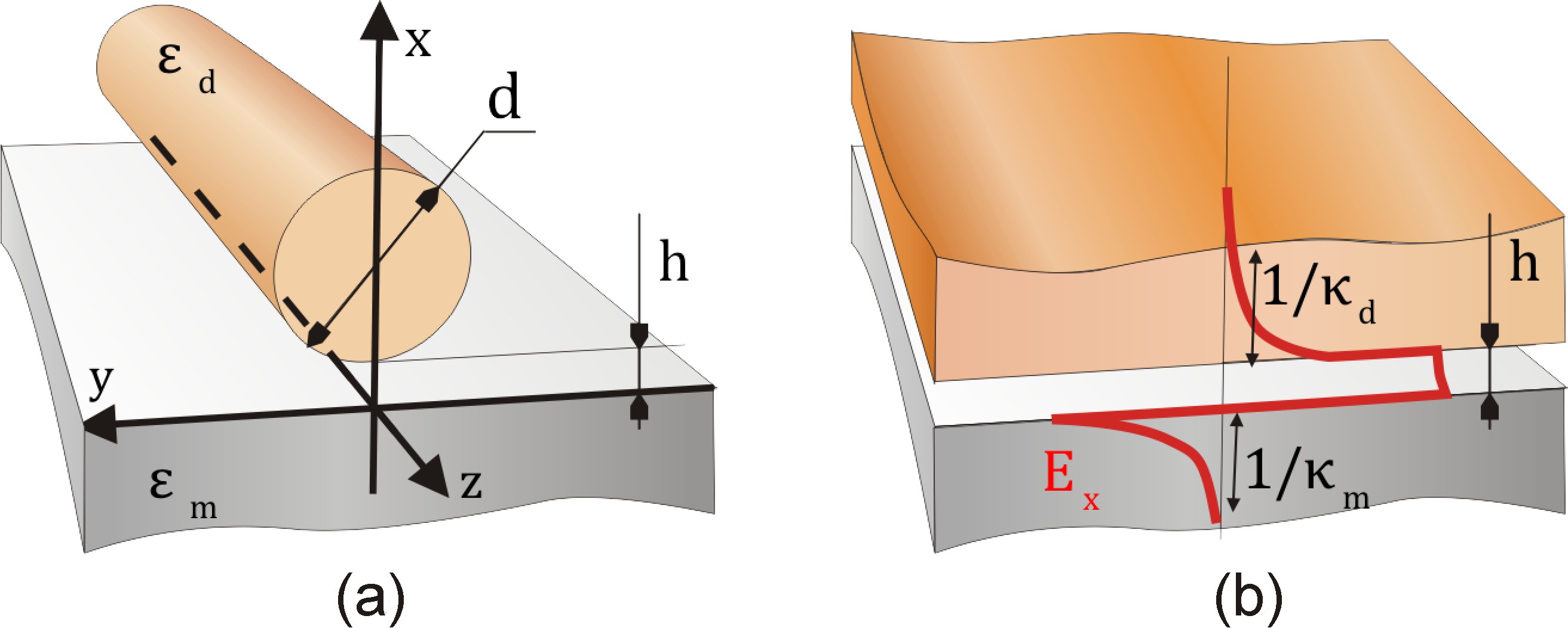
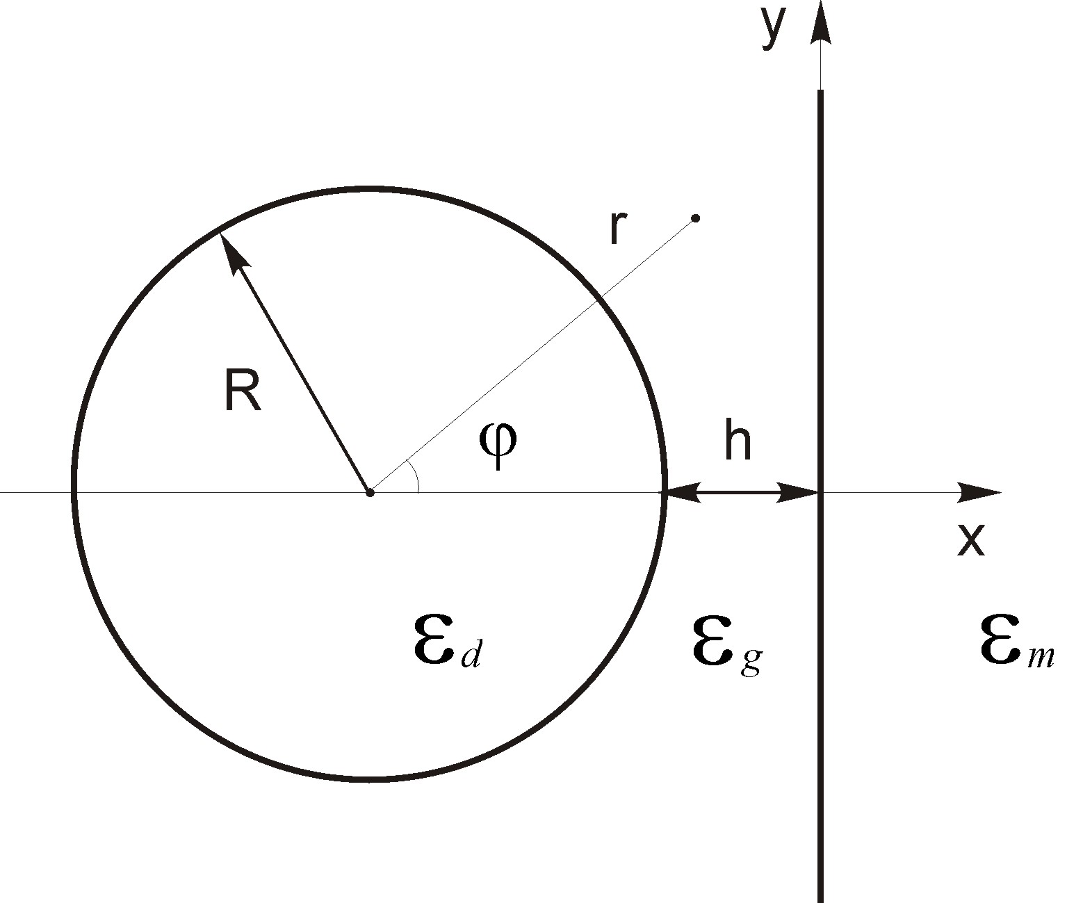
The geometry of the hybrid waveguide is the following: a circular dielectric cylinder of diameter and permittivity is placed above a metal screen of permittivity . The width of the gap between the cylinder and the metal screen is , see Fig. 1. Let us choose the Cartesian reference system as it is shown in Fig. 1: -axis is directed along the waveguide, whereas -axis is directed normally to the metal screen. We consider a plasmon-polariton mode of frequency and the propagation constant propagating along -axis. Thus, all electromagnetic field components depend on time and -coordinate as . We assume, that responses of both dielectric and metal on electromagnetic field are described by dielectric constants, which are and respectively. Generally, the outer medium may be not vacuum, but some dielectric medium having dielectric constant being equal to . All the materials are assumed to be nonmagnetic. To describe the mode confinement, it is convenient to introduce effective refractive index , which is defined as , where in the wavenumber in vacuum. The effective index determines the field penetration depth into the material with permittivity as . The penetration depth of the bound mode should be real in the unbounded waveguide constituents (metal and outer dielectric space), and may be imaginary for bounded constituents (fiber). The greater is the stronger degree of confinement.
Optimization for transversal field confinement implemented in paper XiangZhang_2008_NaturePhot for hybrid waveguide shows that the thinner gaps provide higher localization. The fiber diameter is much greater than the the gap width in the case, and the mode is sufficiently localized in the region where the gap can be considered as approximately plain. In the region, the waveguide shape is close to plain sandwich like conductor-gap-dielectric (CGD) structure, see Fig. 1. The limit of plain CGD-model was considered in Avrutsky_2010_OptExpress , where the properties of the bound fundamental mode were investigated. One of the main advantage of the CGD-mode is that effective index of the mode is greater than the refractive index of the dielectric , . This implies, that the electromagnetic field of the mode decays exponentially into the dielectric cladding. Nevertheless, the analysis proposed in Avrutsky_2010_OptExpress is not applicable to HPP-mode of hybrid waveguide with optimal diameter found in XiangZhang_2008_NaturePhot . The reason is that the mode of plain CGD-model indeed describes the HPP-mode only for large enough fiber diameter otherwise HPP-mode should be considered as a result of hybridization of surface plasmon polariton modes and the modes of the single dielectric cylinder.
| (1) |
The main goal of the present work is to give the theoretical description of the hybrid waveguide and to find approaches to deeper localization of the HPP-mode. Comparative analysis of XiangZhang_2008_NaturePhot ; Avrutsky_2010_OptExpress suggests, that in order to get stronger transversal miniaturization of the hybrid waveguide the CGD-like regime of propagation (with ) should be achieved for the diameter which is much less than free space wavelength. Our analysis of the plain CGD-structure shows that the localization of the fundamental mode can be significantly risen for special set of materials, when absolute value of the metal dielectric constant is less than the dielectric constant of the dielectric cladding, . For the case, the effective refractive index is proportional to inverse width of the gap, , when the width is small enough. To use the same effect for the hybrid waveguide, the cylinder diameter should sufficiently exceed some critical value , which is determined by the condition that the transversal size of the plain part of the gap is comparable with the mode penetration depth into the dielectric . The size of the plain part of the gap is evaluated as 2, thus the condition is . For greater enough than the guiding mode can approach the strongly confined mode of the sandwich like system even if the diameter of the cylinder is much less than free space wavelength.
In order to give general physical argumentation of our results let us consider planar sandwich-like CGD-waveguide in detail. The wave vector of fundamental CGD-mode (which is TM-mode) can be calculated from equation Avrutsky_2010_OptExpress
| (2) |
where for each material, and is the effective index of the mode. In particular, and are the penetration depths into the dielectric and the metal correspondingly. It is known that such plane three-layer waveguide supports the propagation of the bound eigen mode only if the width of the intermediate layer is less than some cut-off value which is determined by the permittivities at given frequency
When the thickness exceeds this critical value the fundamental CGD-mode becomes radiative with energy leaking into upper dielectric half space.
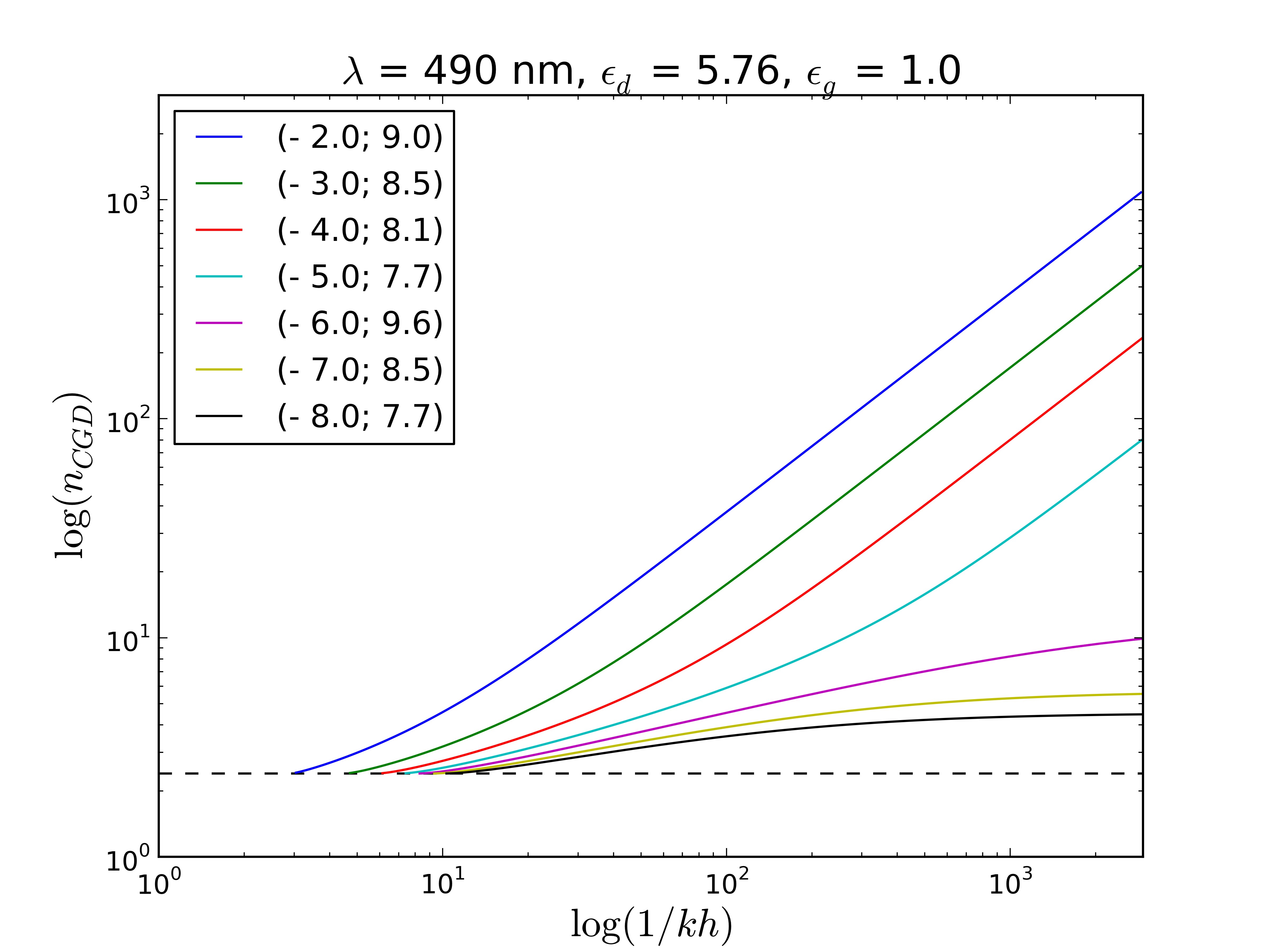
There is a significant difference between the dependence of the effective index on the gap thickness for the cases of low and high index dielectric, see Fig.2. For relatively low refractive index of dielectric, , there exists surface plasmon-polariton mode when the gap is absent, . It has effective index . Then the effective index of the fundamental CGD-mode is bounded, . Just the case was considered in the papers Avrutsky_2010_OptExpress and XiangZhang_2008_NaturePhot . Otherwise when permittivity of dielectric is relatively high
| (3) |
the effective index unlimitedly diverges as the gap thickness tends to zero, :
| (4) |
This leads to extremely strong light confinement in a transparent dielectric gap layer located between the high-index dielectric and the conductor. The actual degree of localization is restricted only by additional factors, such as increasing Ohmic losses in the metal, spatial dispersion and atomic structure of the materials. In this respect the properties of the conductor-gap-dielectric plasmonic mode similar to that of the gap plasmon polaritons in a conductor-gap-conductor structure Tanaka_2003 -Avrutsky_2007 . This feature is the principle behind our idea: in practice one should choose the metal of the absolute permittivity less than the permittivity of the cylinder and place cylinder at distance from the metal plane. When such metal is involved the effective index of the HPP mode can be significantly greater than effective index of electromagnetic field in bulk material of the cylinder even for very small diameters of the cylinder. Note, that to calculate group velocity and chromatic dispersion for the mode using the formula (4), one should know the dispersion laws for permittivities and . For thin gap , the group velocity scales as . Thus divergence of the CGD-mode effective index with gap width decreasing leads to strong reduction of the group velocity.
There is reverse side of the strong localization which is small propagation distance. It was shown in paper XiangZhang_2008_NaturePhot that the strongest localization of the HPP-mode corresponds to the lowest propagation length. It is common place of waveguides which use metal as a constructive component. Let us consider limit when the gap index is low, so . For the case
| (5) |
where is the imaginary part of the metal permittivity. It follows from Eq. (5), that the localization radius is of the order of in the limit . Note, that our approach allows to squeeze the mode at arbitrary frequency into any subwavelength scale simply by tuning the gap width in accordance with (4). Hence, our waveguide design breaks connection between mode localization and the carrying frequency of the mode. In particular, the approach may be interesting for design waveguides at THz frequencies XZhang_2009_PRL ; Nam_2009_OptExp . The propagation length i.e. reduces with the mode size reduction. To keep the propagation length acceptable for practical implementation at fixed degree of localization one should minimize loss tangent . Thus, a prospecting like Boltasseva_2008_Metamaterials is needed to propose the optimal choice of materials for our approach (3).
III Semi-analytical description
In the section, we present the semi-analytical approach to the propagation of the HPP-mode and discuss the numerical results. It follows from Maxwell’s equations that the electromagnetic field of guiding mode can be fully described by -components of the electric and the magnetic fields, and Marcuse_1972_eng . These fields satisfy the following two-dimensional Helmholtz differential equation inside the homogeneous areas where permittivity is constant:
| (6) |
where and is the free space wavenumber. The boundary conditions on the both interfaces are continuity of components , , and , where -component of a vector is its normal component.
Our semi-analytical method is based on the representation of the hybrid waveguide as an integration of the dielectric fiber and plane plasmonic waveguide. We express the electromagnetic field of the HPP-mode as a linear combination of cylindrical modes around the fiber and evanescent plane waves above the metal screen. Boundary conditions provide the system of linear equations on the expansion coefficients. Such an approach leads to highly efficient method of numerical solving a difficult boundary-value problems that describe the propagation of waves in a complex systems Bulushev_1988 -Zakowicz_1997_JOSAA . The scheme is developed in detail in Appendix A.
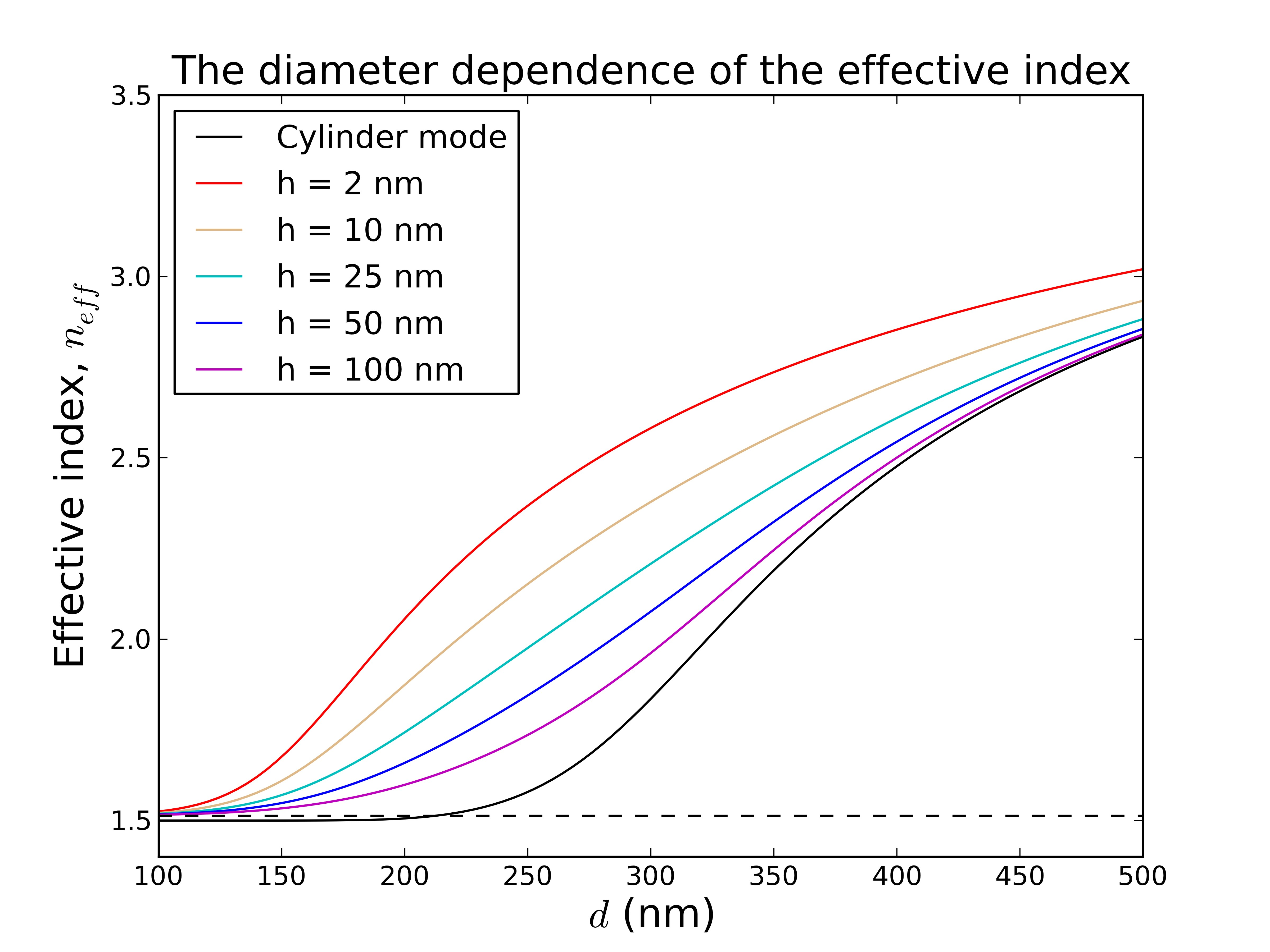
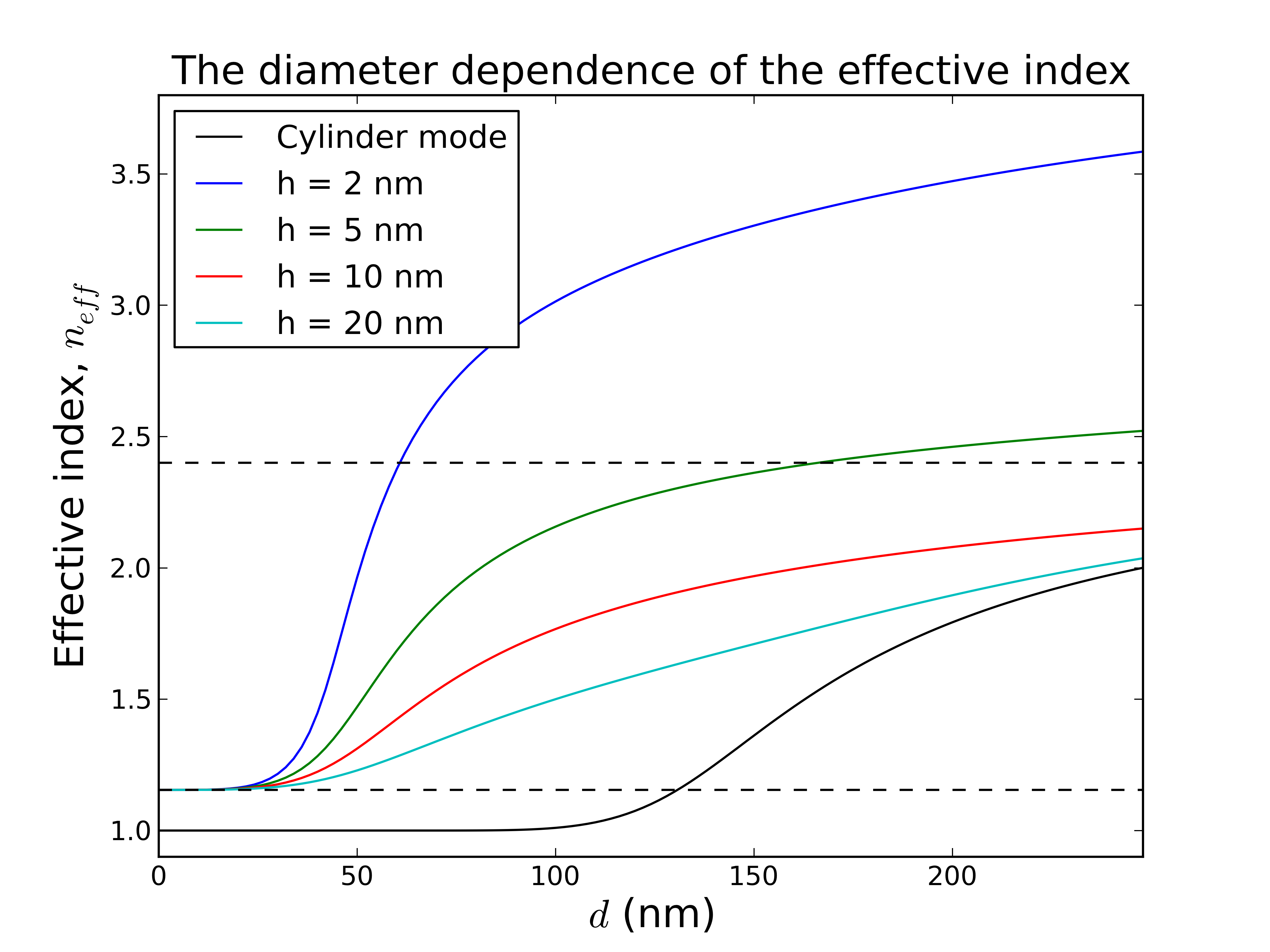
To verify our semi-analytical method, in Fig. 3 we present the dependence of the effective index of the fundamental hybrid mode on the cylinder diameter for a range of the gap widths in the case of telecommunication wavelength when . These dispersion curves are obtained from our numerical procedure and show a good agreement with the results obtained in XiangZhang_2008_NaturePhot by using finite-element package FEMLab from COMSOL.
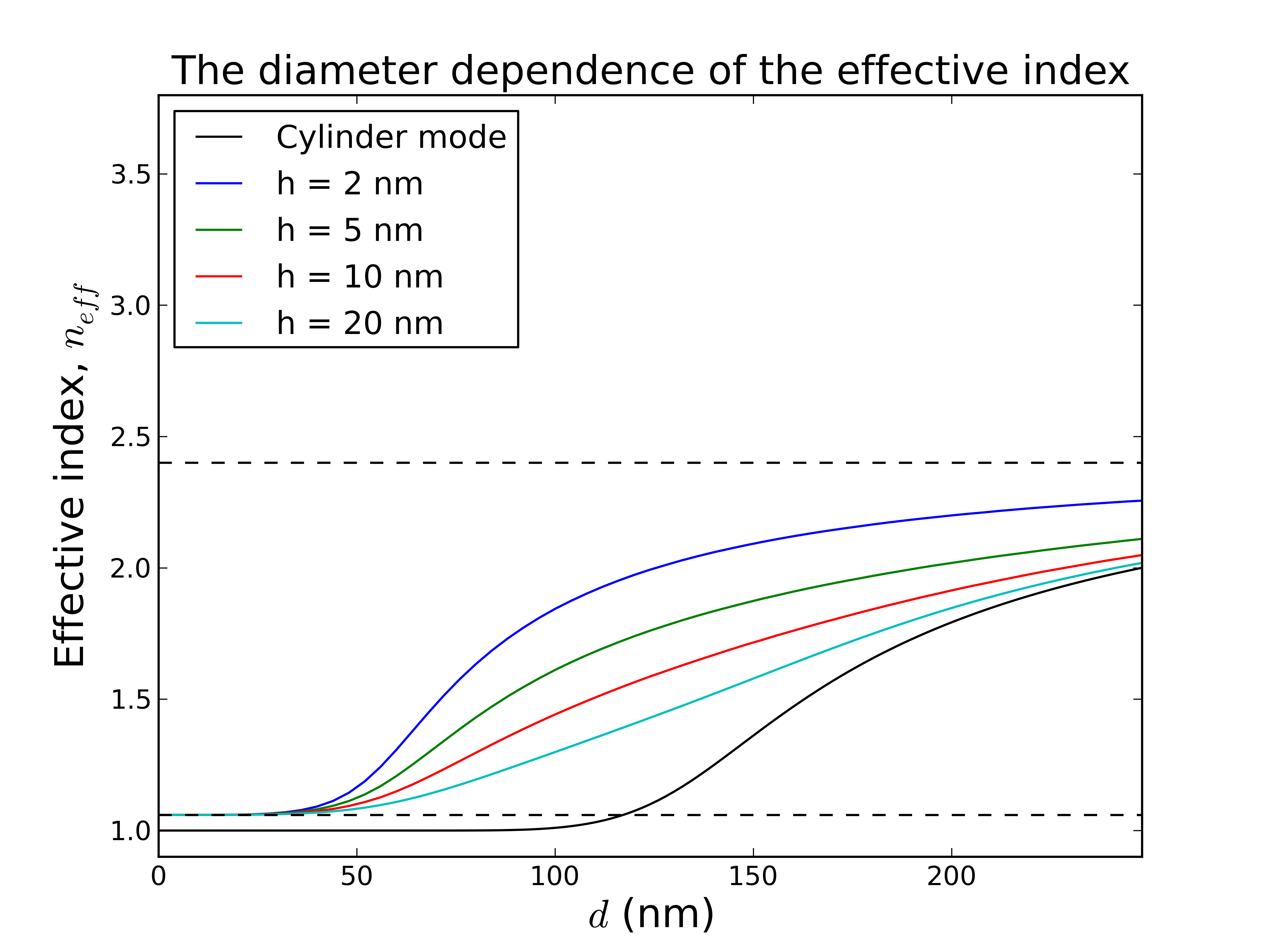
In accordance with general argumentation given in Section II we next present two sets of plots. Fig. 4 corresponds to the case of fiber with comparatively low refractive index, , the parameters of the waveguide are taken accordingly to experimental work Oulton2009 . Fig. 4 corresponds to opposite limit, when . Parameters of these two plots differ only for metal permittivity , the value is chosen for Fig. 4. Here, we do not concretize the material of the metal screen, our goal is just to demonstrate the qualitative difference of the guiding mode properties for the case (3).
Presented results indicate that when fiber diameter is decreased, the HPP-mode loses confinement along the metal and eventually (at ) becomes a surface plasmon-polariton mode of the flat metal-vacuum interface. Herewith the effective index of the HPP-mode monotonically decreases to that of this SPP-mode. Thus all dispersion curves have the same asymptotic at small . Two different behavior are possible at the opposite limit of large diameter. As the diameter , the HPP-mode can asymptotically tend either fundamental single fiber mode or the fundamental mode of the planar three-layer system, the choice depends on the gap width . If the gap thickness is below than (Eq.(1)) the HPP-mode approaches the CGD-mode with the diameter increasing. In the case the crossover between the asymptotics occurs at (black arrows at Fig. 4) which is determined as
| (7) |
For the HPP-mode becomes the cylinder-like in the limit of the large diameter. In the case the critical diameter corresponding to the transition between small-diameter and large-diameter asymptotics is defined by the equation , where is the diameter dependence of the effective index of the single fiber fundamental mode. If the condition is valid one can derive that the localization of this mode is exponentially small, , where
| (8) |
and is Euler-Mascheroni constant.
Let us suppose the effective index of the CGD-mode not to be significantly above that of bulk plane wave in the fiber medium, . For example, this assumption is true at the conventional plasmonic condition when the absolute value of metal permittivity is sufficiently greater than the dielectric permittivity, . Just the case is realised at Fig.3 and Fig.4. Then the field penetration depth into the upper dielectric is quite large as well as the HPP-to-CGD crossover diameter , so the CGD-mode does not provide the strong confinement. Therefore there are no advantages of CGD-like limit in the case from the view of HPP-mode confinement. For a given frequency and gap width the choice with the strongest coupling of the fiber mode and the surface plasmon polariton mode, corresponding to , provides the strongest localization of the field within nanogap due to the great contrast of permittivities XiangZhang_2008_NaturePhot . At the same time significant part of energy is transferred inside the fiber, thus the waveguide mode confinement is achieved largely due to the boundedness of the high-permittivity dielectric part of the waveguide. Once the diameter of the fiber is optimum and the gap width is small enough the advantages of the hybrid architecture are used completely: cross section size of the system can be much less than the wavelength and mode confinement is much stronger than for uncoupled single fiber or flat metal-dielectric interface. To achieve further increase of the HPP-mode confinement the fiber with higher dielectric constant should be used.
Next let us assume that effective index of the CGD-mode is significantly larger than the refractive index of the fiber medium. This can be achieved by diminishing the gap thickness in the case that corresponds to the Fig.4. Then the CGD-mode has strong confinement so the crossover diameter can be decreased to deep subwavelength scale, , by tuning the gap width. Therefore the attractive CGD-like asymptotic can be achieved by HPP-mode with very small diameter of cylinder providing the wished structure of the mode with the strong transversal localization in two dimensions within the gap region and exponential decaying into the cylinder. Note that in the case the top part of the fiber cross section is at distances much larger than from the gap and its particular shape does not play role any more.
IV Conclusion
In the paper we have proposed the novel approach for hybrid plasmonic waveguide design providing wide opportunities for HPP-mode property controlling. When the absolute permittivity of the metal is less than that of the dielectric the hybrid effective index is unlimitedly diverges (Eq.(4)) with gap width decreasing. High effective index provides strong confinement of the electromagnetic field in two dimensions within the nanometer-scale gap region. Thus the mode size can be simply controlled by tuning the waveguide’ geometry at fixed frequency and materials constituting the waveguide. The advantages of the case are confirmed by both qualitative analysis within planar three-layer model and rigorous semi-analytical method describing the HPP-mode propagation in general. The propagation distance of hybrid mode reduces with the mode size reduction. To achieve long-range propagation at fixed degree of localization one should minimize loss tangent of the metal. It should be noted that simultaneous satisfying of both conditions and at optical and near infrared frequencies is a challenging task. Thus implementation of the waveguide loss compensation techniques would be required to use such hybrid waveguide as a component of the miniaturized photonic circuits. Another potential application of our waveguide design lies in study field of the resonant plasmons. The resonance condition for a surface plasmon-polariton at a planar metal-dielectric interface is the fine-tuning of the permittivities, Avrut_2004 . Thus for particular metal the resonance can be achieved only in a narrow spectral range. While resonant increasing of the CGD-mode effective index requires only the geometrical condition . Thus for the conductor-gap-dielectric structure the resonance of plasmonic mode can be attained by gap width decreasing at any frequency as long as the condition is valid.
Appendix A Numerical method
The theoretical description of the hybrid waveguide is inhibited by its complex geometry. In general we should chose such system of coordinates where the surfaces of the waveguide are the isolines and Helmholtz equation can be solved by separation of variables. The hybrid geometry corresponds to the so called bipolar coordinates based on two sets of orthogonal circles. In this coordinate system the Helmholtz equation has quite complicated form and accordingly the set of eigen functions cannot be found analytically. However the unknown hybrid eigen functions can be expressed in terms of known solutions of the Helmholtz equation in other coordinate systems. It is convenient to represent the total electromagnetic field of HPP-mode as the superposition of the all modes of single fiber(cylindrical functions) and all SPP modes(evanescent plane waves) with some unknown coefficients of expansion.
We chose the Cartesian system of coordinates with origin at axis of the cylinder which is -axis (Fig. 6). Supposing the structure of the fundamental hybrid mode to be symmetric with respect to -axis we can describe the longitudinal component of the electric field as
| (9) |
and -components of the magnetic field as
| (10) |
where and .
To write the corresponding equations, it is convenient to express the field inside dielectric in terms of only plane evanescent waves, when we impose the continuity conditions on the boundary of the metal, and in terms of angular harmonics, for the cylindrical surface. We solve it by using the evanescent plane wave expansion of modified cylindrical functions and angular harmonic spectrum of the evanescent plane waves Mac
| (11) |
| (12) |
| (13) | |||
| (14) |
where
| (15) | |||
| (16) |
| (17) | |||||
| (18) |
Thus the electromagnetic fields in surrounding medium close to the dielectric waveguide can be written as
The corresponding expressions for the fields close to the surface of the metal are
It can be easily derived from the Maxwell’s equations that for the normal components
| (19) | |||||
| (20) |
where is tangent to the interface coordinate in the transversal plane.
The continuity conditions on the metal surface for , , and lead to the first system of linear homogeneous equations (SLE) on coefficients , , , , , . The corresponding continuity conditions for , , and on the cylindrical surface produce the second SLE on amplitudes , , , , , , which is now integral with respect to , . In order to avoid integration of the unknown functions we express the coefficients , in the terms of , from the first SLE and substitute them into the second SLE. The procedure leads to the infinite system of linear homogeneous algebraic equations for coefficients , , , . In order to solve the system numerically one should truncate it to a finite size. Then the propagation constant of the fundamental hybrid mode can be determined from the condition of vanishing of the characteristic determinant.
Acknowledgments
We thank I. R. Gabitov for valuable advices and V. V. Lebedev for fruitful discussions. The work was partially supported by the Russian Federation Government FRBR 12-02-01365-a, Council of the President of the Russian Federation grant No. -324.2012.5, the Russian FTP Kadry , and foundation Dynasty.
References
- (1) Born M., Wolf E., Principles of Optics (Cambridge Univ. Press, 1999.)
- (2) Gramotnev D. K. and Bozhevolnyi S. I. “Plasmonics beyond the diffraction limit,” Nat. Phot. 4, 83 91 (2010)
- (3) Oulton R. F., Sorger V. J., Genov D. A., Pile D. F. P. and Zhang X., “Hybrid plasmonic waveguide for subwavelength confinement and long-range propagation,” Nat. Phot. 2, 496 (2008)
- (4) Sorger V. J., Ziliang Y, Oulton R. F., Bartal Y. W. G., Yin X. and Zhang X., “Experimental demonstration of low-loss optical waveguiding at deep sub-wavelength scales,” Nat. Comm. 2, 331 (2011)
- (5) Avrutsky I., Soref R. and Buchwald W., “Sub-wavelength plasmonic modes in a conductor-gap-dielectric system with a nanoscale gap,” Opt. Express 18, 348 363 (2010)
- (6) Borghi R., Gori F., Santarsiero M., Frezza F. and Schettini G., “Plane-wave scattering by a perfectly conducting circular cylinder near a plane surface: cylindrical-wave approach,” J. Opt. Soc. Am. A. 13, (1996)
- (7) Borghi R., Santarsiero M., Frezza F. and Schettini G., “Plane-wave scattering by a dielectric circular cylinder parallel to a general reflecting flat surface,” J. Opt. Soc. Am. A. 14, (1997)
- (8) Takahara J., Yamagishi S., Taki H., Morimoto A. and Kobayashi T., “Guiding of a one-dimensional optical beam with nanometer diameter,” Opt. Lett. 82, 11581160 (1997)
- (9) I. Avrutsky, I. Salakhutdinov, J. Elser, and V. Podolskiy, “Highly confined optical modes in nanoscale metaldielectric multilayers, Phys. Rev. B 75, 241402 (2007)
- (10) Ishikawa A., Zhang S., Genov D. A., Bartal G. and Zhang X., “Deep Subwavelength Terahertz Waveguides Using Gap Magnetic Plasmon”, Phys. Rev. Let. 102, 043904 (2009)
- (11) Nam S. H., Taylor A. J. and Efimov A., “Subwavelength hybrid terahertz waveguides,” Opt. Express. 17, 22890 (2009)
- (12) West P. R., Ishii S., Naik G. V., Emani N. K., Shalaev V. M. and Boltasseva A., “Searching for better plasmonic materials,” Laser Photonics Rev. 4, (2010)
- (13) Marcuse D., Light Transmission Optics (New York: Van Nostrand Reinhold, 1972)
- (14) Bulushev A. G., Dianov E. M. and Okhotnikov O. G., “Propagation of the radiation in two identical coupled waveguides,” Sov. J. Quantum Electron. (1988)
- (15) Zakowicz W., “Two coupled dielectric cylindrical waveguides,” J. Opt. Soc. Am. A 14, (1997)
- (16) Oulton R. F., Sorger V. J., Zentgraf T., Ren-Min Ma, Gladden C., Dai L., Bartal G. and Zhang X., “Plasmon lasers at deep subwavelength scale,” Nat. 461, 629 (2009)
- (17) I. Avrutsky, “Surface plasmons at nanoscale relief gratings between a metal and a dielectric medium with optical gain,” Phys. Rev. B 70, 155416 (2004)
- (18) Borghi R., Frezza F., Santarsiero M. and Schettini G., “Angular spectrum of modified cylindrical wave-functions,” International Journal of Infrared and Millimeter Waves 20, (1999)