Ultracompact all-dielectric superdirective antennas
Abstract
We demonstrate a simple way to achieve superdirectivity of electrically small antennas based on a spherical dielectric particle with a notch. We predict this effect theoretically for nanoantennas excited by a point-like emitter located in the notch, and then confirm it experimentally at microwaves for a ceramic sphere excited by a small wire dipole. We explain the effect of superdirectivity by the resonant excitation of high-order multipole modes of electric and magnetic fields which are usually negligible for small perfect spherical particles.
Electrically small radiating systems whose directivity exceeds significantly that of a dipole are usually called superdirective Balanis (1982). Superdirectivity is an important property of radio-frequency antennas employed for space communications and radioastronomy, and it can be achieved in antenna arrays in a narrow frequency range and for a sophisticated system of phase shifters Balanis (1982). Achieving high radiation directivity is also important for actively studied optical nanoantennas Taminiau, Stefani, and Hulst (2008); He et al. (2009); Jain and El-Sayed (2010); Alu and Engheta (2010); Novotny and van Hulst (2011); Mahendra and Nelson (2011); Rodriguez et al. (2012); Biagioni, Huang, and Hecht (2012). Similar to radio-frequency antennas, a nanoantenna converts localized electromagnetic field to freely propagating light, and vice versa Novotny and van Hulst (2011); Biagioni, Huang, and Hecht (2012). For prospective optical wireless circuits on a chip, nanoantennas are required to be highly directive and compact Alu and Engheta (2010). In nanophotonics higher directivity can be achieved in arrayed plasmonic antennas utilizing the Yagi-Uda design Novotny and van Hulst (2011); Biagioni, Huang, and Hecht (2012); Taminiau, Stefani, and Hulst (2008). However, such nanoantennas have the size larger than the radiation wavelength , and individual elements of these arrays are not optically small. Usually, small plasmonic nanoantennas possess weak directivity close to that of a point dipole Jain and El-Sayed (2010); He et al. (2009); Rodriguez et al. (2012). Despite its importance, antenna’s superdirectivity in the optical frequency range was not discussed or demonstrated so far. Recently, it was suggested to use different dielectric and semiconductor materials for the development of antennas at the nanoscale Krasnok et al. (2011); Filonov et al. (2012); Krasnok et al. (2012). Such all-dielectric nanoantennas consist of high-permittivity nanoparticles having both resonant electric and magnetic optical responses Krasnok et al. (2011); Filonov et al. (2012); Krasnok et al. (2012); Evlyukhin et al. (2012); Kuznetsov et al. (2012). This approach allows to study an optical analogue of the so-called Huygens source, an elementary emitting system with properly balanced electric and magnetic dipoles oscillating with the same phase Balanis (1982); Krasnok et al. (2011); Filonov et al. (2012); Krasnok et al. (2012). As a result, nearly twice higher directivity than that of a single electric dipole has been reported. However, this directivity is still insufficient for nanophotonics applications. Several recent studies suggested to enhance directivity of nanoantennas by adjusting the distance between a point-like emitter and plasmonic nanoparticles Rolly et al. (2011) or employing a core-shell plasmonic resonator with metamaterials Alu and Engheta (2007).
In this Letter we reveal, for the first time to our knowledge, a novel way for achieving superdirectivity of antennas with a subwavelength (maximum size 0.4-0.5 ) radiating system comprising a point-like emitter and a dielectric particle with a small notch. This effect is achieved without using complex antenna arrays, and it is valid for a wide range of frequencies.
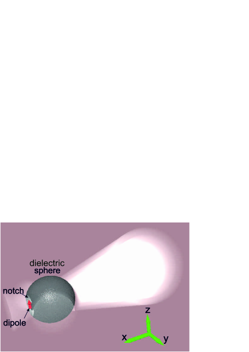
First, we demonstrate possibility to create a superdirective optically small nanoantenna that does not require metamaterial. We consider one semiconductor nanoparticle with the permittivity radiated by light at wavelength (for 440-460 nm this corresponds to a nanoparticle made of crystalline silicon Palik (1985)) and the radius nm being almost five times smaller than . For a perfect sphere, lower-order multipoles for both electric and magnetic fields are excited while the contribution of higher-order modes is negligible Krasnok et al. (2011); Filonov et al. (2012); Krasnok et al. (2012). However, making a small notch in the spherical particle breaks the symmetry allowing the excitation of higher-order multipole moments of the sphere. This is achieved by placing a nanoemitter (e.g. a quantum dot) within a small notch created on the sphere surface, as shown in Fig. 1. The notch in our example has the shape of a hemisphere with a radius . The emitter can be modeled as a point-like dipole and it is shown in the figure by a red arrow. It turns out that such a small modification of the sphere would allow the efficient excitation of higher-order spherical multipole modes.
It is important to mention that our approach is seemingly close to the idea of Refs. Boriskina et al. (2006); Wang et al. (2010) where a small notch on a surface of a semiconductor microlaser was used to achieve higher emission directivity by modifying the field distribution inside the resonator Scully (2010). An important difference between those earlier studies and our work is that the design discussed earlier is not optically small and the directive emission is not related to superdirectivity. In our case, the nanoparticle is much smaller than the wavelength, and our design allows superdirectivity.
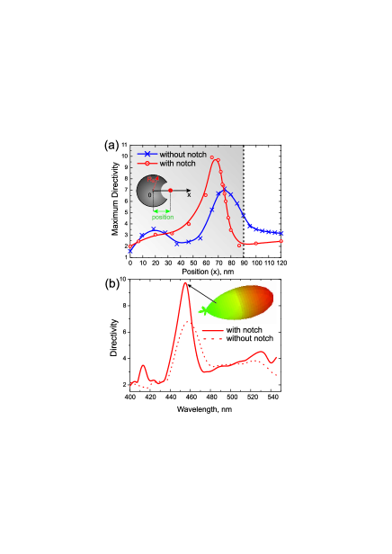
To study the problem numerically, we employ the software package CST Microwave Studio with the super-computing system Tesla S2050. Figure 2(a) shows the dependence of the maximum directivity on the position of the emitting dipole in the case of a sphere nm without a notch, at the wavelength nm (blue curve with crosses). This dependence has the maximum () when the emitter is placed inside the particle at the distance 20 nm from its surface. The analysis shows that in this case the electric field distribution inside a particle corresponds to the noticeable excitation of higher-order multipole modes. This becomes possible due to strong inhomogeneity of the external field produced by the nanoemitter. Furthermore, the excitation of higher-order multipoles can be significantly improved by making a small notch in the silicon spherical nanoparticle and placing the emitter inside that notch, as shown in Fig. 1. This modification of the nanoparticle transforms it into a resonator for high-order multipole moments.
In our problem, the notch has the form of a hemisphere with the center it the dielectric nanoparticle’s surface. The optimal radius of the notch is nm, that we find by means of numerical optimization. Red curve with circles in the Fig. 2(a) shows maximum of directivity corresponding to this geometry. Maximal directivity at wavelength 455 nm is . Figure 2(b) shows the dependence of directivity on the wavelength with and without a notch. The inset shows the three-dimensional radiation pattern of the structure at 455 nm. This pattern has an angular width (at the power of 3 dB) of the main lobe of .
Expansion of the field into multipoles offers an illustrative description of the internal field composition for the spherical particle. This is given by a series of spherical harmonics with the coefficients and , which characterize the electrical and magnetic multipole moments Jackson (1998),
| (1) | |||||
| (2) |
where
and are densities of the induced electrical charges and polarization currents that can be easily expressed through the internal field and the complex permittivity of the sphere, - spherical harmonics of the orders , and , is the speed of light. Coefficients and determine the electric and magnetic mutipole moments (namely, dipole at , quadrupole at , etc.). In the coordinate system shown in Fig. 1(a), we can write the electric and magnetic dipole moments ( and , respectively) in the form Jackson (1998),
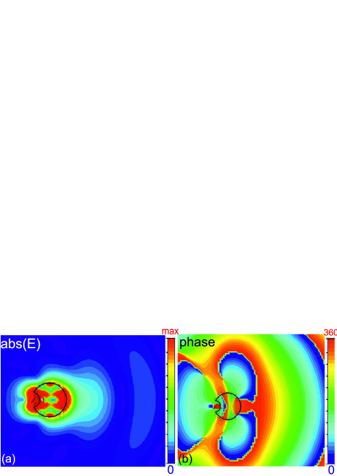
In general, the multipole coefficients determine not only the mode structure of the internal field but also the angular distribution of the radiation. Internal field was calculated numerically with the expansion into the multipole series. Figures 3(a,b) show the distribution of the absolute values and phases of the electric field. Electric (as well as magnetic) field intensity inside the particle is strongly inhomogeneous at 455 nm (i.e. in the regime of maximal directivity). In this regime, the internal area where the electric field oscillates with approximately the same phase is maximal. This area is located near the back side of the spherical particle, as can be seen in Fig. 3(b). In other words, in the regime of maximal directivity the nanoparticle acts as a device which straightens the surfaces with same phase of the emitter’s near field.
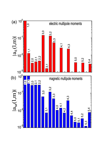
The values of high-order multipole moments for this electric field distribution are calculated with the use of Eqs. (1) and (2), and they are shown in Figs. 4(a,b), where we observe strong high-order multipoles excited together with the electric and magnetic dipoles , , , and . We notice that the absolute values of all magnetic moments are larger than those of the electric moments in the corresponding multipole orders. The spectrum of noticeably excited magnetic moments is also larger than that for the electric moments. Physically, this means that the presence of the notch has the greatest impact on the value of the polarization current , whereas the distribution of the induced charges is weakly affected by the notch.
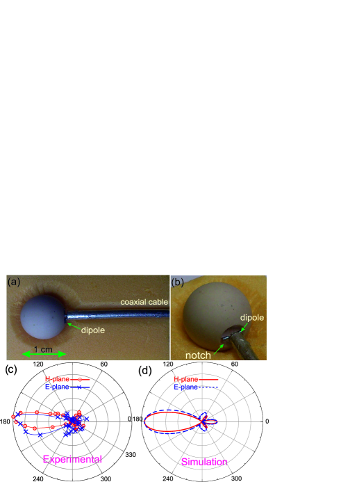
We have confirmed the generality of the predicted effect by studying the similar problem in the microwave range. To do this, we scale up the nanoantenna discussed above to the microwave frequencies. As a high-permittivity all-dielectric antenna in this frequency range, we employ MgO-TiO2 ceramic Filonov et al. (2012) characterized at microwaves by dielectric constant of 16 and dielectric loss factor of (1.12-1.17)10-4. We use the particle with the radius of mm and apply a small vibrator Balanis (1982) excited by a coaxial cable [see Figs. 5(a,b)]. The size of the hemispherical notch is approximately equal to mm. Styrofoam material with the dielectric permittivity close to 1 is used to fix the antenna in the azimuthal-rotation unit, as shown in Figs. 5(a,b). First, we perform numerical simulations of this antenna in CST Microwave Studio, and observe high directivity of this dielectric antenna at the frequency 16.8 GHz. Next, we study experimentally the radiation pattern of the antenna in the anechoic chamber. The results of the experimental measurements and numerical simulation of the radiation pattern in both - and -planes are summarized in Figs. 5(c),(d). Radiation patterns in both the planes are narrow beams with a lobe angle about 35∘. Experimental coefficients of the directivity in both - and -planes are equal to 5.9 and 8.4, respectively. The numerical values of these quantities are equal to 6.8 and 8.1. Our experimental data is in a very good agreement with the numerical results. The small difference between the experimental and numerical results in the E plane, can be explained by the asymmetry of the dipole.
Note, that the observed directivity is the same as one of all-dielectric Yagi-Uda antenna with size about 2 wavelength Filonov et al. (2012). However, the total size of our antenna with notch is . Thus, our experiment is clearly demonstrating superdirectivity performance.
In conclusion, we have proposed a novel and frequency-independent approach to achieve antenna’s superdirectivity through the excitation of electric and magnetic higher-order multipole modes in the electrically small dielectric particle with a noth. In the visible frequency range, we have studied this effect numerically for a subwavelength spherical c-Si nanoparticle with a notch on its surface. We have demonstrated that by locating a nanoemitter in the notch provides a strong excitation of higher-order modes and therefore high values of directivity not achievable for small spheres without a notch. Then, we have demonstrated experimentally that microwave antennas with a notch demonstrate the similar property of superdirectivity. Our results introduce an important concept of all-dielectric notched antennas, which is applicable to a wide frequency range and would allow creating a new generation of highly directed emitters with a variety of useful applications.
The authors thank P. V. Kapitanova for valuable discussions. This work was supported by the Ministry of Education and Science of the Russian Federation, Dynasty Foundation (Russia), and the Australian Research Council.
References
- Balanis (1982) C. Balanis, Antenna Theory: Analysis and Design (New York ; Wiley, 1982).
- Taminiau, Stefani, and Hulst (2008) T. H. Taminiau, F. D. Stefani, and N. F. Hulst, Optics Express 16, 10858 (2008).
- He et al. (2009) S. He, Y. Cui, Y. Ye, P. Zhang, and Y. Jin, Materials Today 12, 16 (2009).
- Jain and El-Sayed (2010) P. K. Jain and M. A. El-Sayed, Chemical Physics Letters 487, 153–164 (2010).
- Alu and Engheta (2010) A. Alu and N. Engheta, Phys. Rev. Lett. 104, 213902 (2010).
- Novotny and van Hulst (2011) L. Novotny and N. van Hulst, Nat. Photon. 5, 83 (2011).
- Mahendra and Nelson (2011) R. Mahendra and D. Nelson, Metal Nanoparticles in Microbiology (Springer, 2011).
- Rodriguez et al. (2012) S. R. K. Rodriguez, S. Murai, M. A. Verschuuren, and J. G. Rivas, Phys. Rev. Lett. 109, 166803 (2012).
- Biagioni, Huang, and Hecht (2012) P. Biagioni, J. Huang, and B. Hecht, Rep. Prog. Phys. 75, 024402 (2012).
- Krasnok et al. (2011) A. E. Krasnok, A. E. Miroshnichenko, P. A. Belov, and Y. S. Kivshar, JETP Lett. 94, 635 (2011).
- Filonov et al. (2012) D. S. Filonov, A. E. Krasnok, A. P. Slobozhanyuk, P. V. Kapitanova, E. A. Nenasheva, Y. S. Kivshar, and P. A. Belov, Appl. Phys. Lett. 100, 201113 (2012).
- Krasnok et al. (2012) A. E. Krasnok, A. E. Miroshnichenko, P. A. Belov, and Y. S. Kivshar, Optics Express 20, 20599 (2012).
- Evlyukhin et al. (2012) A. B. Evlyukhin, S. M. Novikov, U. Zywietz, R. L. Eriksen, C. Reinhardt, S. I. Bozhevolnyi, and B. N. Chichkov, Nano Lett. 12, 3749 (2012).
- Kuznetsov et al. (2012) A. I. Kuznetsov, A. E. Miroshnichenko, Y. H. Fu, J. Zhang, and B. Lukyanchuk, Sci. Rep. 2, 492 (2012).
- Rolly et al. (2011) B. Rolly, B. Stout, S. Bidault, and N. Bonod, Opt. Lett. 36, 3368 (2011).
- Alu and Engheta (2007) A. Alu and N. Engheta, IEEE Trans. on Antennas and Propagation 55, 3027 (2007).
- Palik (1985) E. Palik, Handbook of Optical Constant of Solids (San Diego, Academic, 1985).
- Boriskina et al. (2006) S. Boriskina, T. Benson, P. Sewell, and A. Nosich, IEEE J. Select. Topics Quantum Electron. 12, 1175 (2006).
- Wang et al. (2010) Q. J. Wang, C. Yan, N. Yu, J. Unterhinninghofen, J. Wiersig, C. Pflugl, L. Diehl, T. Edamura, M. Yamanishi, H. Kan, and F. Capasso, PNAS 107, 22407 (2010).
- Scully (2010) M. O. Scully, PNAS 107, 22367 (2010).
- Jackson (1998) J. Jackson, Classical Electrodynamics (New York : Wiley, 1998).