Studies on fast triggering and high precision tracking with Resistive Plate Chambers
Abstract
We report on studies of fast triggering and high-precision tracking using Resistive Plate Chambers (RPCs). Two beam tests were carried out with the 180 GeV muon beam at CERN using RPCs with gas gaps of 1.00 or 1.15 mm and equipped with readout strips with 1.27 mm pitch. This is the first beam test of RPCs with fine-pitch readout strips that explores simultaneously precision tracking and triggering capabilities. RPC signals were acquired with precision timing and charge integrating readout electronics at both ends of the strips. The time resolution was measured to be better than 600 ps and the average spatial resolution was found to be 220 m using charge information and 287 m using timing information. The dual-ended readout allows the determination of the average and the difference of the signal arrival times. The average time was found to be independent of the incident particle position along the strip and is useful for triggering purposes. The time difference yielded a determination of the hit position with a precision of 7.5 mm along the strip. These results demonstrate the feasibility using RPCs for fast and high-resolution triggering and tracking.
keywords:
RPC , trigger , tracking , time resolution , spatial resolutionPACS:
12.38.Qk , 12.15.Mm1 Introduction
Resistive Plate Chambers (RPCs) [1] have been rapidly adopted in large-scale particle physics experiments due to their excellent timing capabilities, reliability, low cost, and ability to easily scale to large areas. In major collider and neutrino experiments, RPCs are mainly used as trigger or time-of-flight devices with a typical time resolution of (ns) [2, 3, 4, 5, 6, 7, 8]. They are typically read out with centimeter-wide strips and have spatial resolutions of (cm) [9, 10]. However, studies have shown that RPCs with narrow readout strips can provide sub-millimeter spatial resolution using classic charge interpolation [11, 12] or other techniques [13]. Such high resolution and fast RPCs could be useful as trigger and precision tracking detectors in experiments at future lepton and hadron colliders.
To explore the feasibility of using RPCs for high-precision tracking and fast trigger devices, two beam tests were carried out with the 180 GeV muon beam at CERN. Single gas-gap RPCs equipped with fine-pitch strips were used. Both ends of the strips were read out using charge Analog-to-Digital Converters (ADCs) and fast Time-to-Digital Converters (TDCs). A detailed description of the RPCs used in these beam tests and their operations is described in Sec. 2. The spatial resolution of muon hits in the direction perpendicular to the readout strips (referred to as the “primary coordinate”), was measured in the 2011 beam test and the results are reported in Sec. 3. The results from the second beam test, focusing on measurements of RPC time resolution, spatial resolution of muon hits in the direction along the readout strips (referred to as the “second coordinate”), and mean signal arrival time from both ends of readout strips, are presented in Sec. 4. Conclusions are drawn in Sec. 5.
2 RPC chamber description
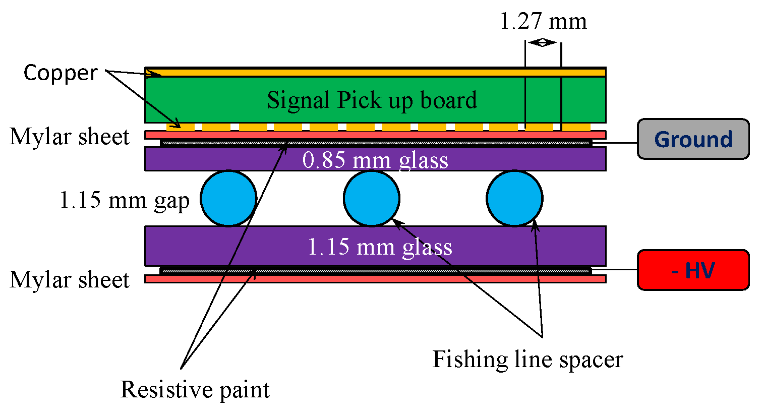
Single gas-gap RPCs with glass or Bakelite electrodes were used in these tests. The glass chambers were 96 32 cm2 and are depicted in Fig. 1. Two glass plates were separated by 1.15 mm using nylon monofilament placed along the longest dimension. The ground-side glass plate was 0.85 mm thick and the side with the high voltage applied was 1.15 mm thick. The outer surfaces of the glass plates were painted with resistive paint having a surface resistivity of 1-5 /. The size of the Bakelite RPC was 20 20 cm2, with a structure similar to the glass chambers but with a 1 mm gas gap and 2 mm thick electrodes.
Signal pickup boards with readout strips of 1.27 mm in pitch were placed on the ground sides of the chambers, and signals were read out via capacitive coupling. Negative high voltages were applied on the opposite-side plates. A three-component gas blend of Freon(94.7%):iC4H10(5%):SF6(0.3%) was used. The typical operational voltages for glass and Bakelite chambers were kV and kV respectively. The dark currents were measured to be less than 0.1 nA/cm2 for the glass chambers and 0.6 nA/cm2 for the Bakelite one.
3 Primary coordinate measurements
3.1 Experimental setup and readout electronics
The spatial resolution for the primary coordinate of the RPCs was measured using 180 GeV muons from the SPS-H8 beam line at CERN in October 2011. The schematic view of the experimental setup is shown in Fig. 2. The glass RPC, accompanied with two closely-spaced round scintillators, each 2 cm in diameter, was placed upstream in the beam line. These two scintillators, smaller than the readout area, were mainly used to measure the RPC efficiency. Two Bakelite RPCs and a small-diameter monitored drift tube (sMDT) chamber were installed at the downstream side. The sMDT chamber [14] was made of eight layers of 15 mm diameter drift tubes and was filled with an Ar(93%):CO2(7%) gas mixture at 3 bar absolute pressure. The average spatial resolution of individual drift tubes has been measured to be 120 m. The sMDT chamber can measure the direction of muon tracks with an angular resolution of 0.4 mrad [15] and thus provided precise measurements of the incident muon tracks. Two additional large-area scintillators were employed to give common trigger signals to all chambers.
In total, 72 strips from the glass RPC, terminated with 50 resistors, were read out from both ends in three groups of 24 channels. Each group was connected to a low-noise ATLAS custom MDT “mezzanine” card containing three 8-channel Amplifier-Shaper-Discriminator (ASD) chips [16] and a 24-channel TDC [17] chip which stored the arrival times of signal leading and trailing edges in a large memory buffer. The pulse height of the signal was measured by an ADC in the ASD chip and was encoded as the time over threshold between leading and trailing edges of the signal. The TDC has a least count of 0.78 ns. The data from three mezzanine cards were formatted, stored in a large derandomizing buffer and sent optically to the computer via a local processor. The same system was used to read out the data from the sMDT chamber using a common DAQ system.

3.2 Cluster size and efficiency
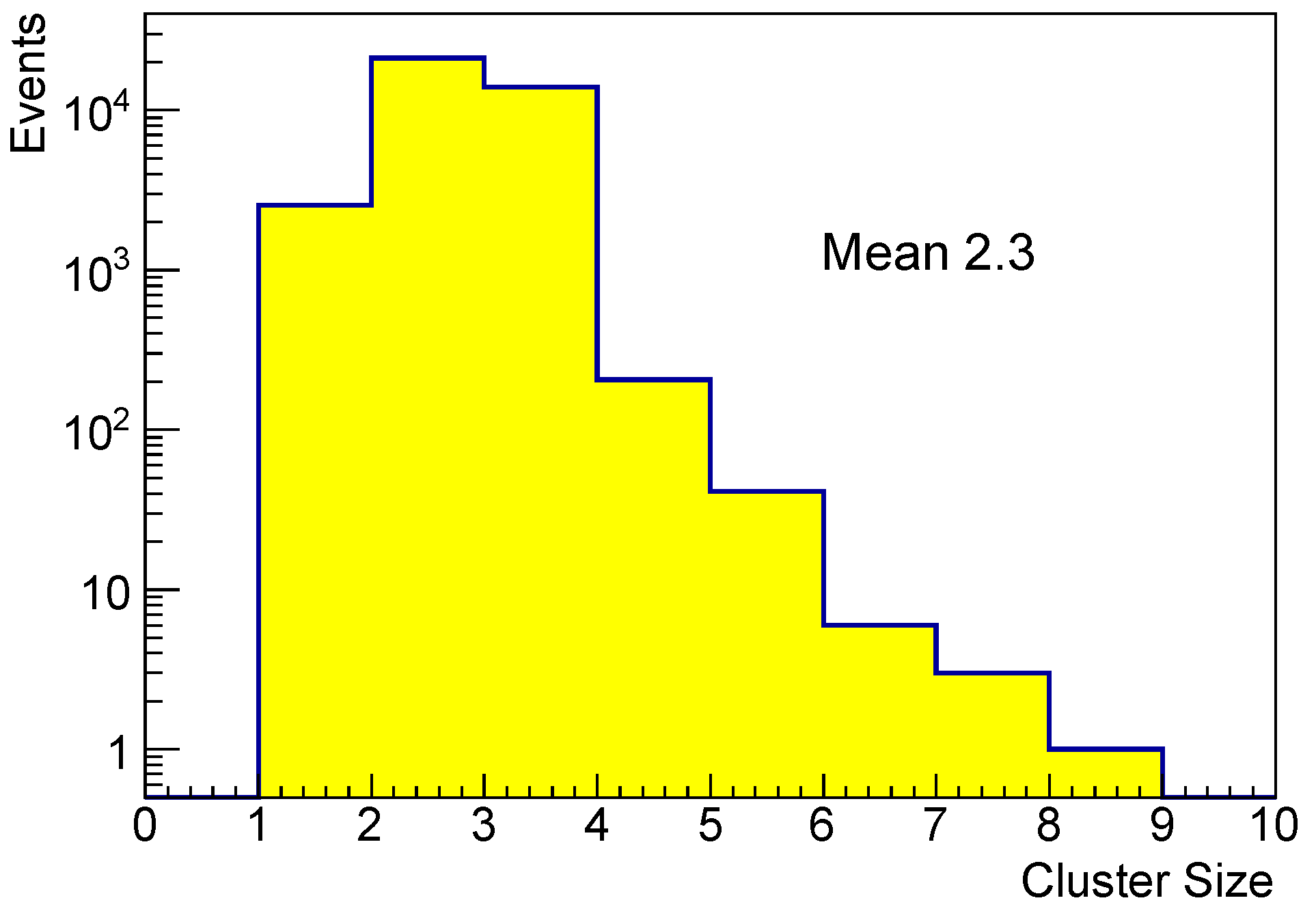
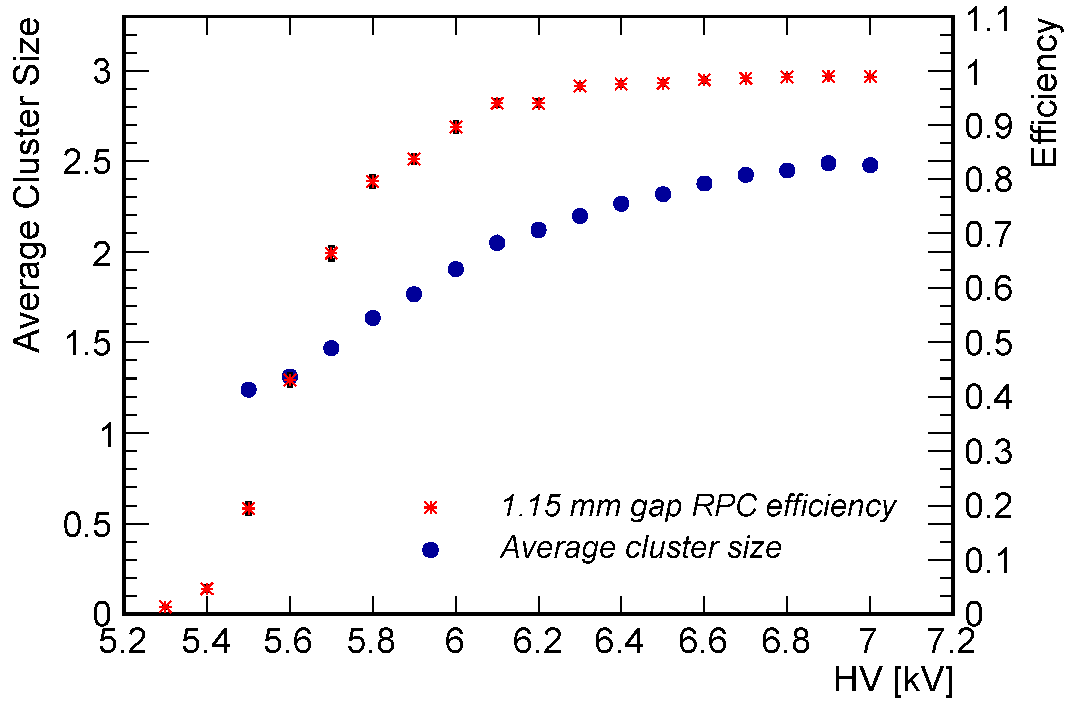
For events recorded by the glass RPC, the strip with the earliest arrival time was selected, and a 20 ns time window was opened after this earliest arrival time to look for hits on strips associated with the muon tracks. A cluster is defined as a group of adjacent strips or combinations of multiple strips separated by one missing strip. The distribution of the cluster size with a high voltage of 6.5 kV is shown in Fig. 3. The average cluster size was found to be 2.3 strips. Dependence of the average cluster size on the applied high voltage is shown in Fig. 4. The cluster size increases from 1.2 at 5.5 kV to 2.5 at 7.0 kV.
The glass chamber efficiencies at different high voltages were measured with a threshold of 5 fC on the total charge collected by each strip, and the efficiency curve is also shown in Fig. 4.
3.3 Spatial resolution
The glass RPC chamber was used for the primary coordinate measurements. Reference tracks from the sMDT chamber were extrapolated to the RPC. The spatial resolution is then defined as the difference between the measured position on the RPC and the expected position from the reference track provided by the sMDT.
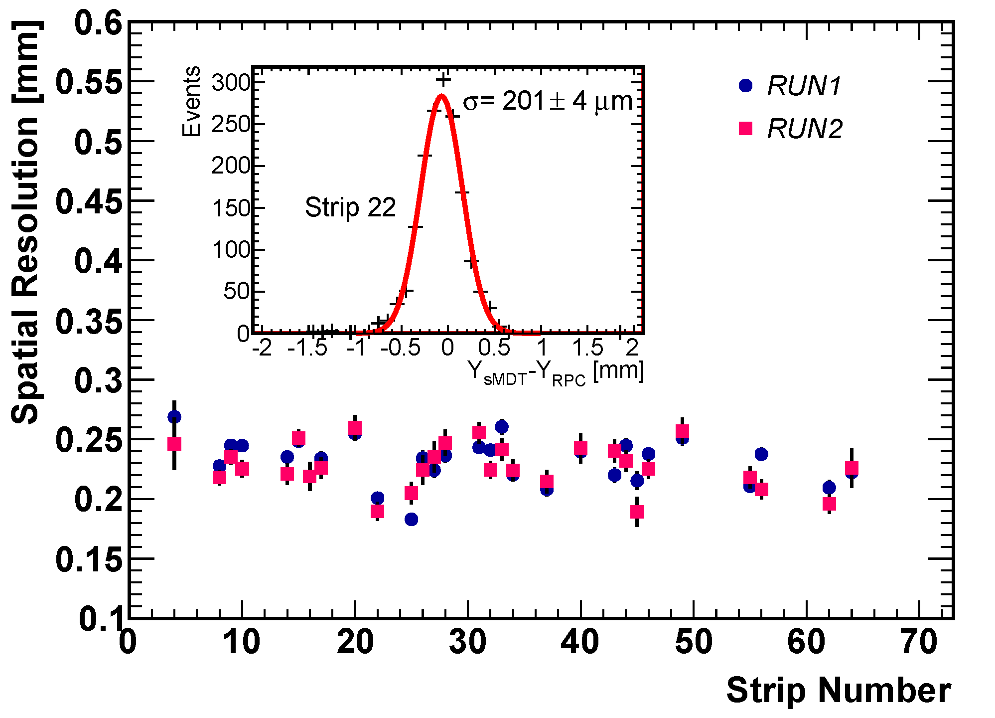
The track hit positions in the RPC were reconstructed with two different methods. For the first approach, the hit positions were determined as the weighted average of the strip center positions using strip charge ADCs as weights. Since a dedicated sMDT calibration was not available during the beam test and the RPC was placed almost half a meter away from the sMDT center, a conservative assumption of 100 m uncertainty for the predicted track hit positions was made. The RPC spatial resolutions after subtracting this uncertainty, are shown in Fig. 5 as a function of the hit position in the readout area for two separate runs with same running conditions. Some strips were missing due to the geometric cuts of the sMDT reference tracks. The residual distribution for a typical strip is also shown as an enclosed plot in Fig. 5. The average spatial resolution for all strips was found to be 220 m. However, it should be noted that the resolution obtained here is not the ultimate resolution that can be achieved with this detector. The ADC value measured with the ATLAS MDT electronics used in this beam test has a logarithmic dependence on the total charge deposited. Hence, the spatial resolution of the centroid calculated using these ADC values is worse than the one that would be reconstructed using the actual accumulated charge. Moreover, the RPC signals begin to saturate the MDT readout electronics and thus degrade the calculated hit position precision.
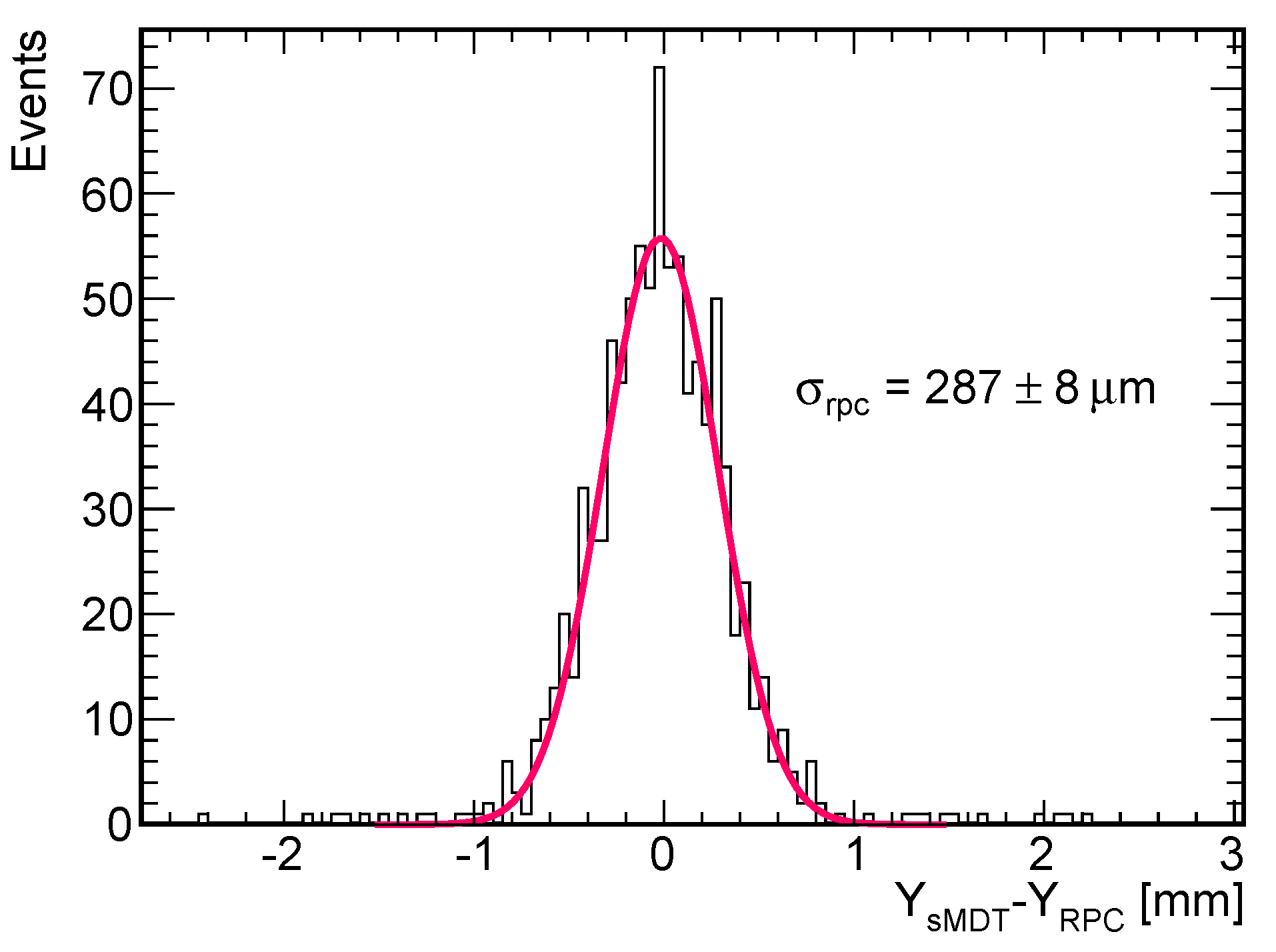
For the second approach, only the strip timing information was used. The fired strips were selected within the 20 ns time window after the earliest arrival time. The hit position was then calculated as the mean value of the central positions of all selected strips. The typical distribution of residuals between the predicted positions from sMDT and the calculated position on the RPC is shown in Fig 6. The spatial resolution was determined to be 287 m after the subtraction of 100 m estimated uncertainty on the predicted position from the sMDT. The ability to measure muon hit position with a precision of m within ns with a read out of only a few strips makes these RPC detectors excellent high-precision trigger devices for muon detection.
4 Time resolution and second coordinate measurements
4.1 Experimental setup and readout electronics
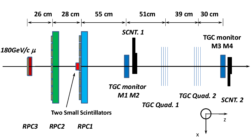
The narrow gas-gap RPC time resolution and second coordinate measurement capability were investigated in the same CERN beam line in June 2012 with a different experimental setup and readout electronics. The experimental setup using two glass chambers (denoted as RPC1 and RPC2) and a Bakelite chamber (denoted as RPC3) is illustrated in Fig. 7. The strips for the two glass chambers were placed perpendicularly to the strips of the Bakelite chamber. This layout enabled use of the Bakelite chamber to provide reference track hit positions for the glass chambers along their strip direction. Thin Gap Chamber (TGC) [18] doublets (2 layers) and quadruplets (4 layers) were placed at the downstream side of the beam line. Two big scintillators, 1.2 m apart, provided the global trigger for the RPC and TGC DAQ systems.
All three RPCs were read out using the electronics chain composed of NINO [19] front-end cards developed for the ALICE multi-gap RPC time-of-flight detector and TDC modules with a time resolution of 100 ps. Each NINO card, containing three eight-channel NINO chips for amplification, shaping and discriminating, accepts differential signals from the chamber. The strips of the two glass chambers were terminated to the ground through 1 M resistors, and both ends were capacitively coupled to the NINO inputs through 1 nF capacitors. For the Bakelite chamber, the strips were read out only from one end, also through 1 M decoupling resistors. Since ground sides of the chambers were equipped with signal pickup boards and negative high voltage were applied, only signals with negative polarities were sent to the NINO cards. All positive inputs to the NINO were AC coupled to the common ground of the chamber.
4.2 Time resolution
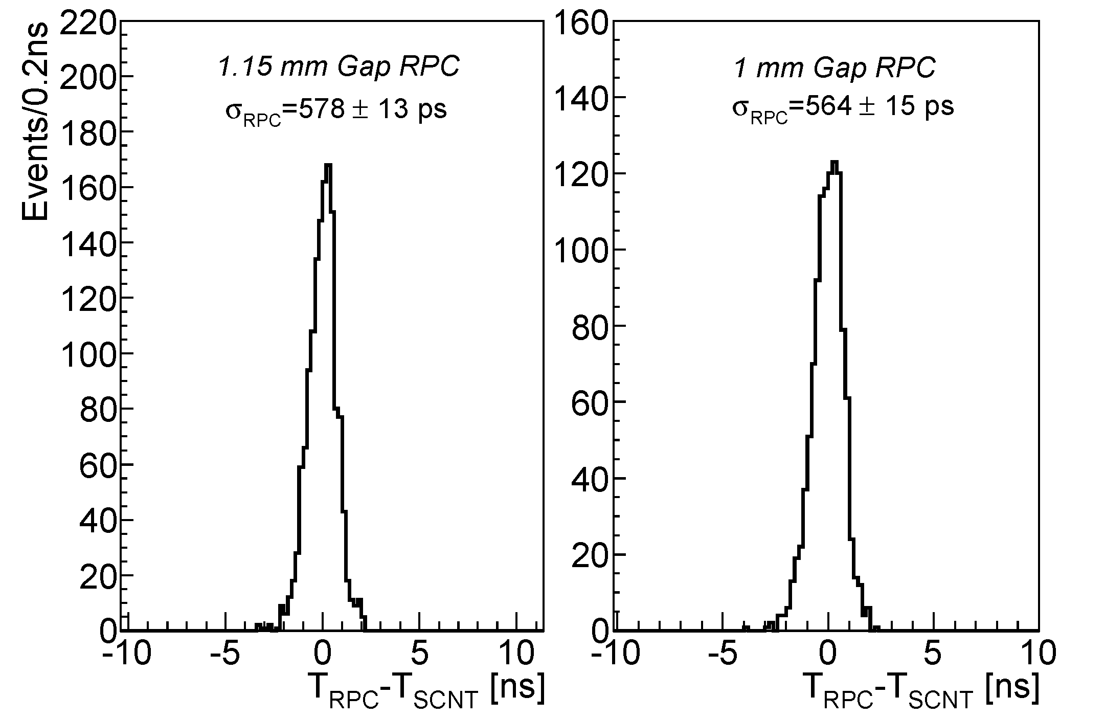
Time resolutions for 1.15 mm gas-gap glass chambers and 1 mm gas-gap Bakelite chamber were measured using the average time of the two small scintillators as the reference time. Since the time jitter for a single scintillator was measured to be 584 6 ps, the meantime of the two scintillators has an uncertainty of 413 4 ps for the overall measured time jitter. Time resolutions of 578 13 ps for the 1.15 mm gas-gap glass chamber and 564 15 ps for the 1 mm gas-gap Bakelite chamber were derived after removing the contribution from the reference time provided by the two scintillators. Distributions of the scintillator-corrected RPC time resolution are shown in Fig. 8. The charge information was used later to perform time-walk corrections. Such corrections yield a time resolution of 510 10 ps for 1.15 mm gas-gap glass chamber and 453 12 ps for the 1 mm gas-gap Bakelite chamber.
4.3 Meantime measurement
The mean value (meantime) of the signal arrival times from both ends of each readout strip was measured for the glass chambers at different positions along the strips. An exact location of the hit position along the glass chamber strip was measured independently using the Bakelite chamber.
The meantime as a function of the hit position is shown in Fig. 9 and shows no clear dependence between the meantime and the hit position. The mean value of the meantime distribution varies from strip to strip as expected due to different delays from the readout cables and circuits. After compensating for these delays and offsets channel-by-channel through a programmable logic circuit, it is possible to latch the coincidence window between multiple RPC layers within a few nanoseconds. With these timing corrections the trigger coincidence window can be minimized to reduce background in a high-rate environment.

4.4 Time difference and second coordinate measurements
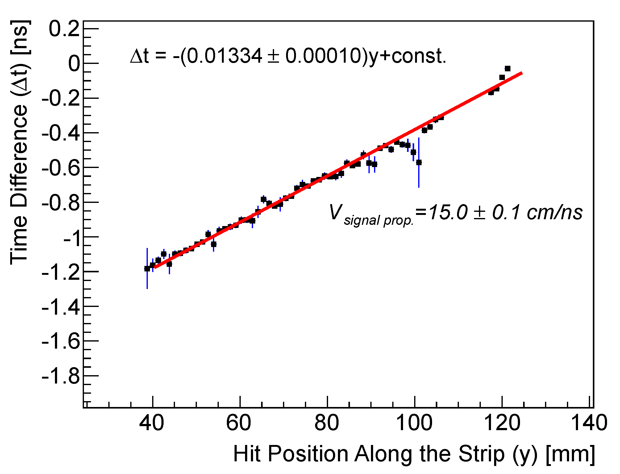
Time differences (t) from the two ends of the readout strips were measured, and the dependence on the muon hit position along the strip () is shown in Fig. 10. A linear fit of this dependence yields an estimation of the signal propagation speed of 15.0 cm/ns along the strip. Slight differences of the measured transmission speed, within 1.5 cm/ns, were observed for different channels. The resolution of the time difference distribution for a typical strip was measured to be 150 ps which was close to the 100 ps time resolution of the TDC module used.
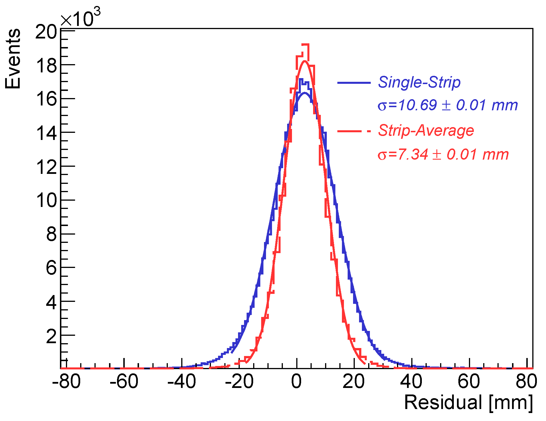
The spatial resolution along the strip direction in the glass RPC was measured by comparing the reconstructed positions in the glass RPC with the positions measured using the Bakelite RPC. Since the Bakelite chamber was also equipped with 1.27 mm-pitch readout strips, the predicted muon hit positions have sub-mm precision. For the glass RPC, the hit position was calculated as the product of the time difference from both ends and the signal propagation velocity divided by two. Two approaches were used for the determination of the muon hit position. One method only used the time difference information from a single strip. Another approach determined the hit position by averaging the values from multiple strips within the cluster. The residuals between the predicted and the reconstructed positions are shown in Fig. 11 for both approaches. Resolutions along the strip direction are found to be 10.69 mm using a single strip and 7.34 mm using multiple strips.
5 Conclusions
We have presented new developments of fast and high-precision trigger and tracking using RPCs. Two beam tests were performed with 1.0 mm gap Bakelite electrode and 1.15 mm gap glass electrode RPCs equipped with 1.27 mm fine-pitch strips and read out from both ends of the strips using charge ADCs and fast TDCs. The RPC time resolution was measured to be better than 600 ps. Spatial resolutions for the primary coordinate were experimentally measured to be better than 200 m using charge information and 287 m using hit arrival time information. Signal arrival time differences from both ends of the readout strips were used for the determination of second coordinates of incident muons, and resolutions better than 7.5 mm was achieved using TDCs with a time resolution of 100 ps.
The fine segmentation in the two-dimensional space, along with the excellent timing capability and uniform meantime for the signal from both ends make narrow-gap, fine-pitch RPCs an attractive high-precision trigger device for future lepton and hadron colliders.
6 Acknowledgments
We would like to thank M. Lippert and P. Schwegler from the Max Plank Institute, and G. Mikenberg, M. Shoa and their colleagues from the ATLAS TGC group for their help during the beam tests. The authors would also like to acknowledge M.C.S. Williams and R. Zouevski for their help using NINO front-end electronics. This work is supported in part by the Department of Energy under contracts DE-SC0007859 and DE-AC02-98CH10886, and by National Science Foundation of China under contract 11025528.
References
- [1] R. Santonico and R. Cardarelli, Nucl. Instr. and Meth. A 187 (1981) 377.
- [2] G. Aielli et al., Nucl. Instr. and Meth. A 533 (2004) 193.
- [3] M. Abbrescia et al., Nucl. Instr. and Meth. A 508 (2003) 137.
- [4] R. Arnaldi et al., Nucl. Instr. and Meth. A 451 (2000) 462.
- [5] M.C.S. Williams, Nucl. Instr. and Meth. A 478 (2002) 183.
- [6] A. Bertolin et al., Nucl. Instr. and Meth. A 602 (2009) 631.
- [7] G. Aielli et al., Nucl. Instr. and Meth. A 562 (2006) 92.
- [8] Q. Zhang et al., Nucl. Instr. and Meth. A 583 (2007) 278.
- [9] G. Cattani, Nucl. Instr. and Meth. A 661 (2012) S6.
- [10] R. Arnaldi et al., Nucl. Instr. and Meth. A 490 (2002) 51.
- [11] Q. Li et al., Nucl. Instr. and Meth. A 663 (2012) 22.
- [12] P. Fonte, Proceedings of XI Workshop on Resistive Plate Chambers and Related Detectors (2012). (to be published)
- [13] R. Cardarelli et al., Nuclear Physics B (Proc. Suppl.) 158 (2006) 25.
- [14] B. Bittner et al., Nucl. Instr. and Meth. A 628 (2011) 154.
- [15] Y. Benhammou et al., IEEE Nuclear Science Symposium Conference Record, Page 1761-1766, NP5. S-200.
- [16] J. Huth et al., Proceedings of the Fifth Workshop on Electronics for LHC Experiments (1999).
- [17] Y. Arai et al., IEEE Trans. Nucl. Sci. 49 (2002) 1164.
- [18] ATLAS Collaboration, JINST 3, S08003 (2008).
- [19] F. Anghinolfi et al., IEEE Trans. Nucl. Sci. 51 (2004) 1974.